
Summary of Contents for Technogym UNITY MINI
- Page 1 UNITY MINI MANUAL FOR INSTALLING UNITY MINI ON LEG PRESS MEDICAL EQUIPMENT UNITY MINI_INSTALLATION MANUAL REV 1.0 2016.11.28 1/43...
-
Page 2: Table Of Contents
1.3.1 PERSONAL PROTECTIVE EQUIPMENT ....................7 2 LEG PRESS MED EQUIPMENT UPGRADE KIT CODE ..................8 3 NECESSARY TOOLS ............................9 4 UNITY MINI INSTALLATION .......................... 10 4.1 REAR GUARD REMOVAL ........................10 4.2 CABLE PASSAGE THROUGH THE EQUIPMENT FRAME ................. 13 4.3 PREPARING THE WEIGHT STACK AND ADDITIONAL WEIGHT SENSOR .......... - Page 3 Blank page UNITY MINI_INSTALLATION MANUAL REV 1.0 2016.11.28 3/43...
- Page 4 The information in this manual is intended for QUALIFIED TECHNICAL PERSONNEL, who have been specifically trained by TECHNOGYM S.p.A. and are qualified to carry out fine tuning and start-up of the equipment, as well as major maintenance work and repairs, requiring in-depth understanding of the equipment, how it works, its safety devices and maintenance procedures.
- Page 5 Blank page UNITY MINI_INSTALLATION MANUAL REV 1.0 2016.11.28 5/43...
-
Page 6: General Warnings
1 GENERAL WARNINGS 1.1 INTRODUCTION This document is reserved for Technogym Service technicians, and is intended to provide authorized personnel with the necessary information to correctly carry out repairs and maintenance. A thorough understanding of the technical data contained herein is absolutely fundamental in order for the operator to achieve the highest level in professional training. -
Page 7: Useful Advise
1.2 USEFUL ADVISE Technogym advises you to plan your technical assistance task in the following way: Carefully assess the impressions reported by the Customer regarding the equipment’s operating faults and ask questions suitable to clarify the signs of the defect. -
Page 8: Leg Press Med Equipment Upgrade Kit Code
2 LEG PRESS MED EQUIPMENT UPGRADE KIT CODE EQUIPMENT UPGRADE KIT ENCODER 1 ENCODER 2 ADDITIONAL EQUIPMENT CODE CODE WEIGHT WIRE Leg press Med CL94 EICCL09 Table 1 UNITY MINI_INSTALLATION MANUAL REV 1.0 2016.11.28 8/43... -
Page 9: Necessary Tools
3 NECESSARY TOOLS 13mm articulation extension socket; Allen wrench with an 8mm insert; 17 mm fork wrench; Flat screwdriver; Ratchet with 13mm socket wrench; Ratchet with 4mm hexagonal key; 5mm hexagonal T wrench; Electrical tape; Fairlead spring; Cloth; Degreaser; Cutter; Ratchet with 13mm socket wrench;... -
Page 10: Unity Mini Installation
4 UNITY MINI INSTALLATION 4.1 REAR GUARD REMOVAL Remove the two self locked nuts located in the central part of the right and left rear guard. TOOL: 13mm articulation extension socket. Remove the two pulleys to permit the removal of the side cover and then the rear guard. - Page 11 Remove the right and left side covers. TOOL: flat screwdriver. Loosen the nuts fastening and right and left side guards. TOOL: ratchet with 13mm socket wrench. UNITY MINI_INSTALLATION MANUAL REV 1.0 2016.11.28 11/43...
- Page 12 Remove the two external screws on the right and left side guards. TOOL: ratchet with 4mm hexagonal key. Remove the four right and left upper and lower outer screws from the rear guard. TOOL: 5mm hexagonal T wrench. Remove the rear guard. UNITY MINI_INSTALLATION MANUAL REV 1.0 2016.11.28...
-
Page 13: Cable Passage Through The Equipment Frame
4.2 CABLE PASSAGE THROUGH THE EQUIPMENT FRAME Remove the plastic caps from: ZONE A: display zone; where the display unit bracket is fixed; ZONE B: power supply input zone (3 caps to be removed); ZONE C: weight stack zone; using a flat screwdriver. When the plastic caps are removed for cable passage, it is recommended to always use a piece of packaging plastic to protect the equipment frame from damage. - Page 14 The cable supplied in the kit consists of the following connectors that must pass through the equipment frame, as follows: CONNECTOR 1 - “male” connector towards the weight stack sensor bar: pass CONNECTOR 1 through the hole of the display zone and make it exit from the weight stack sensor zone. (follow the cable passage procedure indicated below).
- Page 15 When passing the cable through the equipment frame, use electrical tape to protect the parts not protected by the outer cable mesh. Proceed as follows to make CONNECTOR 1 exit from the weight stack sensor zone: Connect CONNECTOR 1 and CONNECTOR 2 to the fairlead spring, using electrical tape. Pass the fairlead spring from the hole located in ZONE A (display zone) to the hole located in ZONE B (power supply input zone) and make the cable exit.
- Page 16 Insert CONNECTOR 2 directed towards the power supply in the plastic support of the power supply connector. Insert the nut. The washer supplied in the kit must not be installed. Do not yet fasten the plastic support of the power supply connector to the equipment frame.
-
Page 17: Preparing The Weight Stack And Additional Weight Sensor
4.3 PREPARING THE WEIGHT STACK AND ADDITIONAL WEIGHT SENSOR Carefully clean the weight stack (reference rh plate guide bar), using a cloth on which a degreaser has been sprayed. Stick the white reflecting strip so it is aligned with the right plate guide bar of the weight stack. - Page 18 Objective: position the white reflecting strip in the portion of the additional weight that covers the additional weight sensor. For details, follow the procedure indicated below. Remove the additional weight from the guide of the additional weight and turn it 180°. Clean the additional weight carefully (reference right side) using a cloth on which a...
- Page 19 Remove the nuts and shims of the bolts that fasten the 2 guides of the additional weight (reference lower part of the rear guard). Remove the nuts and shims of the bolts that fasten additional weight support plate. Remove the nut and the shim of the bolt (reference upper part of the rear guard) that fastens the guide of the additional weight...
- Page 20 Connect the additional weight board (C) to the additional weight sensor cable (CABLE C). Position the additional weight board in Case 1 correspondence of the additional weight support plate. The three possible configurations of the additional weight support plate are shown to the side as well as the correct position of the CORRECT POSITION additional weight board in SELECTION...
- Page 21 Case 3 CORRECT POSITION Fit the additional weight board (C) to the additional weight support plate using two cross-head screws. Fasten the screws using pointed pliers and a Phillips screwdriver. Position the nuts (normal and self- locking) on the back of the plate. Fasten the additional weight sensor cable (CABLE C) and the weight stack sensor cable (CABLE D) on the back of the...
- Page 22 Position the weight stack sensor bar in the bottom of the guide of the additional weight. The distance from the bottom between the end of the guide of the additional weight and the weight stack sensor bar must be 4 cm – 1.57’’. Fasten the weight stack sensor bar to the guide of the additional weight.
- Page 23 Fasten the 2 guides of the additional weight and the additional weight support plate to the rear guard, as done originally. TOOL: 13mm socket wrench. The nuts of the guide of the additional weight are self-locking. The nuts of the additional weight support plate are normal.
- Page 24 Connect the additional weight sensor cable (CABLE C) and the weight stack sensor cable (CABLE D) to the weight stack sensor bar. Connection of the cables to the weight stack sensor bar: the connection shown in red should be avoided, as the contacts present in the sensor bar are very small and can be easily bent/damaged.
-
Page 25: Assembling The Encoder Unit
4.4 ASSEMBLING THE ENCODER UNIT Go to the carriage side front frame to install the encoder unit. Remove the guard (A) by unscrewing the 4 fastening screws. Remove the front cover metal sheet. UNITY MINI_INSTALLATION MANUAL REV 1.0 2016.11.28 25/43... - Page 26 1. Fit the encoder unit (plate + encoder + sprocket + cord around the pulley) on the bracket, using a hexagonal key, to fasten the 4 screws. 2. Fit the bracket (B) to the equipment frame, using the 2 bolts (F). 3.
- Page 27 Pull the encoder wire (E) and hook it to the pin. UNITY MINI_INSTALLATION MANUAL REV 1.0 2016.11.28 27/43...
- Page 28 Refit the guard metal sheet (A). UNITY MINI_INSTALLATION MANUAL REV 1.0 2016.11.28 28/43...
-
Page 29: Assembling The Display Unit
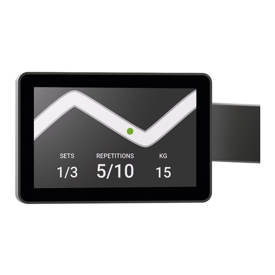
4.5 ASSEMBLING THE DISPLAY UNIT The following figure shows the correct position of the UNITY MINI display. The display unit assembly is explained in detail in the procedure provided below. Figure 1 UNITY MINI_INSTALLATION MANUAL REV 1.0 2016.11.28 29/43... - Page 30 Measure 5.5cm – 2.16’’ from the centre of the exit hole for the display (ZONE A) and attach a piece of electrical tape in correspondence of this distance; this will be the reference point for correctly positioning the display unit. Attach a shimming adhesive in correspondence of the curve of the bracket hook to the equipment...
- Page 31 Pass the cables with the connectors directed towards the display in the rear part of the equipment frame. Create a sheath using electrical tape to keep the cables from coming loose when assembling the bracket (risk of the wiring being crushed/broken). Pass the cables with the connectors directed towards the display inside the display support and make them...
- Page 32 Insert the cable with the connector towards the NFC board (A) inside the display support, and make it exit from the hole located near the bracket curve. Adhere the liquid anti-penetration adhesive on the upper plate of the display bracket, where the micro USB cap will be positioned.
- Page 33 In correspondence of the hole located near the bracket curve, group all the cables in the ferrite (except for the cable with the connector towards the NFC board) and clamp it. UNITY MINI_INSTALLATION MANUAL REV 1.0 2016.11.28 33/43...
- Page 34 Fit the two plastic clamps. TOOL: 4mm hexagonal T wrench. The lower end of the equipment frame bracket hook must coincide with the electrical tape located 5.5cm – 2.16’’ from the centre of the display exit hole (ZONE UNITY MINI_INSTALLATION MANUAL REV 1.0 2016.11.28 34/43...
- Page 35 Connect the cable that exits from the hole positioned near the bracket curve to the NFC board (A). Insert the NFC board (A) inside the Micro USB cap (B), exactly as shown in the images to the side. K: alignment tooth. UNITY MINI_INSTALLATION MANUAL REV 1.0 2016.11.28...
- Page 36 Fasten the micro USB cap to the bracket. TOOL: 2.5mm hexagonal T wrench. UNITY MINI_INSTALLATION MANUAL REV 1.0 2016.11.28 36/43...
- Page 37 Connect the connectors that exit from the rear of the monitor. There will unconnected connector since there is only one encoder: the black cable with yellow circle must not be connected to any cable. However, there is no problem if the encoder connector connection is inverted with the main encoder or extra encoder connector of the display.
- Page 38 Fasten the monitor cap. TOOL: 2.5mm hexagonal T wrench. Adhere the ‘technogym.com’ adhesive above the label currently present on the equipment with the QR and NFC reader. Adhere the NFC-Login adhesive on the surface of the Micro USB cap, located on the display unit bracket.
-
Page 39: Connecting The Weight Stack Sensor Bar
The monitor's serial number is indicated on the label located on the rear of the monitor. 4.6 CONNECTING THE WEIGHT STACK SENSOR BAR Connect CONNECTOR 1 that exits the weight stack zone to the connector of CABLE D that exits the guide of the additional weight. - Page 40 Insert the excess part of the cable inside the hole of the frame located in the weight stack zone (ZONE C). Position the rear guard in its original position. Fasten the nuts fastening the right and left side guards. TOOL: ratchet with 13mm socket wrench.
-
Page 41: Reassembling The Rear Guard And Turning On The Equipment
From ZONE B, pull the cable that exits the weight stack zone (ZONE Reposition the excess cable that exits ZONE B inside the equipment frame. Fasten the plastic support for the power supply connector on the frame, inserting the cable stop. Use a medium Phillips screwdriver to fasten the two screws. -
Page 42: Weight Stack Configuration And Network Configuration
Connect the device to the electrical network, using the power supply supplied in the kit. The UNITY MINI display turns on and the screens of the configuration wizard are displayed. Proceed with the automatic configuration of the weight stack. For details, see the UNITY MINI User Interface & SW Upgrade document, available on TG Direct. - Page 43 TECHNOGYM S.p.A. Via Calcinaro, 2861 - 47522 Cesena (FC) ITALY Tel.: +39-0547-650638 Fax: +39-0547-650150 e-mail: support@technogym.com 0SM00988AA UNITY MINI_INSTALLATION MANUAL REV 1.0 2016.11.28 43/43...
Need help?
Do you have a question about the UNITY MINI and is the answer not in the manual?
Questions and answers