Table of Contents
Advertisement
Advertisement
Table of Contents

Related Manuals for Ulvac VD30C


Summary of Contents for Ulvac VD30C
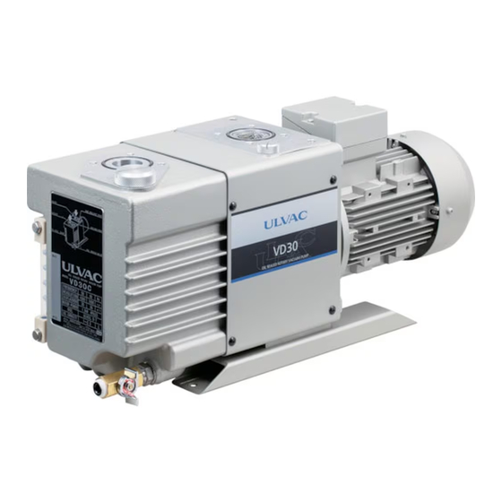
- Page 1 YK15-0009-DI-002-04 INSTRUCTION MANUAL OIL SEALED ROTARY VACUUM PUMP VD30C VD40C VD60C VD90C Before using this product, be sure to read this operation manual. Keep this manual with care to use at any time. ULVAC, Inc. Components Division http://www.ulvac.co.jp/...
- Page 5 The performance and safety of this product might not be ensured if any of the devices put together did not conform to same regulations or this product itself was modified. ULVAC shall be not liable to guarantee performance and safety in such cases above. Any modification of this product by the user is out of the scope of guarantee by us and not be guaranteed in any manner.
-
Page 6: Safety Symbol Marks
IMPORTANT ② It is prohibited to use this instruction manual except for explanation when using the VD30C, VD40C, VD60C and VD90C and other purpose Components Division of ULVAC, Inc. agreed. ③ It is prohibited to hand over and disclose this instruction manual to third parties without agreement by Components Division of ULVAC, Inc. -
Page 7: Safety Precautions
YK15-0009-DI-002-04 0.3 Safety Precautions Descriptions are given as the method to keep away from danger and actions that must be restricted on the use of this product. Use of this product and this Instruction Manual. Please read this Instruction Manual before starting installation, operation check or maintenance of this product to use it in long term. - Page 8 YK15-0009-DI-002-04 Pump oil as well as the Pump unit becomes toxic should the toxic gas was sucked in the vacuum pump. Pay attention to execute maintenance work. DANGER We would be obliged to refrain from handling and/or executing maintenance of this product if the detail of used hazardous substance was not disclosed or this product has exhausted such substance that the detoxification process is hardly conducted.
- Page 9 Pump. Transfer ① You have a risk of giving damage to your back as the load larger than safety standard shall be required to transfer this product. VD30C: 58kg VD40C: 60kg VD60C: 90kg VD90C: 113kg...
- Page 10 YK15-0009-DI-002-04 Countermeasure to the earthquake There is a risk that the Pump lays down or slides and breaks peripheral units if it was not correctly fixed. Be sure to give allowances to the vacuum piping and electric cables so that they absorber vibrations to prevent them from breaking and/or dismantling.
- Page 11 YK15-0009-DI-002-04 Operation This pump is not pressure-proof. Do not run the Pump on blocking the exhaust outlet or putting any device that might hamper gas passage onto the outlet. There is a risk that the pressure inside the Vacuum pump rises up to cause break or oil leak of the casing or Oil level gauge resulting in overload of the motor.
- Page 12 ③ Make airtight completely the Pump exhaust outlet with a blank flange. Transfer ① You have a risk of giving damage to your back as the load larger than safety standard shall be required to transfer this product. VD30C: 58kg VD40C: 60kg VD60C: 90kg VD90C: 113kg...
-
Page 13: Types And Descriptions Of Warning Labels Displayed On This Machine And Displayed Positions
YK15-0009-DI-002-04 0.4 Types and Descriptions of Warning Labels Displayed on This Machine and Displayed Positions Warning labels are attached on the warning locations in this system. Be sure to check them before starting operation of the Pump. Before use, read through the instruction manual and fully understand its contents. - Page 14 YK15-0009-DI-002-04 Fig. 1 Warning Label This product can be used in compliance with the requirements of UL1450 "Standard for Motor-Operated Air Compressors, Vacuum Pumps, and Painting Equipment" by replacing the warning label according to the figure below. ①:Hazardous voltage. ②:Hot heating part present. ③:There is a risk of explosion.
-
Page 15: Acceptance And Storage Of The Pump
YK15-0009-DI-002-04 0.5 Acceptance and Storage of the Pump 0.5.1 Unpacking/Acceptance of the Pump ① This product is packed with the wooden frame. Please ask the special agency for dismantling it. Advise the dismantling agent to wear leather gloves and use appropriate tools such as pinch bar as they have a risk of cutting the hand by nail or chip. -
Page 16: Transfer
0.5.2 Transfer You have a risk of giving damage to your back as the load larger than ① safety standard shall be required to transfer this product. VD30C: 58kg VD40C: 60kg VD60C: 90kg VD90C: 113kg Be sure to use the loading machinery (such as mobile crane) to lift up... -
Page 17: Ambient Condition For Storage, Install And Operation
YK15-0009-DI-002-04 0.5.3 Ambient Condition for Storage, Install and Operation As precise clearances are provided with this machine, be sure to fulfill the following for its storage, install and operation; ① Ambient temperature and humidity for storage : -10°C to 50°C, less than 95%RH ②... -
Page 18: Protective Device
Fix the Pump horizontally so that there is not a wobble. Refer to “3.1 Storage/ Installation”, too. Anti-vibration Model Foot print Bolt Rubber mount VD30C VD40C VD60C The Pump has four holes. The Pump is fixed with four bolts. Kurashiki Kako., Ltd. More than Model:... -
Page 19: Table Of Contents
YK15-0009-DI-002-04 Table of Contents 0. Before Using This Product ........................i 0.1 Safety Symbol Marks ......................... ii 0.2 Meanings of Safety Symbol Marks ....................ii 0.3 Safety Precautions..........................iii 0.4 Types and Descriptions of Warning Labels Displayed on This Machine and Displayed Positions . ix 0.5 Acceptance and Storage of the Pump .................... - Page 20 8.2 Duration of guarantee ........................49 8.3 Warrantee scope ..........................49 8.4 Response procedure ........................49 8.5 Disclaimer ............................50 8.6 Others ............................. 50 9. Main Replacement Parts ........................51 Request Form for Repair/Inspection of ULVAC Components /Certificate of Contamination SERVICE CENTER Contents-2...
- Page 21 Fig. 10 Dimensional drawing VD60C-H....................12 Fig. 11 Dimensional drawing VD90C-H ....................12 Fig. 12 Pumping speed curves - MODEL VD30C/VD40C ............... 14 Fig. 13 Pumping speed curves - MODEL VD60C/VD90C ............... 14 Fig. 14 Lubrication and oil level indication ....................17 Fig.
-
Page 22: For Your Safety Use
② There is a risk that the Pump might drop down when attempted the Pump weight unreasonable operation or machinery VD30C: 58kg setup was not sufficient. You are strictly restricted from entering VD40C: 60kg beneath the Pump. VD60C: 90kg VD90C: 113kg... -
Page 23: Warning Electric Shock
YK15-0009-DI-002-04 1.1.3 ! Warning Electric shock Factors Avoidance methods and measures ① Be sure to cut the electricity to do electrical connection. ② Never fail to take the earth connection. ③ Ensure to close the cover of motor terminal box and never open it during Getting electrical shock operation. -
Page 24: Safety Data Sheet(Sds
YK15-0009-DI-002-04 1.2 Safety Data Sheet(SDS) Chemical material used for this Pump; (1) ULVOIL R-72 (Standard) (2) ULVOIL R-42(For cold district in winter、 In the case of ambient temperature 4-10℃) IMPORTANT The Safety Data Sheet introduces the chemical material potential to use or touch on operating this machine. -
Page 25: Pump Outline
YK15-0009-DI-002-04 2. Pump Outline 2.1 Characteristics The VD30C, VD40C, VD60C and VD90C are a compact, low noise, two-stage vacuum pump that permits high speed rotation. Features of this pump include the following: (1) High maintainability Pump main body section unit can be dismounted and remounted simply by removing the side panel when there is no piping on the exhaust side (it is not necessary to disconnect the motor or remove the piping from the intake port). - Page 26 Optional specification for special application Following specification is available to meet various applications. Table. 3 Optional specifications and gasket material/oil type comparison table Applicable Model Oil seal Specification O-ring Oil type *1 VD30C VD60C Wetted Atmosphere VD40C VD90C surface side...
- Page 27 YK15-0009-DI-002-04 【Spec. F】 Fluorine oil is used as lubricating oil The Spec. F uses extremely chemically stable and inert fluorine oil as a countermeasure against oil deterioration caused by corrosive, combustible, and oxidizing gases. Fluorine oil cannot be replaced with mineral oil (ULVOIL R-72). At the factory, assembly inspection is performed using fluorinated oil, but we do not ship products with fluorinated oil.
-
Page 28: Performance Specifications
YK15-0009-DI-002-04 2.2 Performance Specifications Table. 4 Specifications Specifications Model VD30C VD40C VD60C VD90C Designed pumping speed 50Hz L/min 1000 1500 17.66 23.54 35.31 52.97 60Hz L/min 1200 1800 21.29 28.25 42.38 63.57 Ultimate Gas ballast port close 0.67 pressure Torr 5×10... -
Page 29: System Flow
YK15-0009-DI-002-04 2.3 System Flow Power supply is required. And you prepare wiring, safety circuit and exhaust processing equipment, etc. Fig. 3 Location of vacuum pump in host device... -
Page 30: Dimensional Drawing
YK15-0009-DI-002-04 2.4 Dimensional drawing Fig. 4 Dimensional drawing VD30C, VD30C-F, VD30C-N Fig. 5 Dimensional drawing VD40C, VD40C-F, VD40C-N... - Page 31 YK15-0009-DI-002-04 Fig. 6 Dimensional drawing VD60C Fig. 7 Dimensional drawing VD90C...
- Page 32 YK15-0009-DI-002-04 Fig. 8 Dimensional drawing VD30C-H, VD30C-B Fig. 9 Dimensional drawing VD40C-H, VD40C-B...
- Page 33 YK15-0009-DI-002-04 Fig. 10 Dimensional drawing VD60C-H Fig. 11 Dimensional drawing VD90C-H...
-
Page 34: Pump Performance
Pump in a state not introducing any gas through the suction inlet (no load operation).” ULVAC measures the value by the Pirani gauge connected to the Pump suction inlet using the specified vacuum pump oil after having completely blocked out the Pump unit from the system. - Page 35 Pumping Speed (JIS B 8316/1985) :ULVOIL R-72 Gauge:Pirani Gauge:Capasitance Manometer 1000 10000 100000 Pressure [Pa] Fig. 12 Pumping speed curves - MODEL VD30C/VD40C Gas Ballast Closed VD90C 60Hz Gas Ballast Opened VD90C 50Hz VD60C 60Hz VD60C 50Hz Pumping Speed (JIS B 8316/1985)
-
Page 36: Power Requirements
YK15-0009-DI-002-04 2.5.3 Power Requirements Motive energy to drive the Vacuum pump is a total value of the work of the mechanical element on the rotary friction (mechanical work) and the work of compressing the air (compression work) that becomes maximum when the suction pressure is between 3×10 4×10 Pa. -
Page 37: Mounting
YK15-0009-DI-002-04 3. Mounting ① You are requested to install and operate this product in compliance with the laws and regulations relating to the safety, e.g. Fire Defense Law, Electric wiring regulation and so on in the country and region you use this product. Consequently you shall be requested to attend general safety lectures officially effective in the area, such as electrical safety, Cargo handling safety and so on. -
Page 38: Lubrication
SDS. CAUTION Ensure to use the vacuum pump oil designated by ULVAC. Operation using oil other than designated shall be out of our scope of guarantee as it might impair the Pump performance and shorten the life cycle. -
Page 39: Inlet Port Piping
Provide main valve, vacuum gauge and leak valve between the vacuum chamber and pump, as shown in Fig. 15. Fig. 15 Connection to vacuum chamber (example) Use the flange for connection between the Pump Inlet and the piping. MODEL Flange at the pipe VD30C JIS B 2290:1998 VF40 VD40C Vacuum technology-Flange dimensions; VD60C... -
Page 40: Outlet Port Piping
Use the flange for connection between the Pump Outlet and the piping. It is recommended to provide an oil mist trap to reduce oil consumption and to trap oil mist. MODEL Flange at the pipe VD30C JIS B 2290:1998 VD40C Vacuum technology-Flange dimensions;... -
Page 41: Electrical Connection
YK15-0009-DI-002-04 3.5 Electrical Connection Conduct the electrical connection referring to the Fig. 16, Fig.17 and Table.5.. Without changing motor, it is possible to run the Pumps both with 200V and 400V class utilities by changing wire connection in the motor terminal box because multi voltage motor, for both 200V and 400V classes, is used for this pump. - Page 42 YK15-0009-DI-002-04 ① Use crimping terminals for the connection and tighten screws. Check also screws fixing the connector tighten. ② Motor rotation direction is clockwise viewed from the motor side. Refer to the arrow mark castled on the Motor flange ③ Be sure also to put a safety circuit such as MCCB(Molded Case Circuit Breaker), MC(Magnetic Contactor) and THR(Thermal Relay) for the electrical connection.
- Page 43 YK15-0009-DI-002-04 ① Turn OFF the Power Supply to do the electrical connection. Never try to work on it on keeping the electricity turned ON. ② A correct wiring work must observe the law and the rule that relates safely. A wrong wiring work might start a fire. ③...
- Page 44 For Japan For America For Europe and China Size・Form N・m JST Corporation Δ settinng < 40m 1.2-1.5 R2-4 (Delta) Hexagon nut VD30C -5.5mm AWG14 AWG14-AWG10 2.5mm 2.5mm -6mm VD40C settinng < 125m Cross recessed 2.0-2.5 R2-5 (Star) head screw Δ...
-
Page 45: Operation
YK15-0009-DI-002-04 4. Operation 4.1 Caution on Operation This pump is not pressure-proof. ① Never run the Vacuum pump on blocking up the exhaust outlet, putting any device that hampers the gas passage. There is a risk that pressure in the Pump rises, and the main body of the Pump and the oil level gauge might explode, or the motor become an overload. - Page 46 YK15-0009-DI-002-04 ⑤ Caution shall be required for the operation under high pressure range. (1) In the continuous operation of VD90C, perform it in the inlet pressure at 1000Pa or less. The temperature of the Pump becomes very high temperature, and the Pump may break. (2) Continuous operation one hour or more under high pressure 1000Pa or more would increase the oil volume that are discharged as the oil mist and cause rapid parts wear or cause a...
-
Page 47: Operation Start
YK15-0009-DI-002-04 4.2 Operation Start Before starting the Pump, check the following again. (1) Piping and wire connection are completed. (2) Checking the oil level Ensure that the oil level is between the two level lines on the oil level gauge shown in Fig, 14. (3) Checking the rotating direction Close the main valve on the Inlet side, open the leak valve, and run the Pump for two to three seconds to check the rotating direction of the motor. -
Page 48: Operation Stop
YK15-0009-DI-002-04 4.3 Operation Stop (1) Close the main valve on the Inlet side, open the leak valve to vent the Pump to atmosphere, and stop the Pump. (2) Open the Suction leak valve to make atmospheric pressure inside the Pump. The Vacuum pump gets high temperature during operation. -
Page 49: Gas Ballast Function
YK15-0009-DI-002-04 4. 4 Gas Ballast Function This product is installed with the gas ballast function as standard. When using the gas ballast function depending on the application, the needle valve, the pipe and the like are connected to gas ballast port (G3/8).It is applicable to breathe in the condensed gas such as the steam and solution vapor. -
Page 50: The
YK15-0009-DI-002-04 The guaranteed pressure resistance of this pump is 0.03 MPa (0.3 kg / cm2) (gauge pressure). Operate the supply pressure of the gas ballast gas to be introduced within the following range. WARNING Supply pressure: Atmospheric pressure to 0.03 MPa (0.3 kg / cm2 (gauge pressure)) or less. -
Page 51: Oil Mist Trap (Optional)
YK15-0009-DI-002-04 4.6 Oil mist trap (Optional) The oil mist trap can be mounted to trap the oil mist discharged from the Pump. Pressure at the inlet 10000Pa or less 10000Pa or more VD30C/VD40C TM201 TM401 TM-2 VD60C/VD90C TM401 (With an adapter) For more information, please see the instructions OIL MIST TRAPS. -
Page 52: Maintenance And Check
YK15-0009-DI-002-04 5. Maintenance and Check 5.1 Maintenance You should check following points at least once per three days while you continue operation. Check the machine much more frequently during high overload operation (continuous operation at 1000Pa or more, repeated operation between atmospheric pressure and vacuum). (1) Whether the Vacuum oil pump oil volume is between two level lines or not. -
Page 53: Regular Check
YK15-0009-DI-002-04 5.2 Regular Check Although you have to consider checkpoints depending on the use of the Pump, you should check the following regularly; it is helpful to avoid trouble and extend the Pump life cycle. ① Check and ensure that any of hazardous energy is blocked before starting the operation. -
Page 54: Pump Oil Level Check
YK15-0009-DI-002-04 5.2.1 Pump Oil Level Check The Pump oil level should be between the two level lines (MAX and MIN on the Pump case) on the oil level gauge. (Refer to Fig.14) 5.2.2 Vacuum Pump Oil Check The Pump oil might deteriorate in a shorter time depending on the use. If substances of low boiling point (water, organic solvent, etc.) are mixed with pump oil or sludge collects on the bottom of the Pump case, the ultimate pressure cannot be recovered by one oil change, but the oil must be changed several times. - Page 55 YK15-0009-DI-002-04 ① Never fail to lubricate the machine. If the lubrication oil came down lower than limit level during operation, it might give damage on the bearing, gear and rod sealing and result in leak, noise, motor overload and operation stop. The Pump oil might deteriorate in a shorter time depending on the ⑥...
-
Page 56: Replace Vacuum Pump Oil
SDS. CAUTION Ensure to use the vacuum pump oil designated by ULVAC. Operation using oil other than designated shall be out of our scope of guarantee as it might impair the Pump performance and shorten the life cycle. -
Page 57: Oil Leak Check
YK15-0009-DI-002-04 5.2.4 Oil Leak Check The Pump system needs repair if occurred any oil leak from the Shaft sealing or Pump unit. Type of the seals and O-rings are listed at the end of this document. Please contact the Service Center close to you for purchase and repair. -
Page 58: Checking Coupling And Spider
YK15-0009-DI-002-04 5.2.8 Checking Coupling and Spider The spider of the coupling that connects the Pump body and the motor is made of rubber. Replace it if the spider is damaged. Please contact the closest Service center. Replace it once a year by rule of thumb. If the Pump is started and stopped several hundreds of times a day, however, shorten the replacement frequency. -
Page 59: Checking Oil Mist Trap (Option)
YK15-0009-DI-002-04 5.2.9 Checking Oil Mist Trap (option) To use the Oil mist trap, be cautious not to have clog of the filter element in the trap. Too much clog would prevent the exhaust gas from passing through the filter element, raise the pressure inside the Pump unit and might result in breaking it. -
Page 60: Checkup After Storage For A Long Period
YK15-0009-DI-002-04 5.3 Checkup after storage for a long period Long term storage of the Vacuum pump without operation might possibly cause trouble in operation caused by rust. If you kept the Pump long time without operating it, ask a closest Service Center for the check. -
Page 61: Trouble Shooting
YK15-0009-DI-002-04 5.5 Trouble shooting Table. 7 Troubleshooting Trouble Causes Processing Method Reference Motor connection is wrong. Check the connection. Safety circuit such as a Make the Safety circuit conform MS (Magnetic Switch) is to the Motor specification. not correctly set. Oil viscosity got higher. - Page 62 YK15-0009-DI-002-04 Trouble Causes Processing Method Reference Are the Safety circuit such as a MS (Magnetic Switch) Check the Safety circuit and and MCCB (Molded Case replace. Circuit Breaker) normal? Failure of components. Run only by the Motor. Is the Rotation and current Replace the Motor value correct? Moisture or solvents were...
- Page 63 YK15-0009-DI-002-04 Trouble Causes Processing Method Reference Motor rotation direction is Do the connection again to reverse. correct the rotation direction. The oil is not supplied by Control the oil level. the specified volume. Supply the oil by the specified volume. 5.2.1 Conduct the overhaul.
- Page 64 YK15-0009-DI-002-04 Trouble Causes Processing Method Reference Pump exhaust capacity is smaller compared to the Select another Pump type. Vacuum chamber capacity. Pressure measurement Measure correctly the pressure. 2.5.1 method is wrong. Use the Vacuum gauge that matches the measurement Vacuum gauge is not pressure range and correctly 2.5.1 pressure...
- Page 65 Pump. does not stop it. decline, and Conduct the overhaul of the Not using the ULVAC 5.2.1 Pump and replace the oil with genuine oil. Pumping the ULVAC oil. 5.2.2...
- Page 66 YK15-0009-DI-002-04 Trouble Causes Processing Method Reference Keeping continuous Pump surface temperature would rise up around 100℃ on operation under high suction pressure. continuous operation under high suction pressure. The oil is not supplied by Control the oil level. the specified volume. Supply the oil by the specified volume.
- Page 67 YK15-0009-DI-002-04 Trouble Causes Processing Method Reference Deterioration of the O-ring and/or oil seal of the Case Conduct the overhaul. Oil leaks to and Cover. the outside of the Oil inlet is loose. Tighten again the oil inlet. Pump. The drain port is Re-tighten the drain port.
-
Page 68: Removal / Transport
③ Keep applying a plate displaying the name of exhausted gas on a place easily seen on the Pump. ① You have a risk of giving damage to your back as the load larger than safety standard shall be required to transfer this product. VD30C: 58kg VD40C: 60kg VD60C: 90kg VD90C: 113kg... -
Page 69: Disposal
YK15-0009-DI-002-04 7. Disposal Make sure to keep in compliance with the laws and regulations established by the local governments to dispose the Vacuum pump. You should ask the dedicated disposal agency for the disposal particularly if the Pump has exhausted any toxic gas. Note that you are requested to bear the cost and charges relating to the disposal. -
Page 70: Warranty Clauses
8.4 Response procedure (1) Domestic business in Japan: ULVAC send a replacement or Buyer return the defective items to ULVAC, Inc. or to the local ULVAC representatives for repair. If field service is required, Buyer shall ask ULVAC, Inc. or the local ULVAC representatives. -
Page 71: Disclaimer
(7) Secondary damage by defect of this Product defect. (8) Secondary damage to Buyer by the reason that third party sued ULVAC for patent infringement. (9) ULVAC engineer decided the reason of failure was improper use which does not conform to the use condition of this Product. -
Page 72: Main Replacement Parts
YK15-0009-DI-002-04 9. Main Replacement Parts * : Different parts between VD30C/VD40C and VD60C/VD90C Fig. 20 Exploded perspective view... - Page 73 Q'ty Descriptions Drawing No. Descriptions Drawing No. Descriptions Drawing No. Descriptions Drawing No. VD30C VD40C VD60C VD90C VD30C VD40C VD60C VD90C VD30C VD40C VD60C VD90C VD30C VD40C VD60C VD90C Intermediate case KA9002-021-01 18 2nd rotor shaft KA9002-023-02 40 O-ring pipe...
- Page 74 YK15-0009-DI-002-04 Table. 9 Main replacement parts list (VD30C/VD40C) VD30C VD30C-A VD30C-B VD30C-H VD40C VD40C-A VD40C-B VD40C-H Location Parts No. Description Specification Material Q'ty Material Q'ty Material Q'ty Material Q'ty Silicone rubber Oil seal Shaft ← ← ← For VD30C Resin 1st Vane ←...
- Page 75 YK15-0009-DI-002-04 Table. 10 Main replacement parts list (VD60C/VD90C) VD60C VD90C VD60C-H VD90C-H Location Parts No. Description Specification Material Q'ty Material Q'ty Material Q'ty Material Q'ty Oil seal ← ← ← Shaft ← ← ← For VD60C Resin 1st Vane ← ←...
- Page 76 YK15-0009-DI-002-04 This mark is applied to the electronic information product sold in the People's Republic of China. The figure at the center of the mark is the validity date of environmental protection. This product does not influence the environment, the human body and the property during the period reckoning the manufacturing date as long as the caution for safe use regarding the products are observed.
- Page 77 ULVAC service center or sales office prior to shipment. Please consult with your closest local ULVAC service center or sales office if our components are used with toxic gases or contaminated with reactive products or substances produced by reaction.
Need help?
Do you have a question about the VD30C and is the answer not in the manual?
Questions and answers