Sign In
Upload
Manuals
Brands
Bender Manuals
Measuring Instruments
isoMED427
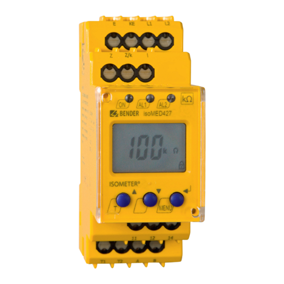
Bender isoMED427 Monitoring Device Manuals
Manuals and User Guides for Bender isoMED427 Monitoring Device. We have
4
Bender isoMED427 Monitoring Device manuals available for free PDF download: Manual
Bender isoMED427 Manual (88 pages)
Insulation fault locator to locate insulation faults in ungrounded DC, AC and three-phase power supplies
Brand:
Bender
| Category:
Industrial Electrical
| Size: 21.79 MB
Table of Contents
Table of Contents
3
General Information
7
How to Use the Manual
7
Indication of Important Instructions and Information
7
Signs and Symbols
7
Service and Support
7
Training Courses and Seminars
8
Delivery Conditions
8
Inspection, Transport and Storage
8
Warranty and Liability
8
Disposal of Bender Devices
9
Safety
9
Function
10
Intended Use
10
Features
10
Areas of Application
10
Standards
10
System Variants
11
System Properties
11
Compatibility
12
Operating Principle of the EDS System
13
Schematic Diagram of an EDS System
15
Device Overview
16
External Dimensions of EDS44
16
View and Connections of EDS44
17
View and Connections of EDS44
18
Mounting
19
General Information
19
Installation Clearances
19
Screw Mounting
20
DIN Rail Mounting
21
Connection of the BB Bus
21
Connection to the Voltage Supply
22
Connection of the X1 Interface (I1, I2, A, B, M
22
Connection of the Relays
23
BS Bus Termination
23
Connection of the X2 Interface (K1-12/L1-12)
24
Connection of CTAC
24
Connection of Measuring Current Transformer CTBC
26
Connection of CTAF
27
Connection to a 3(N)AC System
28
Connection to an AC System
29
Connection to a DC System
30
Connection Example: ISOMETER® Iso685-D-P, EDS440-S, IOM441-S and EDS440-L
31
Display and Alarm Messages
32
Display Elements EDS44
32
Operating and Display Elements EDS44
32
Standard Display in Operating Mode
33
Standard Display EDS44
33
Alarm Messages
34
Insulation Fault (ALARM IΔL )
34
Residual Current Exceeded (ALARM I Δn )
35
Connection Fault of the Current Transformers
35
Device Error, BB Bus Error
36
Device Error, Failure BS Bus Master
37
Error Message
37
Acoustic Alarm Message
37
Commissioning
38
Requirements for Reliable Insulation Fault Location
38
Before Switching on
38
Switching on
39
Steps for Commissioning ISOMETER® and EDS
39
Periodic Verification
40
Device Communication
41
RS-485 Interface
41
Bender Sensor Bus (BS Bus)
41
Modbus RTU
42
Operation
43
Reading out and Setting the BS Address
43
Reading out a BS Address
43
Setting a BS Address
44
Extended Address Range (Offset = 80)
46
Display and Change of Transmission Protocols
47
Displaying the Current Transmission Protocol
47
Changing the Transmission Protocol
48
Resetting Saved Alarm Messages (RESET Button)
48
Deactivating the Buzzer (EDS44
48
Running a Test (TEST Button)
48
Settings
50
EDS Settings on the ISOMETER
50
Locating Current Injector Settings
50
Trigger Function
51
Fault Memory
51
Settings of Inputs and Outputs of the EDS44
51
Digital Inputs of the EDS44
51
Digital Outputs of the EDS44
52
Factory Settings
54
Alarm Messages
56
Diagrams
57
Response Sensitivity Curves
57
Characteristic Curves EDS440 for 3AC Systems
58
Characteristic Curves EDS440 for AC Systems
60
Characteristic Curve of EDS440 for Low Voltages in DC, AC and 3NAC Systems
61
Characteristic Curves EDS440 for DC Systems
62
Characteristic Curves EDS441 for AC Systems
65
Characteristic Curves EDS441 for DC Systems
66
Characteristic Curves of EDS441-LAB for AC Systems
68
Characteristic Curves EDS441-LAB for DC Systems
69
Response Values of EDS440-LAF for DC Systems
71
Response Values of EDS440-LAF for AC Systems
71
Fault Curve EDS440 and EDS441
72
Technical Data
73
Technical Data ISOSCAN® EDS440 and EDS441
73
Standards and Certifications
79
Ordering Data
80
Insulation Fault Locators
80
Accessories
80
Measuring Current Transformers
81
Change History
83
Advertisement
Bender isoMED427 Manual (36 pages)
Insulation monitoring device for medical applications
Brand:
Bender
| Category:
Measuring Instruments
| Size: 2.62 MB
Table of Contents
Table of Contents
3
General Instructions
5
How to Use this Manual
5
Indication of Important Instructions and Information
5
Signs and Symbols
5
Training Courses and Seminars
6
Delivery Conditions
6
Inspection, Transport and Storage
6
Warranty and Liability
6
Disposal of Bender Devices
7
Safety
7
Device-Speci C Safety Information
8
Intended Use
8
Functional Description
9
Alarm and Operating Messages for each BMS Channel
10
Mounting and Connection
12
Wiring Diagram
13
Commissioning
14
Operating Elements
15
Display Elements Isomed427X-(PT)
16
Display in Standard Mode
16
Alarm Indication and EDS Activity
17
Parameter Settings
18
Menu Overview
19
Setting the Response Value (<R) (<(<R))
20
Setting the Response Value for Load Current Monitoring
20
Setting the Response Value Overtemperature ( >°C) (Isomed427P-PT)
20
Setting the Operating Principle of the Alarm Relay
20
Setting the BMS Address
20
Activating Automatic Insulation Fault Location
21
Password Protection
21
Deactivating the CT Monitoring Function
22
Resetting the Device to Factory Settings
22
Querying Device Information
23
Technical Data Isomed427(P)-(PT)
24
Factory Settings Isomed427X-(PT)
29
Device Overview
30
Recommended Device Combinations
31
Standards and Certi Cations
31
Bender isoMED427 Manual (28 pages)
Insulation monitoring device for medical applications
Brand:
Bender
| Category:
Measuring Instruments
| Size: 3.37 MB
Table of Contents
Table of Contents
3
1 General Information
5
How to Use the Manual
5
Indication of Important Instructions and Information
5
Signs and Symbols
5
Service and Support
5
Training Courses and Seminars
6
Delivery Conditions
6
Inspection, Transport and Storage
6
Warranty and Liability
6
Disposal of Bender Devices
7
Safety
7
2 Device-Specific Safety Information
8
Intended Use
8
3 Functional Description
9
Alarm and Operating Messages for each BMS Channel
10
4 Mounting and Connection
11
Wiring Diagram
12
Commissioning
12
5 Operating Elements
13
Display Elements Isomed427X-(PT)
13
Display in Standard Mode
14
Alarm Indication and EDS Activity
14
6 Parameter Settings
15
Menu Overview
16
Setting the Response Value R an (<R)
17
Setting the Response Value for Load Current Monitoring
17
Setting the Response Value Overtemperature ( >°C) (Isomed427P-PT)
17
Setting the Operating Principle of the Alarm Relay
17
Setting the BMS Address
17
Activating Automatic Insulation Fault Location
17
Password Protection
17
Deactivating the CT Monitoring Function
18
Resetting the Device to Factory Settings
19
Querying Device Information
19
7 Technical Data Isomed427(P)-(PT)
20
Factory Settings Isomed427X-(PT)
24
Ordering Data
25
Recommended Device Combinations
25
Standards and Certifications
25
Change Log
26
Advertisement
Bender isoMED427 Manual (12 pages)
Insulation monitoring device
Brand:
Bender
| Category:
Measuring Instruments
| Size: 3.46 MB
Table of Contents
Montage und Anschluss
3
Installation and Connection
3
Wiring Diagram
4
Anzeige- und Bedienelemente
5
Display and Operating Elements
5
Querying Device Information
9
Technische Daten
9
Technical Data
9
Ordering Information
11
Advertisement
Related Products
Bender isoMED427P
Bender isoMED427P-CX
Bender ISOMETER IRDH275
Bender ISOMETER IRDH275B Series
Bender ISOMETER isoPV with AGH-PV
Bender ISOMETER IR1570W-435
Bender ISOMETER IR1570-434
Bender ISOMETER IR1575-435
Bender ISOMETER IR1575W-435
Bender ISOMETER IR1575-434
Bender Categories
Measuring Instruments
Monitor
Control Unit
Control Panel
Relays
More Bender Manuals
Login
Sign In
OR
Sign in with Facebook
Sign in with Google
Upload manual
Upload from disk
Upload from URL