Table of Contents
Advertisement
Quick Links
USER GUIDE
SCC-TC Series Thermocouple
Input Modules
Conventions
<>
»
Download from Www.Somanuals.com. All Manuals Search And Download.
The SCC-TC Series thermocouple input modules, SCC-TC01 and
SCC-TC02, accept input signals from B-, E-, J-, K-, N-, R-, S-, and T-type
thermocouples. The thermocouple inputs are filtered and passed into a
differential amplifier with a gain of 100. The output of the amplifier passes
through a dual-pole 2 Hz filter. Each module contains thermistor circuitry,
powered by a 2.5 V reference, to compensate for cold-junction effects.
Each module also can detect open thermocouple circuits.
Alternatively, you can connect voltage signals up to ±100 mV to the screw
terminals of the SCC-TC02 and use it as a low-bandwidth millivolt-input
module.
The following conventions are used in this guide:
Angle brackets that contain numbers separated by an ellipsis represent
a range of values associated with a bit or signal name—for example,
ai<0..7>.
The » symbol leads you through nested menu items and dialog box options
to a final action. The sequence File»Page Setup»Options directs you to
pull down the File menu, select the Page Setup item, and select Options
from the last dialog box.
This icon denotes a note, which alerts you to important information.
This icon denotes a caution, which advises you of precautions to take to
avoid injury, data loss, or a system crash. When this symbol is marked on
the product, refer to the Read Me First: Safety and Radio-Frequency
Interference document, shipped with the product, for precautions to take.
Advertisement
Table of Contents

Related Manuals for National Instruments SCC-TC Series


Summary of Contents for National Instruments SCC-TC Series
- Page 1 USER GUIDE SCC-TC Series Thermocouple Input Modules The SCC-TC Series thermocouple input modules, SCC-TC01 and SCC-TC02, accept input signals from B-, E-, J-, K-, N-, R-, S-, and T-type thermocouples. The thermocouple inputs are filtered and passed into a differential amplifier with a gain of 100. The output of the amplifier passes through a dual-pole 2 Hz filter.
-
Page 2: What You Need To Get Started
SCC-PWR03 (requires a 7 to 42 VDC power supply, not included) ❑ One or more SCC-TC0X modules ❑ SCC-TC Series Thermocouple Input Modules User Guide ❑ Read Me First: Safety and Radio-Frequency Interference ❑ SC-2345 User Manual, available online at ni.com... -
Page 3: Unpacking The Module
Refer to the Read Me First: Safety and Radio-Frequency Interference document Caution before removing equipment covers or connecting/disconnecting any signal wires. © National Instruments Corporation SCC-TC Series Thermocouple Input Modules User Guide Download from Www.Somanuals.com. All Manuals Search And Download. -
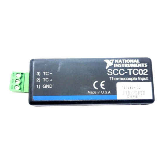
Page 4: Connecting The Input Signals
The screw-terminal connector provides a ground connection for shielded thermocouples. Otherwise, the two modules function identically. To use an SCC-TC01, plug the male thermocouple connector into the module. SCC-TC Series Thermocouple Input Modules User Guide ni.com Download from Www.Somanuals.com. All Manuals Search And Download. - Page 5 For ANSI color-coded J-type thermocouples, the red wire is negative and the white wire is positive. Refer to the thermocouple data sheet if possible. You can find information about other color-coding schemes in the NI KnowledgeBase at ni.com/ support © National Instruments Corporation SCC-TC Series Thermocouple Input Modules User Guide Download from Www.Somanuals.com. All Manuals Search And Download.
- Page 6 0 to 55 °C temperature range. NI-DAQ includes thermistor conversion utilities that implement the equations listed Note below. Refer to your software documentation for more information on these utilities. SCC-TC Series Thermocouple Input Modules User Guide ni.com Download from Www.Somanuals.com. All Manuals Search And Download.
- Page 7 If you are using an SCC-TC02 with an uncompensated SCC panelette, temperature gradients between the module and the junctions on the panelette affect the accuracy of your measurements. © National Instruments Corporation SCC-TC Series Thermocouple Input Modules User Guide Download from Www.Somanuals.com. All Manuals Search And Download.
- Page 8 Measurement & Automation Explorer (MAX) Configuration Run MAX to configure the SCC system. Complete one of the following procedures depending on the version of NI-DAQ used in your application. SCC-TC Series Thermocouple Input Modules User Guide ni.com Download from Www.Somanuals.com. All Manuals Search And Download.
- Page 9 Expand Traditional NI-DAQ Devices. Right-click the E Series DAQ device connected to the SC-2345, and select Properties. Select the Accessory tab. © National Instruments Corporation SCC-TC Series Thermocouple Input Modules User Guide Download from Www.Somanuals.com. All Manuals Search And Download.
- Page 10 You can select blocks of channels by pressing the <Shift> key while making the selections, or select individual channels by pressing the <Ctrl> key while making the selections. SCC-TC Series Thermocouple Input Modules User Guide ni.com Download from Www.Somanuals.com. All Manuals Search And Download.
- Page 11 While acquiring data on the selected channel, use a screwdriver to adjust the potentiometer protruding through the top of the module until you read 0 VDC. © National Instruments Corporation SCC-TC Series Thermocouple Input Modules User Guide Download from Www.Somanuals.com. All Manuals Search And Download.
- Page 12 Read the thermocouple channel on the E Series DAQ device [CH(X)]. ESERIES Calculate the thermocouple voltage by using the following formula: ESERIES -------------------- - SCC-TC Series Thermocouple Input Modules User Guide ni.com Download from Www.Somanuals.com. All Manuals Search And Download.
-
Page 13: Specifications
Input signal range........±100 mV Input impedance........10 MΩ powered on, 10 kΩ powered off or overload Bandwidth ..........2 Hz © National Instruments Corporation SCC-TC Series Thermocouple Input Modules User Guide Download from Www.Somanuals.com. All Manuals Search And Download. -
Page 14: Measurement Accuracy
±5 µV, and reference junction measurement accuracy of 0.5 °C. Assumes averaging. Non-averaged, single-point reading has an additional uncertainty (up to ±0.1 °C for J-type thermocouple). SCC-TC Series Thermocouple Input Modules User Guide ni.com Download from Www.Somanuals.com. All Manuals Search And Download. -
Page 15: Cold-Junction Sensor
Analog power ......... 60 mW max +15 V ..........2 mA max –15 V..........2 mA max Digital power (+5 V)......0.0 mW © National Instruments Corporation SCC-TC Series Thermocouple Input Modules User Guide Download from Www.Somanuals.com. All Manuals Search And Download. - Page 16 • IEC 61010-1, EN 61010-1 • UL 3111-1, UL 61010B-1 • CAN/CSA C22.2 No. 1010.1 SCC-TC Series Thermocouple Input Modules User Guide ni.com Download from Www.Somanuals.com. All Manuals Search And Download.
-
Page 17: Electromagnetic Compatibility
To obtain the DoC for this product, visit , search by model number or product line, and click the ni.com/hardref.nsf appropriate link in the Certification column. © National Instruments Corporation SCC-TC Series Thermocouple Input Modules User Guide Download from Www.Somanuals.com. All Manuals Search And Download. -
Page 18: I/O Connector Pin Assignments
Table 1. SCC Module Pin Signal Connections for SCC-TC0X Modules Pin Number Signal ACH(X) — — ACH(X+8) — AIGND — — — — AGND REF5V SCC-TC Series Thermocouple Input Modules User Guide ni.com Download from Www.Somanuals.com. All Manuals Search And Download. - Page 19 Table 1. SCC Module Pin Signal Connections for SCC-TC0X Modules (Continued) Pin Number Signal +15 V –15 V — — — — — — © National Instruments Corporation SCC-TC Series Thermocouple Input Modules User Guide Download from Www.Somanuals.com. All Manuals Search And Download.
- Page 20 *323099B-01* Corporation. Product and company names mentioned herein are trademarks or trade names of their respective companies. For patents covering National Instruments products, refer to the appropriate location: Help»Patents in your software, the patents.txt file on your CD, or ni.com/patents.
- Page 21 Free Manuals Download Website h p://myh66.com h p://usermanuals.us h p://www.somanuals.com h p://www.4manuals.cc h p://www.manual-lib.com h p://www.404manual.com h p://www.luxmanual.com h p://aubethermostatmanual.com Golf course search by state h p://golfingnear.com Email search by domain h p://emailbydomain.com Auto manuals search h p://auto.somanuals.com TV manuals search h p://tv.somanuals.com...
Need help?
Do you have a question about the SCC-TC Series and is the answer not in the manual?
Questions and answers