Table of Contents
Advertisement
Quick Links
USER GUIDE
SCC-TC Series Thermocouple
Input Modules
Alternatively, you can use the SCC-TC02 as a 2 Hz lowpass bandwidth ±100 mV
Note
input module.
Conventions
»
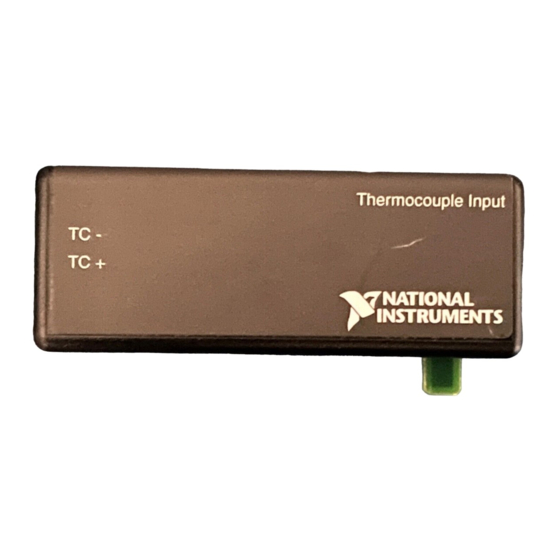
The SCC-TC Series thermocouple input modules, SCC-TC01 and
SCC-TC02, accept input signals from B-, E-, J-, K-, N-, R-, S-, and T-type
thermocouples. Each module contains thermistor circuitry powered by
2.5 V, to compensate for cold-junction effects and can detect open
thermocouple circuits. Each module has one thermocouple input channel,
which consists of a gain of 100 differential amplifier and a dual-pole 2 Hz
filter.
The following conventions are used in this guide:
The » symbol leads you through nested menu items and dialog box options
to a final action. The sequence File»Page Setup»Options directs you to
pull down the File menu, select the Page Setup item, and select Options
from the last dialog box.
This icon denotes a note, which alerts you to important information.
This icon denotes a caution, which advises you of precautions to take to
avoid injury, data loss, or a system crash. When this symbol is marked on
the product, refer to the Read Me First: Safety and Radio-Frequency
Interference document, shipped with the product, for precautions to take.
When symbol is marked on a product, it denotes a warning advising you to
take precautions to avoid electrical shock.
When symbol is marked on a product, it denotes a component that may be
hot. Touching this component may result in bodily injury.
Advertisement
Table of Contents

Subscribe to Our Youtube Channel
Related Manuals for National Instruments SCC-TC Series


Summary of Contents for National Instruments SCC-TC Series
- Page 1 USER GUIDE SCC-TC Series Thermocouple Input Modules The SCC-TC Series thermocouple input modules, SCC-TC01 and SCC-TC02, accept input signals from B-, E-, J-, K-, N-, R-, S-, and T-type thermocouples. Each module contains thermistor circuitry powered by 2.5 V, to compensate for cold-junction effects and can detect open thermocouple circuits.
- Page 2 SC-2345 SC-2345 refers to both the SC-2345 connector block and the SC-2345 configurable connector. SCC refers to any SCC series signal conditioning module. SCC-TC Series Thermocouple Input Modules User Guide ni.com...
-
Page 3: What You Need To Get Started
– SCC-PWR03 (requires a 7 to 42 VDC power supply, not included) ❑ One or more SCC-TC0X modules ❑ SCC-TC Series Thermocouple Input Modules User Guide ❑ Read Me First: Safety and Radio-Frequency Interference ❑ SC-2345/2350 User Manual, available at ni.com... -
Page 4: Device Specific Information
Sockets J9 to J16 also are available for digital input/output (DIO) conditioning or control. Refer to the SC-2345 User Manual for more information on configuring, connecting, and installing SCC modules SCC-TC0X dual-stage configuration is only available in NI-DAQ 7.1 or later. Note SCC-TC Series Thermocouple Input Modules User Guide ni.com... -
Page 5: Connecting The Input Signals
For ANSI color-coded J-type thermocouples, the red wire is negative and the white wire is positive. Refer to the thermocouple data sheet if possible. You can find information about other color-coding schemes in the NI KnowledgeBase at ni.com/ support © National Instruments Corporation SCC-TC Series Thermocouple Input Modules User Guide... - Page 6 0.1 µF at 25 16 V 2.5 kΩ Figure 1. SCC-TC0X Signal Connections For more information about how to configure the SCC-TC module using NI-DAQmx, refer to the SCC Quick Start Guide. SCC-TC Series Thermocouple Input Modules User Guide ni.com...
- Page 7 4 to a temperature. Use the polynomial expressions applicable to the type of thermocouple you are using. This calculation gives you a linearized temperature measurement. Polynomials are from NIST Monograph 175. Note © National Instruments Corporation SCC-TC Series Thermocouple Input Modules User Guide...
- Page 8 If your application demands extremely high accuracy, you can eliminate these errors by calibrating the system. Refer to the Calibrating System Offsets section for more information. SCC-TC Series Thermocouple Input Modules User Guide ni.com...
-
Page 9: Cold-Junction Sensor
For the cold-junction sensor measurement accuracy, refer to the Specifications section. For more information about how to configure the SCC-TC using NI-DAQmx, refer to the SCC Quick Start Guide. © National Instruments Corporation SCC-TC Series Thermocouple Input Modules User Guide... - Page 10 Convert the measured calibrator voltage to a temperature measurement as described in the Scaling Voltage Measurements section. Adjust the potentiometer on the top of the SCC-TC0X so that the measured temperature is equal to the calibration temperature. SCC-TC Series Thermocouple Input Modules User Guide ni.com...
-
Page 11: Specifications
Offset stability........±0.6 µV/°C max Nonlinearity ........... ±0.004% max Recommended warm-up time ....5 min Temperature range is 23 °C ±5 °C. Temperature range is 0 to 50 °C. © National Instruments Corporation SCC-TC Series Thermocouple Input Modules User Guide... -
Page 12: Measurement Accuracy
PCI/AT-MIO-16XE-50 one-year accuracy specification of 0.01% ±412 µV. SCC-TC01/02 accuracy specification of 0.08% ±5 µV, and reference junction measurement accuracy of 0.5 °C. Assumes averaging. Non-averaged, single-point reading has an additional uncertainty (up to ±0.1 °C for J-type thermocouple). SCC-TC Series Thermocouple Input Modules User Guide ni.com... -
Page 13: Open Thermocouple Detection
(SCC-TC02) ........ 28 to 16 AWG Maximum Working Voltage Maximum working voltage refers to the signal voltage plus the common-mode voltage. Each input must remain within ±12 V of chassis ground. Installation Category I © National Instruments Corporation SCC-TC Series Thermocouple Input Modules User Guide... -
Page 14: Electromagnetic Compatibility
CE Compliance The SCC-TC0X meets the essential requirements of applicable European Directives, as amended for CE marking, as follows: Low-Voltage Directive (safety)....73/23/EEC Electromagnetic Compatibility Directive (EMC) ........89/336/EEC SCC-TC Series Thermocouple Input Modules User Guide ni.com... -
Page 15: I/O Connector Pin Assignments
AI GND and A GND connect to the SC-2345 at the SCC-PWR connector. Table 1. SCC Module Pin Signal Connections for SCC-TC0X Modules Pin Number Signal AI (X) — — AI (X+8) — AI GND © National Instruments Corporation SCC-TC Series Thermocouple Input Modules User Guide... - Page 16 *371074B-01* Corporation. Product and company names mentioned herein are trademarks or trade names of their respective companies. For patents covering National Instruments products, refer to the appropriate location: Help»Patents in your software, the patents.txt file on your CD, or ni.com/patents.
Need help?
Do you have a question about the SCC-TC Series and is the answer not in the manual?
Questions and answers