Table of Contents
Advertisement
Quick Links
GETTING STARTED GUIDE
sbRIO-9687
General Purpose Inverter Controller Universal Interface Board
This document describes how to install and begin using the sbRIO-9687 GPIC Universal
Interface Board.
Contents
Safety Guidelines...................................................................................................................... 1
Unpacking the Kit..................................................................................................................... 2
Verifying the Kit Contents........................................................................................................ 2
Hardware Overview.................................................................................................................. 4
Dimensions................................................................................................................................4
Power........................................................................................................................................ 5
Preparing the Environment....................................................................................................... 6
Mounting the Hardware............................................................................................................ 6
Required Tools.................................................................................................................. 6
Installing the Thermal Kit and the sbRIO-9607................................................................7
Mounting the sbRIO-9683 or sbRIO-9684 ...................................................................... 8
Mounting the sbRIO-9687................................................................................................ 9
Surface Mounting Dimensions........................................................................................11
Connecting the sbRIO-9687....................................................................................................13
Connecting the Power..................................................................................................... 13
Powering on the sbRIO-9687..........................................................................................14
Connecting the sbRIO-9607 to the Host Computer........................................................ 14
Troubleshooting...................................................................................................................... 14
Where to Go Next................................................................................................................... 16
Related Documentation...........................................................................................................16
Worldwide Support and Services............................................................................................ 17
Safety Guidelines
Caution
document. Product misuse can result in a hazard. You can compromise the safety
protection built into the product if the product is damaged in any way. If the product
is damaged, return it to NI for repair.
Caution
marking compliance claims for the sbRIO-9687. The end-product supplier is
responsible for conformity to any and all compliance requirements.
Do not operate the sbRIO-9687 in a manner not specified in this
NI makes no product safety, electromagnetic compatibility (EMC), or CE
Advertisement
Table of Contents

Related Manuals for National Instruments sbRIO-9687


Summary of Contents for National Instruments sbRIO-9687
-
Page 1: Table Of Contents
GETTING STARTED GUIDE sbRIO-9687 General Purpose Inverter Controller Universal Interface Board This document describes how to install and begin using the sbRIO-9687 GPIC Universal Interface Board. Contents Safety Guidelines........................1 Unpacking the Kit........................2 Verifying the Kit Contents......................2 Hardware Overview........................4 Dimensions..........................4... -
Page 2: Unpacking The Kit
Caution The sbRIO-9687 is designed for non-hazardous live signals. You must ensure that all signals connected to the sbRIO-9687 are isolated from hazardous live circuits and no unsafe voltages are present at the sbRIO-9687 inputs. Voltages that exceed the specifications could result in damage to the sbRIO-9687. - Page 3 Thermal Kit for NI sbRIO-9607/9627/9637 Installation and Specifications Manual Some of the mounting hardware included with the OEM kits and the sbRIO Thermal Kit is not required for this mounting procedure. sbRIO-9687 Getting Started Guide | © National Instruments | 3...
-
Page 4: Hardware Overview
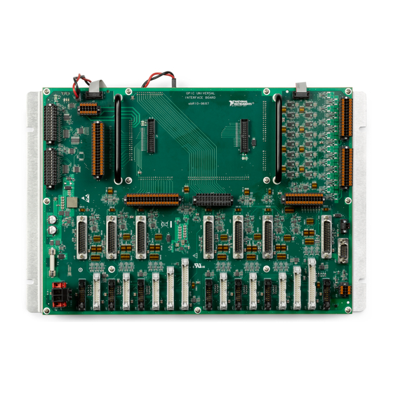
Hardware Overview The sbRIO-9687 is intended to be used together with the sbRIO-9683 or sbRIO-9684 General Purpose Inverter Controller and the sbRIO-9607 CompactRIO Single-Board Controller. These boards are designed to be stacked with board-to-board connectors. The following figure shows the components of the sbRIO-9687. -
Page 5: Power
274.32 mm (10.800 in.) Figure 3. Height of Expansion Board Connectors, Millimeters (Inches) 9.1 mm (0.358 in.) Power Input voltage (+24 V) Typical +24 V Maximum +28.8 V Minimum +19.2 V sbRIO-9687 Getting Started Guide | © National Instruments | 5... -
Page 6: Preparing The Environment
Onboard current consumption 0.1 A max GPIC current consumption 0.75 A max Preparing the Environment Ensure that the environment in which you are using the sbRIO-9687 meets the following specifications. Operating temperature (IEC 60068-2-1, -40 °C to 85 °C IEC 60068-2-2) Storage temperature (IEC 60068-2-1, IEC -40 °C to 85 °C... -
Page 7: Installing The Thermal Kit And The Sbrio-9607
Installation and Specifications Manual for information about gap pad placement. Align the sbRIO-9607 with the heat spreader. Fasten the four M3×9.65 mm, M-F standoffs through the sbRIO-9607 to the M3×16 mm, M-F standoffs. sbRIO-9687 Getting Started Guide | © National Instruments | 7... -
Page 8: Mounting The Sbrio-9683 Or Sbrio-9684
Fasten the M3 × 11.12 mm, M-F, 6 mm Hex standoffs through the sbRIO-9683 or sbRIO-9684 to the M3 × 29.81 mm, M-F standoffs. Insert four M3 × 5 mm panhead screws through the sbRIO-9683 or sbRIO-9684 to the M3 × 9.65 mm, M-F standoffs. 8 | ni.com | sbRIO-9687 Getting Started Guide... -
Page 9: Mounting The Sbrio-9687
Install the sbRIO-9687 handles. Align the handles with the dedicated fixing holes on the sbRIO-9687. Insert two 8-32 × 3/8 in. panhead screws for each handle through the sbRIO-9687. Install the sbRIO-9687. Install the M3 x 43.36, M-F 6 mm Hex standoffs (x9) in the tapped holes for the sbRIO-9687. - Page 10 Align the sbRIO-9687 with the M3 x 43.36, M-F standoffs and the four M3 x 11.12, M-F standoffs. Seat the sbRIO-9687 connectors and the sbRIO-9683 or sbRIO-9684 connectors to connect the boards. Insert and tighten M3 x 5 panhead screws through the sbRIO-9687 to the installed M3 x 43.36, M-F standoffs and to the M3 x 11.12, M-F standoffs.
-
Page 11: Surface Mounting Dimensions
The following figure shows the completed assembly of the sbRIO-9607 controller, sbRIO-9683 or sbRIO-9684 mezzanine board, and the sbRIO-9687 GPIC universal interface board. Figure 8. Complete Assembly Surface Mounting Dimensions The following figures depict the mounting dimensions for the sbRIO-9687. - Page 12 Figure 9. Mounting Plate, Inches (Millimeters) 16.97 in (430.91 mm) 4X Ø .250 in (6.35 mm) 8.0 in 11.0 in (203.2 mm) (279.4 mm) 16.47 in (418.21 mm) .53 in (13.34 mm) 12 | ni.com | sbRIO-9687 Getting Started Guide...
-
Page 13: Connecting The Sbrio-9687
5mm minimum thread depth Connecting the sbRIO-9687 The top side of the PCB is the primary side of the sbRIO-9687 and contains connectors for inverter modules, simultaneous AI, scanned AI and AO, feedback inputs, digital inputs, digital outputs, relay outputs, display interface, expansion board, and power. -
Page 14: Powering On The Sbrio-9687
Troubleshooting When the sbRIO-9687 is operating, the onboard power LED is ON. If the power LED is OFF, check if the input power is present and has the correct polarity. The following figure shows the LEDs on the sbRIO-9687. - Page 15 For details about troubleshooting the sbRIO-9607 or the sbRIO-9683 or sbRIO-9684 , consult the related documentation. If an issue persists after you complete a troubleshooting procedure, contact NI technical support or visit ni.com/support. sbRIO-9687 Getting Started Guide | © National Instruments | 15...
-
Page 16: Where To Go Next
Thermal Kit for NI sbRIO-9607/9627/9637 Installation and Specifications Manual • NI sbRIO-9607/9627 RIO Mezzanine Card Design Guide • NI 9683 User Manual and Specifications • NI 9684 User Manual and Specifications Visit ni.com for the latest versions of these documents. 16 | ni.com | sbRIO-9687 Getting Started Guide... -
Page 17: Worldwide Support And Services
1 866 ASK MYNI (275 6964). For support outside the United States, visit the Worldwide Offices section of ni.com/niglobal access the branch office websites, which provide up-to-date contact information. sbRIO-9687 Getting Started Guide | © National Instruments | 17... - Page 18 NI trademarks. Other product and company names mentioned herein are trademarks or trade names of their respective companies. For patents covering NI products/technology, refer to the appropriate location: Help»Patents in your software, the file on your media, or the National Instruments Patent Notice at . You can find patents.txt ni.com/patents...
Need help?
Do you have a question about the sbRIO-9687 and is the answer not in the manual?
Questions and answers