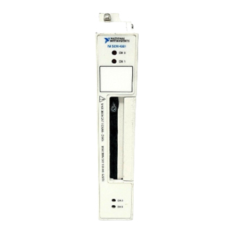
National Instruments SCXI-1321 Installation Manual
Offset-null and shunt-calibration high-voltage terminal block
Hide thumbs
Also See for SCXI-1321:
- Installation manual (17 pages) ,
- Instructions for safe use (4 pages)
Table of Contents
Advertisement
Quick Links
INSTALLATION GUIDE
SCXI-1321 O
S
-C
HUNT
ALIBRATION
T
B
ERMINAL
Introduction
What You Need to Get Started
LabVIEW ™ , NI-DAQ ™, and SCXI ™ are trademarks of National Instruments Corporation. Product and company names are trademarks or trade names
of their respective companies.
321924A-01
-N
FFSET
H
IGH
LOCK
This guide describes how to install and use the SCXI-1321 offset-null
and shunt-calibration terminal block with your SCXI-1121 module.
You can only use the SCXI-1321 terminal block with SCXI-1121 revision
C and later revisions. The SCXI-1321 terminal block has a shielded board
with supports for connection to the SCXI-1121 input connector. In addition
to the 18 screw terminals, the SCXI-1321 has circuitry for offset-null
adjustment of Wheatstone bridges, and a shunt resistor for strain-gauge
shunt calibration. This terminal block was primarily designed for
bridge-type transducers such as strain gauges. The SCXI-1321 can also
easily accommodate thermocouples, RTDs, thermistors, millivolt sources,
volt sources, and current-loop receivers.
To set up and use your SCXI-1321, you will need the following items:
SCXI-1321 offset-null and shunt-calibration terminal block
SCXI-1321 Offset-Null and Shunt-Calibration Terminal Block
Installation Guide
SCXI chassis
SCXI-1121 module
No. 1 and No. 2 Phillips-head screwdrivers
1
/
in. flathead screwdrivers
8
© Copyright 1998 National Instruments Corp. All rights reserved.
ULL AND
-V
OLTAGE
August 1998
Advertisement
Table of Contents

Summary of Contents for National Instruments SCXI-1321
- Page 1 SCXI-1121 module No. 1 and No. 2 Phillips-head screwdrivers in. flathead screwdrivers LabVIEW ™ , NI-DAQ ™, and SCXI ™ are trademarks of National Instruments Corporation. Product and company names are trademarks or trade names of their respective companies. 321924A-01 ©...
-
Page 2: Safety Information
O NOT SUBSTITUTE PARTS OR MODIFY EQUIPMENT introducing additional hazards, do not install unauthorized parts or modify the device. Return the device to National Instruments for service and repair to ensure that its safety features are not compromised. When using the device with high common-mode voltages, you... -
Page 3: Temperature Sensor Output And Accuracy
SCXI device can create a shock or fire hazard or can damage any or all of the boards connected to the SCXI chassis, the host computer, and the SCXI device. National Instruments is NOT LIABLE FOR ANY resulting from incorrect signal connections. - Page 4 These sockets best fit W resistor lead size. To determine your nulling range, use the following formula (refer to Figure 1 for visual help): ± null ---------- - – -------------------------------------------------------------- - nulling range null null SCXI-1321 Installation Guide © National Instruments Corporation...
- Page 5 ±1,498 µε as given by the strain formula for a quarter-bridge strain gauge configuration: – ε ------------------------------- - GF 1 where strained voltage static unstrained voltage – ----------------------------------------------------------------------------------------------------- - © National Instruments Corporation SCXI-1321 Installation Guide...
- Page 6 Figure 1. Nulling Circuit Note stands for the completion resistors. Using the SCXI-1321 with RTDs and Thermistors When using this terminal block with RTDs or thermistor-type transducers and with the SCXI-1121 excitation set in the Current mode, you must disable the nulling circuit of the channel of interest. You can do this in two...
- Page 7 SCXI-1121, all the shunt switches close; when SCAL is cleared to 0, all the switches open. At startup or reset, all switches are open. This shunt calibration circuitry configuration places a shunting resistor in parallel with the strain gauge, as shown in Figure 2. © National Instruments Corporation SCXI-1321 Installation Guide...
- Page 8 = 3.333 V and R = 120Ω produces the following: = 0.3321 mV change Replacing the strained voltage by V in the quarter-bridge strain change equation produces an equivalent –199 µε of change. SCXI-1321 Installation Guide © National Instruments Corporation...
-
Page 9: Signal Connection
NI-DAQ or LabVIEW 2.2.1 or earlier versions, use the function or VI. If you are using register-level SCXI_Calibrate_Setup code to program the SCXI-1121 and the SCXI-1321, you must write to the SCAL register yourself. Signal Connection Note Refer to the Safety Information section before removing equipment covers or connecting or disconnecting any signal wires. - Page 10 10. Reinstall the top cover and tighten the top cover screws. 11. Connect the terminal block to the module front connector as explained in the Installation section later in this guide. Figure 3 shows the SCXI-1321 terminal block parts locator diagram. Back View Front View...
-
Page 11: Installation
Figure 4 shows the SCXI-1321 signal connections. 9 10 11 12 19 18 17 16 1 Screw Terminals 6 R4 12 R10 17 R14 2 Product Name, Assembly Number, Revision Letter, 7 R5 13 Warning Label 18 R2 and Serial Number... -
Page 12: Specifications
Cleaning the Terminal Block Clean the terminal block by brushing off light dust with a soft, nonmetallic brush. Remove other contaminants with deionized water and a stiff nonmetallic brush. The unit must be completely dry and free from contaminants before returning to service. Specifications All specifications are typical at 25°...


Need help?
Do you have a question about the SCXI-1321 and is the answer not in the manual?
Questions and answers