
Related Manuals for Eighteeth MotorSurg


Summary of Contents for Eighteeth MotorSurg
- Page 1 MotorSurg / MotorSurg(110V) Dental Implant Unit USER MANUAL Changzhou Sifary Medical Technology Co., Ltd.
- Page 2 P/N: IFU- 6735005 Version: 02 Issued: 2024.01.08 Size: 197mm X 140mm...
-
Page 3: Table Of Contents
2. Symbols used ......................9 3. Before use ......................11 Intended purpose ..................11 Contraindications ..................11 4. Assemble and disassemble the MotorSurg ..........16 Main unit connection socket ..............16 Installation and removal ................17 5. Use interface ......................28 Main unit operation panel and display .......... - Page 4 Set contra angle gear ratio ..............63 7. Operation ........................ 65 8. Cleaning, disinfection and sterilization ............67 Foreword ....................... 67 General recommendations ..............67 Autoclavable components ..............68 Disinfection components ................ 80 9. Error warnings....................... 82 10. Troubleshooting ....................83 11.
-
Page 5: Scope Of Motorsurg
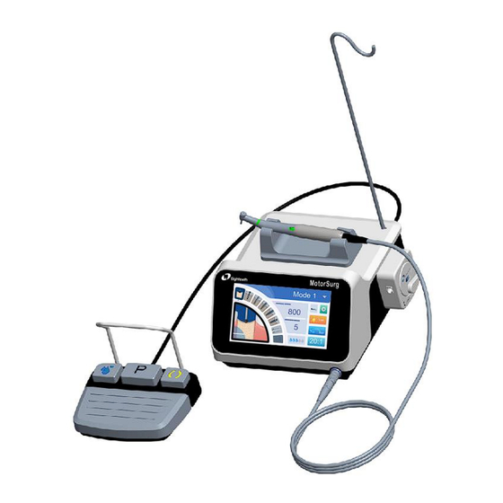
1 Scope of MotorSurg 1. Scope of MotorSurg 1.1 Parts identification ① Main unit; ②Foot pedal with cord; ③Contra angle holder; ④Bottle holder; ⑤Motor with cord; ⑥Power cord; ⑦Protection plug; ⑧USB flash drive; ⑨Irrigation tube; ⑩Fuse; O-ring (protection plug); O-ring (motor);... -
Page 6: Components
Scope of MotorSurg 1.2 Components Main unit (220V/110V) (1pc) Foot pedal with cord (1pc) Motor with cord (1pc) Power cord (1pc) Contra angle holder (1pc) Irrigation tube (5pcs) Protection plug (1pc) Fuse (2pcs) O-ring (motor) (2 pcs) O-ring (protection plug) -
Page 7: Power Cord
Scope of MotorSurg Dental Contra-angle Handpiece Spray Nozzle (1pc) (1pc) Nozzle Holder (1pc) Needle (1pc) Internal irrigation nozzle (1pc) Y connector (1pc) Screw driver(1pc) 1.3 Power cord Following AC power cords are available. Please choose the according AC power cord that meets the local standard. -
Page 8: Essential Performance
Scope of MotorSurg European standard Power cord (6615006) American standard Power cord (6615031) British standard Power cord (6615032) Australian standard Power cord (6615033) Argentine standard Power cord (6416011) 1.4 Essential performance MotorSurg has no essential performance 8 / 99... -
Page 9: Symbols Used
2 Symbols used 2.Symbols used Warning Medical device Caution Type B applied part Serial number Catalogue number Earth (ground) Class II equipment Consult instructions for AC current Manufacturer Batch code Country of manufacture Keep dry + Date of manufacture Dispose Sterilizable in a steam accordance with... - Page 10 2 Symbols used Manufacturer's LOGO Use-by-date Sterilized using ethylene Do not desterilize S TE R ILE E O oxide Do not re-use Keep away from sunlight Do not use if package is damaged and consult 20:1L Transmission ratio 20:1 with light instructions for use Washer-disinfector for thermal disinfection...
-
Page 11: Before Use
3 Before use 3. Before use 3.1 Intended purpose The MotorSurg is intended for use in dental oral surgery by qualified personnel. 3.2 Contraindications The hemophilia patient is forbidden to use this device. The patients and doctors with heart pacemaker are forbidden to use this device. - Page 12 3 Before Use Read the following warnings before use: This device must only be used in hospital environments, clinics or dental offices by trained and qualified dental personnel. Do not use the device beyond its intended purpose. To prevent electric shock, do not unplug the AC Power Cord ...
- Page 13 RF communications equipment (including peripherals such as antenna cables and external antennas) should be used no closer than 30 cm (12 inches) to any part of the MotorSurg, including cables specified by the manufacturer. Otherwise, degradation of the performance of this device could result.
- Page 14 3 Before Use Gloves are compulsory during the whole operation. Do not bend the Irrigation Tube while the irrigation pump is operating. It may cause tube breakage. The Main Unit can be cleaned with a moist cloth. Disconnect ...
- Page 15 3 Before Use Do not use data stored in USB flash drive for diagnostic purpose. 15 / 99...
-
Page 16: Assemble And Disassemble The Motorsurg
4 Assemble and disassemble of the MotorSurg 4. Assemble and disassemble the MotorSurg Open the package. Make sure the product contains all parts listed on the packing list, if any is missed, please contact your local distributor. Place the Main unit and other components on a stable platform or special surgery cart. -
Page 17: Installation And Removal
4 Assemble and disassemble of the MotorSurg ① Motor cord connector socket ② Irrigation tube installation interface ③ Bottle holder ④ Foot pedal cord connector socket ⑤ USB flash drive socket ⑥ AC power cord connector socket ⑦ Fuse holder ⑧... - Page 18 4 Assemble and disassemble of the MotorSurg Align the ● mark on the motor cord with ● mark on the motor cord connector socket of the main unit. Push the base of motor cord plug into the motor cord connector socket until the locking joint “clicks”...
- Page 19 4 Assemble and disassemble of the MotorSurg Contra angle Motor If the O-ring on the motor connector is severely worn or damaged, please replace it with a new one to protect the motor. When assemble the O-ring, first assemble the outer O-ring, and ...
- Page 20 4 Assemble and disassemble of the MotorSurg 4.2.4 Connect the Foot pedal cord Align the mark on the Foot Pedal Cord with mark on the foot pedal cord connector socket of the main unit. Push the base of the foot pedal cord plug into the foot pedal cord connector socket until the locking joint into place, when you hear a “click”...
- Page 21 4 Assemble and disassemble of the MotorSurg 4.2.6 Install the Bottle holder Align and insert the Bottle holder into the location hole on the top of the main unit. Align 4.2.7 Install the irrigation tube Open the pump by setting the pump locking handle at the “open”...
- Page 22 4 Assemble and disassemble of the MotorSurg backside of the main unit. Put the tube into the tube guide position, then close the pump by setting the pump locking handle at the “close” position. Tube guide water flow direction Connect to the...
- Page 23 4 Assemble and disassemble of the MotorSurg Insert the irrigation tube needle into the bottle cap. Connect the irrigation tube to the contra angle water inlet. Open the tube cap to supply air into the bottle. Open the tube clamp.
- Page 24 4 Assemble and disassemble of the MotorSurg Before install the irrigation tube into the pump, make sure that the water flow direction is correct. If the direction is wrong, the coolant solution can’t reach contra angle. Please check if the cooling water is normal after connecting ...
- Page 25 4 Assemble and disassemble of the MotorSurg Revolve Insert P u s h Removal: Depress the push button and remove the bur after the internal chunk is fully released. Refer to the figure below. If the O-ring on the motor connector is severely worn or ...
- Page 26 4 Assemble and disassemble of the MotorSurg Do not touch the rotating bur. Do not press the back button during treatment. Removing the bur after treatment immediately, to avoid injury or infection during placement. Never using a needle with a worn rod.
- Page 27 4 Assemble and disassemble of the MotorSurg Then install the fuse into the fuse box, and finally push fuse box into the main unit. 27 / 99...
-
Page 28: Use Interface
5 Use interface 5.Use interface 5.1 Main unit operation panel and display ① Program steps: Display the selected program step. Up to 8 program steps can be set for each program mode. ② Speed: Display and set the output rotation speed of the contra angle. - Page 29 5 Use interface ⑤ Program selecting: Select the program mode by touching this symbol. ⑥ The activity of the current program step: Display the operator activity of the current program step. A total of 9 program activities can be set (Position, Pilot drilling, Template drilling, Tapping, Implanting, Capping, Free use, Rinsing, Finished).
-
Page 30: Foot Pedal
5 Use interface 5.2 Foot pedal ① Motor starting button: User can start the motor by pressing the button, and stop the motor by releasing the button on the foot pedal. ② Pump button: User can set the coolant solution flow by pressing the pump button on the foot pedal. - Page 31 5 Use interface Program mode Such as Mode 1-Mode 8 Position, Pilot drilling, Template drilling, Activity Tapping, Implanting, Capping, Rinsing, Free use, Finished 31 / 99...
-
Page 32: Setting
Setting 6. Setting 6.1 System setting Touch the system setting symbol on the main interface. It will display the system setting window as follows: Setting Volume Foot Pedal Mode LCD Light Real-time Torque LUX Fade-out Time Contra Angle Electric Motor Factory Calibration Calibration... - Page 33 Setting 6.1.1 Volume setting Touch the Volume slider and slide to change the system sound. 6.1.2 LCD brightness setting Touch the LCD bright slider and slide to change the LCD brightness. 6.1.3 LUX fade-out time setting Touch the LUX slider and slide to change the LUX fade-out time. For example the setting time is 3s,it means the LED light will turn off automatically, when the motor stop working 3s later.
- Page 34 Slow start mode: The motor speed can be adjusted continuously up to the maximal level by the foot pedal. 6.1.5 Real-time torque MotorSurg can display the output real-time torque curve. It can save and export the output real-time torque curve data by the USB flash drive.
- Page 35 Setting after each motor stop (just available for Tapping, Implanting and Capping steps). Real-time Torque Torque/ N·cm When set the Real-time Torque status OFF, the main unit will not display the real-time torque curve during the operation steps. But the user can check the real-time torque by touching the the end of the operation.
- Page 36 Setting to save the data in the USB. A password input window will be open, please enter the password “1234” and confirmed. If no USB is inserted, the save button will be “ ”. 36 / 99...
- Page 37 Setting MotorSurg can save real-time torque curve data just for the present operation. If you start a new operation, it will overwrite the previous data. Please export the real-time torque curve data with USB after the operation, or you will lost the record.
- Page 38 Setting Touch “NO” to cancel the action. It will calibrate automatically till the main unit shows “calibration completed” Setting Volume Foot Pedal Mode Start Contra Angle Calibration LCD Light Real-time Torque LUX Fade-out Time 10 Contra Angle Electric Motor Factory Calibration Calibration Defaults...
- Page 39 Setting This equipment is optimized to obtain the highest calibration accuracy at a gear ratio of 20:1. For calibration use only for the 20:1 reduction contra angle. Calibration should be performed only on Sifary’s contra angle. Do not touch the main unit panel or the foot pedal during the ...
- Page 40 Setting Setting Volume Foot Pedal Mode Start Electric Motor Calibration LCD Light Real-time Torque LUX Fade-out Time 10 Contra Angle Electric Motor Factory Calibration Calibration Defaults Touch “YES” to carry out the action. Touch “NO” to cancel the action. It will calibrate automatically till the main unit shows “calibration completed”...
- Page 41 Setting Factory defaults setting can be used to re-set the main unit to its condition at the time of delivery. All program steps and device settings are re-set to their default values. Touch the symbol to restore the factory settings. In the follow window, you will be asked whether to restore to factory settings or not.
-
Page 42: Set Program Mode
” key to get back the main interface. 6.2 Set program mode 6.2.1 Editing the program mode display info MotorSurg offers 8 programs for the user. These can be assigned to various users or implant systems. Each program includes 8 motor steps. Touch the symbol, an overview of the 8 programs is displayed, user can choose any one of the 8 programs. - Page 43 Setting User can set the program display info as they like by touching the program display info area. It will open an info input window. 43 / 99...
- Page 44 Setting Touch the program info area (Mode1), it will open an editing window. In the editing window, user can input their name, the implant system or other info as they want. Dr. James-NOBEL CAPS < SPACE > When the editing is finished, touch the ”X” symbol at the top-right corner of the window, to close the editing window.
- Page 45 Setting A maximum of 16 characters can be entered for program info editing 6.2.2 Program step setting 6.2.2.1 Assign program activity Under the selected program mode (Mode1), user can select the program step as they need, and assign activity for each step. 45 / 99...
- Page 46 Setting Select the program step, then touch the activity of current program step, this will open a “choose the activity” window. It shows all activities. User can select the expected activity for the step. Then touch the “ ” symbol to close the window. 46 / 99...
- Page 47 Setting 6.2.2.2 Limiting the program steps The number of program steps can be limited. Program steps not needed can be deleted from the display. User can set the limiting of program step by selecting the program step and assign the activity “Finished”.
- Page 48 Setting 6.2.3 Exemplary program step sequences Example 1: Factory default setting (Mode1-Mode8) step Activity Symbol Position Pilot drilling Template drilling Tapping Implanting Capping 48 / 99...
- Page 49 Setting Free use Rinsing Example 2: step Activity Symbol Position Pilot drilling Template drilling Rinsing 49 / 99...
- Page 50 Setting Implanting Capping Finished Example 3: step Activity Symbol Position Pilot drilling Template drilling 50 / 99...
- Page 51 Setting Rinsing Finished 6.2.4 Select the program step User can select the program step by touching the program steps on the main operation panel, or by pressing the program step button (P) at the middle of foot pedal. Short press to select the next program step, and long press for 2s to return to the previous step.
-
Page 52: Set Activities Parameters
Setting 6.3 Set activities parameters MotorSurg is based on program steps and associated activities, and can be operated intuitively through the user interface. The program step is shown on the display as number ①, and the corresponding activity of the current step is shown on the display as number ②. - Page 53 Setting activity by selecting the corresponding activity. Visualizing the activity is an easy means for checking if the activity set on the device is the same as the current treatment step. Maloperation can thus be largely prevented. Default values have been set at the factory for the parameters: speed, torque, gear ratio, and coolant flow rate for every activity according to the clinical application.
- Page 54 Setting 200- 5-80 16:1 2000 200- 5-80 Pilot 20:1 drilling 2000 200- 5-80 27:1 1200 200- 5-80 16:1 2000 200- 5-80 Template 20:1 drilling 2000 200- 5-80 27:1 1200 5-80 16:1 15-50 Tapping 5-80 20:1 10-50 5-80 27:1 10-50 54 / 99...
- Page 55 Setting 5-80 16:1 15-50 Implanting 5-80 20:1 10-50 5-80 27:1 10-50 5-15 16:1 15-50 Capping 5-15 20:1 10-50 5-15 27:1 10-50 200- 0.2-5.4 40000 5-80 16:1 2000 Free use 5-80 20:1 2000 5-80 27:1 1200 Rinsing Finished A treatment sequence can consist of 1 to 8 program steps and/or activities.
- Page 56 Setting through any arrangement of the activities. During the sequence, the foot pedal is used for navigation so that the device does not have to be touched again during the operation. Changed values are saved automatically and are available for the next use.
- Page 57 Setting Implanti 20:1 Capping 20:1 Free use 20:1 Rinsing Finished The listed indications are only examples. In order to prevent risks, it is essential to comply with the manufacturer’s recommendations concerning implants, contra angles, and tools. 57 / 99...
-
Page 58: Setting The Output Speed
Setting 6.4 Setting the output speed Touch the speed display area “800”. Touch the slider and slide to expected value for quick setting, or you can touch the “-” or “+” for an accurate speed. When the speed selected, touch the speed display area again to get back. 58 / 99... -
Page 59: Setting The Output Torque
Setting 6.5 Setting the output torque Touch the torque display area “5”. Touch the slider and slide to expected value for quick setting, or you can touch the “-” or “+” for an accurate Torque. 59 / 99... -
Page 60: Set The Coolant Flow
Setting When the torque is selected, touch the torque display area again to get back. 6.6 Set the coolant flow 60 / 99... - Page 61 Setting Touch the coolant flow display to set the coolant flow, or can be set by short pressing the pump button on the left of the foot pedal. The coolant flow can be set to 5 levels and off. Off. Level 1=approx.
-
Page 62: Set Led Light Brightness
Setting rinsing mode by short pressing the pump button on the foot pedal or touch the “ ” symbol on the operation panel Setting Volume Foot Pedal Rinsing mode Mode Press pedal to star Exit with pump button LCD Light Real-time Torque LUX Fade-out Time 10... -
Page 63: Set Motor Rotation Direction
Touch the direction symbol on the main interface to change the motor rotation direction, or press the rotation direction button on the right of foot pedal. When the rotating direction is reversing, MotorSurg will produce a “di di” sound, to avoid maloperation. 6.9 Set contra angle gear ratio Touch the gear ratio symbol to set the value as expected. - Page 64 Setting For “Free use” activity, there are 4 gear ratios to be selected: 1:1, 16:1, 20:1, 27:1. For other activities, there are 3 gear ratios to be selected: 16:1, 20:1, 27:1. All changed values are saved automatically and are available for the next use.
-
Page 65: Operation
Operation 7. Operation 1. Install the product correctly according to the product installation steps; 2. Turn on the power switch on the back of the main unit and enter the standby state; 3. Under the standby state, select a program mode and set the parameters;... - Page 66 Operation otherwise the output torque is not equal to the set, it will cause treatment failure or harm to the patient. Check the contra angle to make sure that the coolant solution flow functions normally. If the coolant solution flow function is abnormal, stop using it.
-
Page 67: Cleaning, Disinfection And Sterilization
Clean, disinfection and sterilization 8. Cleaning, disinfection and sterilization 8.1 Foreword For hygiene and sanitary safety purpose, the components (motor with cord, contra angle holder, protection plug, Dental contra- angle handpiece, Y connector, nozzle holder, internal irrigation nozzle) must be cleaned, disinfected and sterilized before each usage to prevent any contamination. -
Page 68: Autoclavable Components
Cleaning, disinfection and sterilization ● For your own safety, please wear personal protective equipment (gloves, safety glasses, etc.). ● Use only a disinfecting solution which is approved for its efficacy (VAH/DGHM-listing, CE marking, and FDA approval) and in accordance with the IFU of the disinfecting solution manufacturer. ●... - Page 69 Cleaning, disinfection and sterilization Reprocessing instructions Preparation at the point of use: Disconnect the motor cord from the main unit. Refer to "Chapter 4.2.2 - Connect the motor cord" of this manual for disassembly instructions. Remove gross contaminations, from the surface of motor with cord, contra angle holder, protection plug, Dental contra-angle handpiece, Y connector, nozzle holder, internal irrigation nozzle with a cloth, which is dipped in cold water (<40°...
- Page 70 Cleaning, disinfection and sterilization Do not rinse the motor with water, to prevent water from entering the motor. Before first use and after each use, make sure to sterilize the above mentioned parts. Transportation: Safe storage and transportation to the reprocessing area to avoid any damage and contaminate on to the environment.
- Page 71 Cleaning, disinfection and sterilization Pull out the head assembly and remove the guide nozzle. The guide nozzle should be carefully stored after removal to avoid being lost. Revolve the driving shaft counterclockwise and remove it from the head. Dredge waterways: Wash the disassembled parts and accessories with neutral or mild alkaline cleaning liquid (<40°C) for at least 15s until there is no stain on the surface, and then rinse the cleaning liquid with...
- Page 72 Cleaning, disinfection and sterilization Installation steps: Assemble the bur to the head (refer to chapter 4.3), rotate the drive shaft clockwise. Please revolve the bur when the shaft is screwed to the bottom, to prevent the gear from sticking. Insert the guide nozzle to the handle, then insert the shaft into handle.
- Page 73 Cleaning, disinfection and sterilization Twist the screw clockwise, and install the screw cover, please be sure the cover direction is right. Cleaning: 1. Manual cleaning for motor with cord, protection plug and contra angle holder To prevent water from entering the motor, manual cleaning is recommended.
- Page 74 Cleaning, disinfection and sterilization which is dipped in Ethanol (70-80 vol% Ethanol), at least 2 minutes each time. 2. Auto cleaning for dental contra-angle handpiece, Y connector, nozzle holder, internal irrigation nozzle: Carefully put the components into the washer-disinfector on a tray and set the parameters as follows, then start the program: 4 min pre-washing with cold water (<40°C);...
- Page 75 Cleaning, disinfection and sterilization 1. Manual disinfection for motor with cord, protection plug and contra angle holder: Wipe the surface of the motor (including protection plug and contra angle holder) for 5 times, with a soft cloth which is dipped in Ethanol (70-80 vol% Ethanol), at least 2 minutes each time.
- Page 76 Cleaning, disinfection and sterilization Drying of outside of instrument through drying cycle of washer/disinfector. If needed, additional manual drying can be performed through lint free towel. Insufflat cavities of instruments by using sterile compressed air. Protection plug installation: To prevent the steam from entering the motor, please insert the protection plug into motor connector before sterilization.
- Page 77 Cleaning, disinfection and sterilization Before packaging and autoclaving, the dental contra-angle handpiece must be lubricated according to manufacturer’s instruction. Packaging: Pack the instruments in an appropriate packaging material for sterilization. Check the validity period of pouch given by the ...
- Page 78 Cleaning, disinfection and sterilization ISO 17665) under consideration of the respective country requirements. Minimum requirements: 3 min at 134 °C (in EU: 5 min at 134 °C) Maximum sterilization temperature: 137°C Drying time: at least 8min Use only approved autoclave devices according to EN ...
- Page 79 Cleaning, disinfection and sterilization Check the packaging and the Motor and Contra angle holder before use (packaging integrity, no humidity and validity period). The instructions provided above have been validated by the manufacturer of the medical device as being capable of preparing a medical device for use.
-
Page 80: Disinfection Components
Cleaning, disinfection and sterilization 8.4 Disinfection components Disinfection components Main unit AC Power cord Foot pedal with cord (1pc) Bottle holder Wipe all the surfaces with a damp cloth lightly moistened until all the surfaces are visually clean, then wipe all the surfaces with a cloth lightly moistened with Ethanol for Disinfection (Ethanol 70 to 80 vol%) at least 2min, repeat for 5 times. - Page 81 Cleaning, disinfection and sterilization 81 / 99...
-
Page 82: Error Warnings
Error warnings 9. Error warnings Error warnings Reasons Solutions The USB Flash Real-time Torque Drive Insert Torque/ N·cm inserted, when Flash ERROR! Please insert USB Flash Drive save real- Drive time torque The motor is not Connect the ERROR!0x01 connected motor Data storage Contact the... -
Page 83: Troubleshooting
Troubleshooting 10. Troubleshooting When trouble is found, check the following points before contacting your distributor. If none of these are applicable or the trouble is not remedied even after actions have been taken, the product may have failed. Contact your distributor. Problem Cause Solution... - Page 84 Troubleshooting Tube clamp is closed. Open the tube clamp. Pump locking is not Check and close the closed. pump locking. Check the tube and Tube is kinked. remove the kink, if any. Coolant solution bottle Open the tube cap. ventilated. Check to make sure The motor cord is not the motor cord is...
- Page 85 Replace the LED. hanpiece Unsuitable contra Use a suitable contra angle is used. angle. Unauthorized modification of the MotorSurg may cause the following hazards: The motor can’t reverse. The main unit can’t control the motor. Circuit board is damaged.
-
Page 86: Technical Data
Technical data 11. Technical data Changzhou Sifary Medical Manufacturer Technology Co., Ltd. Model MotorSurg MotorSurg(110V) ~220-240V Power supply ~100-120V 50/60Hz 50/60Hz Input power 110VA 110VA Fuse T1.6AL 250V T3.15AL 250V Max. Coolant flow 130mL/min(test with no handpiece) Speed range 200-40000r/min, ±10% Torque range 5-80 N·cm... - Page 87 Technical data Ordinary equipment (IPX0); Ingress protecting rating Foot pedal (IPX6) Intermittent operation: ON 2 min. / OFF Operating mode 8 min. Use: in enclosed spaces Ambient temperature: 5°C ~ 40 °C Operation conditions Relative humidity: 30%~ 75% Atmospheric pressure: 70kpa ~106kpa Ambient temperature: -20 °C ~ +55 °C Transport and storage Relative humidity: 20% ~ 80 %...
-
Page 88: Emc Tables
Guidance and manufacturer’s declaration - electromagnetic emissions The MotorSurg is intended for use in the electromagnetic environment specified below. The customer or the user of the MotorSurg should assure that it is used in such an environment. Complian Electromagnetic Emissions test... - Page 89 Guidance and manufacturer’s declaration – electromagnetic immunity The MotorSurg is intended for use in the electromagnetic environment specified below. The customer or the user of the MotorSurg should assure that it is used in such an environment. Immunity IEC 60601 Compliance...
- Page 90 EMC tables hospital environment. Surge IEC Line to line: Line to line: Mains power 61000-4-5 ±0.5kV, ±0.5kV, quality should ±1kV , ±1kV , be that of a Line to Line to typical ground: ground: commercial ±0.5kV, ±0.5kV, hospital ±1kV , ±1kV , environment.
- Page 91 EMC tables sine phase at sine phase at 0° 0° recommended that devices be Voltage 0% UT; 0% UT; powered form interruptions 250/300 cycle 250/300 cycle IEC 61000- uninterruptible 4-11 power supply or a battery Rated 30 A/m 30 A/m Power freque- Power...
- Page 92 EMC tables The MotorSurg is intended for use in the electromagnetic environment specified below. The customer or the user of the MotorSurg should assure that it is used in such an environment. Electromagnetic 60601 Compliance Immunity test environment - test...
- Page 93 The MotorSurg has been tested with the immunity test level in the below table and meet the related requirements of IEC 60601-1-2:2020. The customer and/or user should help keep a minimum distance 30cm between RF wireless communications equipment and the MotorSurg.
- Page 94 Guidance and manufacturer’s declaration –Proximity magnetic fields The MotorSurg is intended for use in the electromagnetic environment specified below. The customer or the user of the MotorSurg should assure that it is used in such an environment. 94 / 99...
- Page 95 Motor tail cable Foot pedal cable Use of accessories and cables other than those specified or provided by the manufacturer of MotorSurg could result in increased electromagnetic emissions or decreased electromagnetic immunity of MotorSurg and result in improper operation.
- Page 96 EMC tables Use of MotorSurg adjacent to or stacked with other equipment should be avoided because it could result in improper operation. If such use is necessary, MotorSurg and the other equipment should be observed to verify that they are operating normally.
-
Page 97: Warranty
12 months starting from the day of delivery to the customer. 2) MotorSurg should be repaired by the Customer Service Department of Changzhou Sifary Medical Technology Co., Ltd. or maintenance service partners authorized by Changzhou Sifary Medical Technology Co., Ltd. -
Page 98: Statement
Statement 14. Statement Shelf Life The shelf life of MotorSurg series products is 5 years. To ensure continued safe use of MotorSurg. It is recommended that the equipment (motor and main unit) be checked and repaired at the dealer once a year. - Page 99 Statement Any serious incident should be reported to manufacturer and competent authority. Changzhou Sifary Medical Technology Co., Ltd. Add: No. 99, Qingyang Road, Xuejia County, Xinbei District, 213000 Changzhou, Jiangsu, China Tel: +86-0519-85962691 Fax: +86-0519-85962691 Email: Info@sifary.com Web: www.sifary.com All rights reserved. 99 / 99...
Need help?
Do you have a question about the MotorSurg and is the answer not in the manual?
Questions and answers