Table of Contents
Advertisement
Advertisement
Table of Contents

Related Manuals for Eighteeth E-connect S


Summary of Contents for Eighteeth E-connect S
- Page 1 0197 E-connect...
- Page 2 USER MANUAL Page 2 / 59...
-
Page 3: Table Of Contents
Content 1. Scope of E-connect S ........................5 Parts Identification ......................5 Components and Accessories ..................6 Options (sold separately) ....................6 2. Symbols used in the User Manual ....................8 3. Before Use ............................10 Intended Use ........................10 Contraindications ...................... - Page 4 8. Maintenance ............................45 9. Error Warning ........................... 48 10. Troubleshooting ..........................49 11. Technical Data ..........................52 12. EMC Tables ............................53 13. Statement ............................58 Page 4 / 59...
-
Page 5: Scope Of E-Connect S
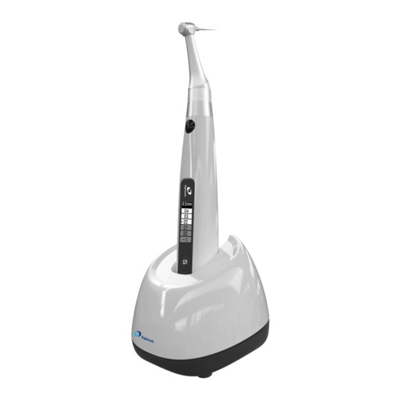
1. Scope of E-connect S 1.1 Parts Identification 1.Charge Base 2.Handpiece 3.Contra Angle 4.Insulating Sleeve 5.File Clip (2 pcs) 6.Lip Hook (2 pcs) 7.Measuring Wire 8.Adapter Page 5 / 59... -
Page 6: Components And Accessories
1.2 Components and Accessories Motor Handpiece (1pcs) Charge Base (1pcs) Contra Angle (1pcs) Part No. 6051032 Part No. 6051033 Part No. 6041003 Adapter (1pcs) Measuring Wire (1pcs) Lip Hook (2pcs) Part No. 6016001 Part No. 6015011 Part No. 6072002 Insulating Sleeve (1pcs) File clip (2pcs) Spray Nozzle (1pcs) Part No. - Page 7 Page 7 / 59...
-
Page 8: Symbols Used In The User Manual
2. Symbols used in the User Manual If the instructions are not followed properly, operation may WARNING lead to hazards for the product or the user/patient. Additional information, explanation of operation and NOTE performance. Serial number Catalogue number Manufacturer Date of manufacture Safety class II device Type BF applied part CE marking... - Page 9 Manufacturer’s LOGO Page 9 / 59...
-
Page 10: Before Use
3. Before Use 3.1 Intended Use E-connect S is exclusively designed for dentists for use with dental root canal instruments in continuous rotation and in reciprocating movement with integrated apex locator. This device must only be used in hospital environments, clinics or dental offices by qualified dental personnel. - Page 11 Page 11 / 59...
-
Page 12: Installing The E-Connect S
4. Installing the E-connect S Page 12 / 59... -
Page 13: Installation Of The Contra Angle
4.1 Installation of the contra angle Make sure 4 pins on contra angle You can also use disposable sleeve alignment the slots of handpiece, plug (sold separately) instead of insulating them together until it “click” securely into sleeve place. NOTE Without the insulating sleeve, when performing the apex measurement with The contra angle can be 340 degrees... -
Page 14: Connecting Measuring Wire
recommend using an insulating sleeve. Push Button WARNING Inspect the file head before inserting the file. Do not use the damaged file head. Single apex function only Make sure the motor is stopped when inserting and removing files. Be careful when inserting and removing files to avoid injury to fingers. - Page 15 Power LED Insert lip hook into white slot, insert file clip into black slot. NOTE Only the original adapter could be NOTE used. It’s not necessary to connect file clip during motor combine apex function, only during single apex function. If only need a base to put the device on Put the handpiece all the way into the dentist element of dental chair ( without...
- Page 16 in the right direction, otherwise the handpiece will not be recharged. Page 16 / 59...
-
Page 17: Use Interface
5.Use Interface Page 17 / 59... -
Page 18: Panel Key
5.1 Panel key Turn Power On Press ● more than 0.5 seconds to turn on the instrument Memory Change Press < > during standby state Operation mode Change Press once during standby state, press < > to change, then press ● or wait 5 seconds to confirm Parameter Adjustment Press... -
Page 19: Screen Display
⑤ > Increase key Advanced setting During power off state, holding down press then press ● to entry advanced setting, Press till target setting, press < > to adjust, then press ● to confirm 5.2 Screen display Standby interface ① Memory mode number ②... - Page 20 ① The set maximum torque ② Real time torque R ef er ence poi nt ③ Torque display scale ④ The preset speed Reference point interface ① Flash bar of apical reverse position ② Apex (Major/Anatomic apical foramen) ③ 0.5mm meter reading (Very near Minor/Physiological apical foramen) ④...
- Page 21 Canal measurement standby interface ① Memory mode number M0 is apex stand-alone memory ② Electronic apex locator ③ Apex flash bar Canal measurement start interface ① Indication number The number has no represent of actual length, only for indication ② Canal length indicator bar ③...
- Page 22 Page 22 / 59...
-
Page 23: Terms And Definition
5.3 Terms and definition Forward ( Clockwise rotation ) Reverse ( Counter clockwise rotation ) Be applied to special file, inject calcium hydroxide and other solutions Reciprocation Be applied to reciprocating file, path file and rotary file protection by setting some special angle Adaptive torque control Up to setting torque, the motor will move with reciprocating mode;... - Page 24 Operation Mode Such as FWD, REV, REC and ATC Page 24 / 59...
-
Page 25: Setting
6.Setting 6.1 Selecting memory E-connect S has 11 memory programs, press < > to change during standby state, the memory number (○, ) will change according. r pm M1-M10 is standard working memory for canal 3 .0 N cm shaping, every memory has its own speed (○,... - Page 26 E-connect S has 4 operation modes: FWD, REV, REC and ATC (See chapter 5.3 Terms and definition to get the explanations of these modes). O per at i on M ode NOTE When choice REV mode, a slow beep alarm sound appears after starting the motor, used for indicating counter clockwise rotation happening.
- Page 27 Be careful to use this function, very professional skill is needed, otherwise has risk of file broken. E-connect S integrated apex locator, if the lip hook is connecting with patient’s lip, when the endo file entering root canal, motor will start automatically.
-
Page 28: Preset Programs
During combined length determination, normally apical reverse must active before reaching major apical foramen, Press < > to set apical R ef er ence poi nt reverse position by change the flash bar (○, ), the motor will reverse while reaching the flash bar every time. - Page 29 If you selecting “OneCurve” (○, ), the operation mode (○, ), speed (○, ) and torque limit (○, ) will change according to the file system default setting. NOTE Protaper , GATES , Pro.Glider , and ○, ○, ○, Wave one is a registered trademark of ○, Dentsply.
-
Page 30: Advanced Setting
During power off state, holding down press then press ● to entry advanced setting, the version number software will appear on the display screen. E-connect S can update software very easy without tools and software. Contact your distributor to update if Ver si ons necessary. - Page 31 Press again, the “Auto Return time” can be change, it means when setting parameters just like speed and torque, the system will back to standby interface if there is no operation in 5 seconds. A ut o R et ur n t i m e 5 Sec press <...
-
Page 32: Parameter Logic
The motor speed will increase from 120 to 1000 rpm. Calibration When the speed up to 1000 rpm, the calibration 1000 r p m successful and automatic power off. Press again, entry “Restore setting” function, press < > to select “ON”, press ● to start recovering, all the parameters be set by operator will be recovered by default factory setting (See chapter 6.5 settings... - Page 33 Apical Action Reference point Angle Angle The default advanced settings are listed below, the setting can be changed as needed. Auto Power off 10Min Startup memory Auto Return time 5Sec Language English Beeper Volume Calibration Habit hand Right hand Restore settings The speeds (rpm) in different operation mode are not the same, details are listed below.
- Page 34 Speed (rpm) 120-700 700-1000 Page 34 / 59...
- Page 35 The FWD Angle (degrees) and REV Angle (degrees) in different operation mode are not the same, details are listed below. 100 120 150 160 180 The same with the front table Angle 200 230 250 260 280 300 320 340 360 370 The same with the front The same with the front table table...
-
Page 36: Operation
7.Operation 7.1 Charge Displays the present remaining amount of the battery. Less than 15% remains, please charge. NOTE If the power if less than 15%, must be recharged within 30 days, otherwise the battery will be damaged. If continue to use, the torque and speed will low LowPower than the setting value, and low power warming will Please Charge... -
Page 37: Motor Operation
5.2 Screen display). WARNING Use the E-connect S outside the oral cavity to make sure that the device is functioning properly. Change file on time to avoid file separation within the canal. File may separate Page... - Page 38 because of cyclic / torsional fatigue. Heavy force / hand pressure on endo motor while using may even cause file separation. Do not press the button to release the files while the motor is running, otherwise the file may pop out and even hurt the patient. Electromagnetic noise in surroundings environment may interfere with the device operation, do not rely on device’s automatic control completely, always pay attention to the feedback from display.
-
Page 39: Apex Operation And Not Suitable Condition
NOTE We strongly recommend check the function every time before use. Touch the lip hook with the file in the contra angle and check that all the bars on the meter on the screen light up, and the motor should be reversed continuously. - Page 40 The reference point can be adjusting when use stand-alone apex function. Press to active reference point interface during M0 standby state, R ef er ence poi nt Press < > to change reference point by change the flash bar ), a continuous beeping with ○, appear when reach the reference point.
- Page 41 the top. Unsuitable situation of root canals for Electric Measurement Cannot obtain precise measurements if the root canal conditions as below Root canal with a large apical foramen The root canal cannot be accurately measured because of the lesion or incomplete development of the apical foramen.
- Page 42 from the opening. Broken crown Build-up (e.g. cement) If the crown is broken, a segment of the gingival tissue enters the lumen, and the contact between the gingival tissue and the root file causes electrical leakage, which cannot be accurately measured. In this case, the appropriate material should be used to isolate the gingival tissue.
- Page 43 Retreatment canal which was filled with gutta-percha The gutta-percha must be completely removed to eliminate its insulation, then pass a small file all the way through the apical foramen and then put a little saline Gutta-percha in the canal, but do not let it overflow the canal opening.
- Page 44 Blocked canal The meter will not run if the canal is blocked. Opening the canal all the way to the apical construction to measure it. Blocked Extremely dry canal If the canal is extremely dry, the meter may not work until it is quite close to the apex.
-
Page 45: Maintenance
8.Maintenance Autoclavable Components Insulating Sleeve Contra Angle Lip Hook File clip WARNING Only the components above can be autoclaved. Autoclavable Procedure Cleaning Disinfection Lubrication Storage Packing Sterilization Cleaning: Clean the components with running water with a soft cloth. Disinfection: Wipe the components with a piece of gauze that has been dampened with Ethanol for Disinfection (Ethanol 70 to 80 vol%) and wrung out thoroughly. - Page 46 Minimum drying time after sterilization: 10 minutes. Storage: Keep the components in sterilization packaging in a dry and clean environment. WARNING Comply with your national guidelines, standards and requirements for cleaning, disinfection and sterilization. Be careful to avoid cross contamination when performing maintenance. Must be autoclaved after use for each.
- Page 47 Disinfection components Motor Handpiece Charge Base Adapter Handpiece Base Measuring Wire Wipe the components with a piece of gauze that has been dampened with Ethanol for Disinfection (Ethanol 70 to 80 vol%) and wrung out thoroughly. NOTE Do not use anything except Ethanol for Disinfection (Ethanol 70 to 80 vol%) Do not use too much ethanol as it’s going into machine and damage the components inside.
-
Page 48: Error Warning
9.Error Warning When setting the torque limit as R.L or during reverse processing, the Overload warning may Overload appear on the screen, it means a large load Restart Motor happened greater than the motor force. Press the Main switch to restart motor. temperature motor higher... -
Page 49: Troubleshooting
10.Troubleshooting When trouble is found, check the following points before contacting your distributor. If none of these are applicable or the trouble is not remedied even after action has been taken, the product may have failed. Contact your distributor. Ref. Problem Cause Solution... - Page 50 screen does not Contact your distributor. appear M0 mode is stand-alone apex Changing to M1-M10. locator function. The motor Clean or replace the The contra-angle is clogged doesn’t rotate. contra-angle. Motor is protected by system Check the error warning. 9 or broken.
- Page 51 Change setting if it’s not Apical action setting Stop or OFF. expected. Motor speed Change setting if it’s not Apical action setting Slow changes Down. expected. spontaneously. Motor alternates Change setting if it’s not between Operation mode setting to forward and REC or ATC.
-
Page 52: Technical Data
11.Technical Data Manufacturer Changzhou eighteeth medical technology Co.,Ltd Model E-connect S Dimensions 21.5cm x 17.5cm x 9cm (Outer box) Weight 800g Contra-angle compatible with rotary and reciprocating Contra-angle instruments, equipped with a 2.35 mm shaft conforming ISO 1797-1:2011, Type 1 Power supply Lithium ion battery: 3.7V, 1500mAh... -
Page 53: Emc Tables
Guidance and manufacturer’s declaration – electromagnetic emissions The E-connect S is intended for use in the electromagnetic environment specified below. The customer or the user of the E-connect S should assure that it is used in such an environment. Emissions test... - Page 54 Electrostatic +6 kV contact +2, 4, 6 kV Floors should be wood, discharge (ESD) contact concrete or ceramic tile. If IEC 61000-4-2 floors are covered with synthetic material, the +2, 4, 8 kV air +8 kV air relative humidity should be at least 30 %.
- Page 55 Guidance and manufacturer’s declaration – electromagnetic immunity The E-connect S is intended for use in the electromagnetic environment specified below. The customer or the user of the E-connect S should assure that it is used in such an environment. Comp...
- Page 56 RF transmitters, an electromagnetic site survey should be considered. If the measured field strength in the location in which the E-connect S is used exceeds the applicable RF compliance level above, the E-connect S should be observed to verify normal operation. If abnormal performance is observed, additional measures may be necessary, such as reorienting of relocating the E-connect S.
- Page 57 Rated maximum Separation distance according to frequency of transmitter output power of transmitter 150 kHz to 80 MHz 80 MHz to 800 MHz 800 MHz to 2.5 GHz 0.01 0.12 0.12 0.23 0.38 0.38 0.73 For transmitters rated at a maximum output power not listed above, the recommended separation distance d in meters (m) can be estimated using the equation applicable to the frequency of the transmitter, where P is the maximum output power rating of the transmitter in watts (W) according to the transmitter manufacturer.
-
Page 58: Statement
The pictures are only for reference. The final interpretation rights belong to CHANGZHOU EIGHTEETH MEDICAL TECHNOLOGY CO., LTD. The industrial design, inner structure, etc, have claimed for several patents by EIGHTEETH, any copy or fake product must take legal responsibilities. - Page 59 Changzhou Eighteeth Medcial Technology Co., Ltd Add: NO.99 Qingyang Road Xuejia Town, Xinbei District Changzhou City, 213125, Jiangsu Province, China Tel: +86-0519-85962691 Fax: +86-0519-85962691 Email: ivy@sifary.com Web: www.eighteeth.com Berwin Industy Ltd. Tel: +44 0208 492 6388 Fax: +44 0208 492 0196 Add: 419, Harborne Road, Edgbaston, Birmingham, B15 3LB.
Need help?
Do you have a question about the E-connect S and is the answer not in the manual?
Questions and answers