Table of Contents
Advertisement
Advertisement
Table of Contents

Related Manuals for Eighteeth UltraMint


Summary of Contents for Eighteeth UltraMint
- Page 1 Model: UltraMint ULTRASONIC SCALER USER MANUAL...
-
Page 3: Table Of Contents
Catalog 1. Overview..........................4 1.1 Content............................4 1.2 Packing list and coding....................... 5 2. Symbol instruction......................6 3. Foreword..........................8 3.1 Scope of application........................8 3.2 Contraindications........................8 4. Installation.......................... 9 4.1 Front view...........................9 4.2 Back view............................ 9 4.3 Installation steps........................10 4.4 Handpiece installation and removal..................12 4.5 Tip installation and removal..................... -
Page 4: Overview
Overview 1. Overview 1.1 Content 1. Main Unit 2. Power Adapter 3. Foot Pedal 4. Handpiece Support 5. Handpiece 6. Tip 7. External Water Supply Hose 8. Wrench Page 4 / 35... -
Page 5: Packing List And Coding
Overview 1.2 Packing list and coding Main unit (1 pc) Power adapter (1pc) Foot pedal (1 pc) 6651026 6651030 6651027 Handpiece support (1 pc) External water supply hose Handpiece (1 pc) 6604008 (1 pc) Store in the Instrument Box 6641006 6651005 Wrench (1 pc) Tips (6 pcs) -
Page 6: Symbol Instruction
Symbol instruction 2. Symbol instruction If the instructions are not followed properly, operation may WARNING lead to hazards for the product or the user/patient. Additional information, explanation of operation and NOTE performance. Serial number Class II equipment Type B applied part Alternating current Dispose of in accordance with the WEEE directive Keep dry... - Page 7 Symbol instruction Date of manufacture Lot of manufacture Authorized Representative in the European Community Manufacturer’s LOGO Follow instructions for use Washer-disinfector for thermal disinfection Page 7 / 35...
-
Page 8: Foreword
Foreword 3. Foreword 3.1 Scope of application UltraMint is an ultrasonic scaler intended for use in dental applications, such as removal of dental calculus and stains, root canal treatment and periodontal therapy. This device must only be used in hospital environments, clinics or dental offices by trained and qualified dental personnel and not used in the oxygen-rich environment. -
Page 9: Installation
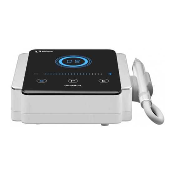
Installation 4. Installation 4.1 Front view Decrease power key Power adapter Power display window Quickly decrease/increase power key &Power indicator I nc rease power key Handpiece Foot Pedal Scaling mode Periodontal mode Wat er control knob Endodontic mode Handpiece cord 4.2 Back view Power swit ch Foot Pedal socket... -
Page 10: Installation Steps
Installation 4.3 Installation steps 4.3.1 Install the handpiece the power supply to supply power to support the main unit. WARNING Install the handpiece support to the main unit first. The power adapter must be plugged into the main unit before being plugged into the power supply. - Page 11 Installation WARNING The water source pressure should be in the range of 0.01-0.5MPa. Unscrew t he lock nut count erclockwise Lock nut Pu t the lock nut on the external water supply hose External water supply hose Connect one end of the external water supply hose to the external water hose connector Clockwise tighten the lock nut...
-
Page 12: Handpiece Installation And Removal
Installation 4.4 Handpiece installation and removal 4.4.1 Handpiece installation and Removal removal Take out lamp bead protective shield by Install and remove the handpiece as otat ing it counterclockwise shown below. Lamp bead Note that before installation, align the protective shield direction mark on the handpiece with the direction mark on the connector of handpiece cord, and then insert the... -
Page 13: Tip Installation And Removal
Installation 4.5 Tip installation and removal 4.5.1 Tip installation 4.5.2 Tip removal 1) Screw the tip to the handpiece. 1) Align the gap of the wrench with 2) Align the gap of the wrench with the tip. the tip. 2) Rotate the wrench 3) Rotate the wrench clockwise until counterclockwise until the tip it turns 90 degrees. -
Page 14: Product Function And Use
Product function and use 5. Product function and use 5.1 Operation panel instructions 5.1.1 Working mode 5.1.2 Power adjustment Power display window Decrease Increase power key power k ey Scaling mode Periodontal Endodontic mode mode Quickly decrease/increase power key This equipment can provide three &Power indicator working modes: Scaling mode, periodontal mode and endodontic... -
Page 15: Function Mode And Use
Product function and use using it. 5.2 Function mode and use Water supply function and Connect the other end of the external water supply hose to the connector that can provide water for the device. Page 15 / 35... - Page 16 Product function and use External water s upply hose Water flow adjustment Adjust the water flow through the water control knob on the handpiece cord. Water control knob Handpiece cord Page 16 / 35...
-
Page 17: Operating The Device
Product function and use 5.3 Operating the device 5.3.1 Install the device correctly sensitivity of the patient's teeth and according to the installation steps. the hardness of calculus. The operator is facing the device, and 5.3.7 Water flow adjustment: Step on the water control knob on the the foot pedal to activate the tip handpiece cord is adjusted to the... - Page 18 Product function and use 10. If use the water source without NOTE hydraulic pressure, the water 1. Keep the device clean before and surface should be 1 meter higher after use. than the head of the patient. 2. Before each use, always check that 11.
-
Page 19: Advanced Settings
Product function and use 5.4 Advanced settings 5.4.1"Cleaning" mode 5.4.2 Handpiece LED light delay adjustment It is recommended to flush the liquid The handpiece LED light will be lit circuit of the device after scaling at during the operation. The device will least once a day. -
Page 20: Cleaning, Disinfection And Sterilization
Cleaning, Disinfection and Sterilization 6. Cleaning, Disinfection and Sterilization 6.1 Foreword The parts for clinical application contamination are the outer surfaces of the handpiece, tip and wrench. For hygiene and sanitary safety purpose, these components must be cleaned, disinfected and sterilized before each usage to prevent any contamination. - Page 21 Cleaning, Disinfection and Sterilization WARNING Only the components above can be autoclaved. Before first use and after each use, sterilize the above components. Reprocessing Instructions Before cleaning, disconnect the handpiece and tips from the main unit. Disassemble the light guide and lamp beads from the handpiece.
- Page 22 Cleaning, Disinfection and Sterilization Automated Cleaning: Carefully put the components into the washer-disinfector on a tray and set the parameters as follows, then start the program: 4 min pre-washing with cold water (<40°C); emptying 5 min washing with a mild alkaline cleaner at 55°C;...
- Page 23 Cleaning, Disinfection and Sterilization Functional Visual inspection for cleanliness of the instruments and Testing, reassembling. Functional testing according Maintenance: instructions of use. If necessary, perform reprocessing process again until the instrument is visibly clean. Before packaging and autoclaving, make sure that the components have been maintained according to the manufacturer’s instruction.
- Page 24 Cleaning, Disinfection and Sterilization Waiting for cooling before touching. Storage: Storage of sterilized instruments in a dry, clean and dust free environment at modest temperatures, refer to label and instructions for use. WARNING Sterility cannot be guaranteed if packaging is open, damaged or wet.
-
Page 25: Disinfection Components
Cleaning, Disinfection and Sterilization 6.4 Disinfection components Disinfection components Main unit Power adapter Foot pedal Handpiece support External water supply hose Wipe all the surfaces with a cloth lightly moistened with Ethanol for Disinfection (Ethanol 70 to 80 vol%) at least 2min, repeat for 5 times. NOTE Do not use anything except Ethanol for Disinfection (Ethanol 70 to 80 vol%). -
Page 26: Maintenance
Maintenance 7. Maintenance When the device is not in use, the power switch should be turned off and the power plug should be unplugged. When not in use for a long time, it should be powered and watered once a month for about 5 minutes each time. Page 26 / 35... -
Page 27: Troubleshooting
Troubleshooting 8. Troubleshooting When trouble is found, check the following points before contacting your distributor. If none of these are applicable or the trouble is not remedied even after action has been taken, the product may have failed. Contact your distributor. - Page 28 Troubleshooting enough Blocked waterway Drain the waterway with dental gun The tip vibration is Working tip is loose Tighten the tip weakened Working tip is broken Replace the tip Control panel Control panel circuit Contact your local distributor malfunction board damaged or our company Water seepage at the Damaged waterproof...
-
Page 29: Technical Data
Technical Data 9. Technical Data Changzhou Sifary Medcial Technology Co. Manufacturer Model UltraMint 395mm×230mm×90mm Box dimensions Total weight 2.8kg Power supply ~220-240V 50/60Hz Main unit input ~25V 50/60Hz 1.3A Output primary tip vibration 1μm-200μm excursion Output tip vibration frequency 25kHz~42kHz Output half-excursion force 0.1N~2N... -
Page 30: Emc Tables
10. EMC Tables Guidance and manufacturer’s declaration – electromagnetic emissions The UltraMint is intended for use in the electromagnetic environment specified below. customer or the user of the UltraMint should assure that it is used in such an environment. Emissions test Compliance... - Page 31 Guidance and manufacturer’s declaration – electromagnetic immunity The UltraMint is intended for use in the electromagnetic environment specified below. The customer or the user of the UltraMint should assure that it is used in such an environment. IEC 60601 test...
- Page 32 The UltraMint has been tested with the immunity test level in the below table and meet the related requirements of IEC 60601-1-2:2014. The customer and/or user should help keep a minimum distance between RF wireless communications equipments and the UltraMint as recommended below.
- Page 33 Pedal cable Handpiece cord 2. Use of UltraMint adjacent to or stacked with other equipment should be avoided because it could result in improper operation. If such use is necessary, UltraMint and the other equipment should be observed to verify that they are operating normally...
-
Page 34: Statement
Statement 11. Statement Service Life The service life of UltraMint series products is 5 years. Maintenance MANUFACTURE will provide circuit diagrams, component part lists, descriptions, calibration instructions to assist to SERVICE PERSONNEL in parts repair. Disposal The package should be recycled. Metal parts of the device are disposed as scrap metal. - Page 35 Add: No.99, Qingyang Road, Xuejia County, Xinbei District, Changzhou City, 213000 Jiangsu, China Tel: +86-0519-85962691 Fax: +86-0519-85962691 Email: ivy@sifary.com Web: www.eighteeth.com Llins Service & Consulting GmbH Tel: +49 175 4870819 Add: Obere Seegasse 34/2, 69124, Heidelberg, Germany Email: Llins.Service@gmail.com Version: S01 IFU-6635004 Issued: 2020.7.1...
Need help?
Do you have a question about the UltraMint and is the answer not in the manual?
Questions and answers