Table of Contents
Advertisement
Advertisement
Table of Contents

Related Manuals for Eighteeth E-xtreme


Summary of Contents for Eighteeth E-xtreme
- Page 1 E-xtreme Endo Motor USER MANUAL Changzhou Sifary Medical Technology Co., Ltd.
- Page 2 Version: S02 IFU- 6035009/S02 Issued: Dec. 10 2020 Size:160mm X 92mm...
-
Page 3: Table Of Contents
Content 1. Scope of E-xtreme ..................5 1.1Parts Identification ..................5 1.2Components and Accessories ..............6 1.3 Options ......................6 2. Symbols used in the User Manual ............7 3. Before Use ......................9 3.1Intended Use ....................9 3.2Contraindications ..................9 4. - Page 4 6.5Parameter logic ..................26 7. Operation ......................28 7.1 Charge ....................... 28 7.2Motor Operation ..................30 8. Cleaning, Disinfection and Sterilization ........... 32 8.1Foreword ..................... 32 8.2General recommendations ..............32 8.3Autoclavable Components ..............33 8.4Disinfection Components ................38 9. Error warnings ....................39 10.
-
Page 5: Scope Of E-Xtreme
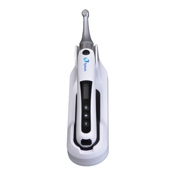
Scope of E-xtreme 1. Scope of E-xtreme 1.1 Parts Identification 1. Contra Angle 2. Motor Handpiece 3. Handpiece Base 4. Insulating Sleeve (optional) 5. Spray Nozzle 6. Adapter Note: This product does not contain root canal file Page 5 / 52... -
Page 6: Components And Accessories
Scope of E-xtreme 1.2 Components and Accessories Motor Handpiece Handpiece Base Contra Angle (1pcs) (1pcs) (1pcs) Adapter (1pcs) Spray Nozzle (1pcs) USER MANUAL (1pcs) Certificate (1pcs) Warranty card (1pcs) 1.3 Options Insulating Sleeve Page 6 / 52... -
Page 7: Symbols Used In The User Manual
2 Symbols used in the User Manual 2. Symbols used in the User Manual If the instructions are not followed properly, operation WARNING may lead to hazards for the product or the user/patient. Additional information, explanation of operation and NOTE performance. - Page 8 2 Symbols used in the User Manual 1 06kPa Atmospheric pressure limitation 7 0k P a Manufacturer's LOGO Consult instructions for use Be careful! Refer to relevant documents Washer-disinfector for thermal disinfection Page 8 / 52...
-
Page 9: Before Use
(including peripherals such as antenna cables and external antennas) should be used no closer than 30 cm (12 inches) to any part of the E-xtreme, including cables specified by the manu- facturer. Otherwise, degradation of the performance of this equipm- ent could result. - Page 10 3 Before Use 6. Gloves and a rubber dam are compulsory during treatment. 7. Never open or repair the device yourself,otherwise, void the wa- rranty. 8. If irregularities occur in the device during treatment, switch it off. Contact the agency. 9.
-
Page 11: Installing The E-Xtreme
Installing the E-xtreme 4. Installing the E-xtreme 4.1 Installation of the contra angle Make sure 4 pins on contra angle alignment the slots of handpiece, plug them together until it “clic- k” securely into place. The contra angle can be 360 deg-... -
Page 12: Charging
4 Installing the E-xtreme WARNING 1. Inspect the file head before inserting the file. Do not use the damaged file head. 2. Be careful when inserting and removing files to avoid injury to fingers. 3. Pull the file gently to make sure that the file is secure in hand- piece properly, otherwise it may pop out and hurt the patient. -
Page 13: Install The Insulation Sleeve
4 Installing the E-xtreme 4.4 Install the Insulation Sleeve Install:assemble according to the left figure Remove:pull out the cover in the opposite direction NOTE The insulating sleeve is ma- inly used for secondary isol- ation to avoid cross infec- tion. -
Page 14: Use Interface
Use Interface 5. Use Interface 5.1 Panel key Power on ● Press more than 0.5 seconds to turn on the instrument. Memory Change Press to change at st- andby mode. Operation Mode Change Press once at standby mode,p- ress to switch, then p- ●... -
Page 15: Screen Display
Use Interface 5.2 Screen display Standby interface 1 Residual battery power 2 Speed 3 Unit of speed (Revolutions Per Minute) N cm · 4 Memory mode number 5 Torque 6 Unit of torque (Newton Centimeter) 7 Operation mode Working mode interface 1 The set maximum torque 2 Real torque 3 Torque display scale... -
Page 16: Terms And Definition
Use Interface 5.3 Terms and definition Fwd/Fw Forward ( Clockwise rotation ) Rev/Rv Reverse ( Counter clockwise rotation ) Reciprocation: Be applied to reciprocating file, path file and rotary file protection by setting some special angle Memory Such as M0-M9 mode Operation Such as Fwd, Rev (set in M1-M9),Reciprocation... -
Page 17: Setting
Setting 6. Setting 6.1 Set memory mode The device has 10 memory mod- es (M0-M9) , press at standby mode , memory number (②) will change accordingly. Each memory mode includes its N cm N cm · · own speed (①),operation mode (④) and torque (③). -
Page 18: Set Parameters
Setting 6.2 Set parameters WARNING All parameters must be set according to the recommended values of root canal file manufacturer. Before starting the device for operation, make sure that all parameters are correct, otherwise there is a risk of instrument separation. Before starting the motor, check whether the operation mode (①) is correct. - Page 19 Setting NOTE In different operation modes, the values of parameters will be different according to the corresponding logic (Adjust parameters according to chapter 7.2). In M1-M9 memory mode, the s- peed can be 120rpm-650rpm. Pr- at standby mode till sp- SPEED: (①②...
- Page 20 Setting Fwd or Rev can be set in opera- tion mode of M1-M9. Press till the operation mode (①②④) is displayed, press to set, then press or wait 5 ● seconds to confirm. The left figure(③) means press DIR: ain will enter memory mode (MEM).
-
Page 21: Preset Programs
Setting 6.3 Preset programs For the convenience of the operator, so- me common root canal file systems are preset. Long press at standby mode to en- ter preset mode, the screen will display F w d as the figure shows on the left. Protaper SX&S1 40 0RPM Protaper S2... - Page 22 Setting When the preset mode is selected, the memory number(①) will be changed to the preset name, operation mode ( ② One Curve speed (③ ) and torque ( ④ ) will also be 300 RPM 2.5 N·cm automatically set. NOTE All memory modes (from M1 to M9) can be replaced by preset programs...
-
Page 23: Advanced Setting
Setting 6.4 Advanced setting Hold then press ● (for about 0.5 seconds) at off mode to enter adva- nced set mode. It will be about 1 second at SET logo an- d then enter ①“BEEP VOL”(beep vol- ume set). Press to set (②) (Mute、Low、Mid、High), then pres-... - Page 24 Setting Press again at hand habit set will enter①“Calibration”auto calibration, press to set③(ON、OFF), ● Choose“ON”and press C alib ra tion confirm and the device will auto cali- · O F F brate.The left figure ② means when choose “OFF”and press again w- ill enter restore settings (R.S).
- Page 25 Setting parameters. If necessary, please reco- rd the parameters before restoring th- e factory settings. Page 25 / 52...
-
Page 26: Parameter Logic
Setting 6.5 Parameter logic The factory default parameters of the ten memory modes are shown in the table below. The parameters can be adjusted as needed. The default advanced settings parameters are shown in the following table. The parameters can be adjusted as needed Parameter Operation REC Fwd Fwd Fwd Fwd Fwd Rev Rev Fwd Fwd... - Page 27 Setting The rotational speed (RPM) varies in different operating modes, as shown in the table below Torque (N·cm) in different operation modes, the torque value can be set differently even in the same operation mode when the speed value is set differently. See the table below for details. There are 5 fixed values of reciprocating Angle in M0 reciprocating mode, and the Angle cannot be changed., as shown in the table below.
-
Page 28: Operation
Operation 7.Operation 7.1 Charge Display the remaining power. The remaining charge is less than 15%. NOTE 1. If the battery power is less than 15%, it must be rechar- ged within 30 days, otherwise the battery will be irretrievably damaged due to low power. 2. - Page 29 Operation When charging, the charging indicator will appear on the display screen and flicker sl- owly ( ①) . When the battery is fully charged or in the state of nearly full charge, the disp- lay will stop flashing, and the charging indication is shown in the figure (②) .
-
Page 30: Motor Operation
Operation 7.2 Motor Operation In the standby mode, the root canal preparation device is started by pres- ● sing the main switch After startup, the progr- ess bar will be displayed display screen (for details of the pro- gress bar, please refer to chapter display screen interface). - Page 31 Operation NOTE 1. When there is any abnormality, please stop using the equipment. This equipment is not suitable for all types of root canals. It is recommended to use according to the instructions of root canal file. 2. The root canal file is easy to fracture at high speed. Please follow the rotation speed recommended by the manufacturer.
-
Page 32: Cleaning, Disinfection And Sterilization
Maintenance 8.Cleaning, Disinfection and Sterilization 8.1 Foreword For hygiene and sanitary safety purpose, the components (contra angle, and insulating sleeve) must be cleaned, disinfected and sterilized before each usage to prevent any contamination. This concerns the first use as well as the subsequent uses. Comply with your national guidelines, standards and requirements for cleaning, disinfection and sterilization. -
Page 33: Autoclavable Components
Reprocessing Instructions Disconnect the components (Contra Angle, Insulating Sleeve) from the handpiece. Refer to "Chapter 4-Installing the E-xtreme" of this man- ual for disassembly instructions. Remove gross contaminations from the components with code water (<40°C) immediately after use. Don’t use a fixating detergent or hot water (>40°C) as this... - Page 34 Maintenance sing area to avoid any damage and contaminate on to the environment. The devices must be reprocessed in a disassemb- led state. Preparation for WARNING Decontaminati- 1. Do not fail to take out the file before cleaning the contra angle. 2.
- Page 35 Maintenance · 5 min intermediate rinsing with warm water (>40°C); · emptying The automated cleaning processes have been validated by using 0.5% neodisher MediClean forte (Dr. Weigert). Note Acc. to EN ISO 17664 no manual reprocessing methods are required for these devices.
- Page 36 Maintenance using sterile compressed air. Functional Visual inspection cleanliness Testing, instruments and reassembling. Functional testing Maintenance according to instructions of use. If necessary, perform reprocessing process again until instrument is visibly clean. Before packaging and autoclaving, make sure that the components have been maintained acc. to manufacturer’s instruction.
- Page 37 Maintenance Minimum requirements: 3 min at 134 °C (in EU: 5 min at 134 °C) Maximum sterilization temperature: 137°C Flash sterilization is not allowed on lumen instruments! WARNING 1. Use only approved autoclave devices according to EN 13060 or EN 285. 2.
-
Page 38: Disinfection Components
Maintenance to ensure that the processing, as actually performed using equipment, materials and personnel in the processing facility, achieves the desired result. This requires verification and/or validation and routine monitoring of the process. Likewise, any deviation by the processor from the instructions provided should be properly evaluated for effectiveness and potential adverse consequences. -
Page 39: Error Warnings
Error Warnings 9.Error warnings This warning will appear on the display screen if the load exceeds Overload capacity standby R estart Motor machine during reversal. Please press the main switch key to restart the standby machine. Low Power The power is very low, charge it immediately. -
Page 40: Troubleshooting
Troubleshooting 10.Troubleshooting When trouble is found, check the following points before contacting your distributor. If none of these are applicable or the trouble is not remedied even after action has been taken, the product may have failed. Contact your distributor. Problem Cause Solution... - Page 41 Troubleshooting The handpiece is protected Check according to error damaged warning system There is a short Press the "s" key to stop motor circuit the motor and contact the cannot internal circuit dealer stop The reverse value of Check whether the torque the torque setting motor limit is too small...
-
Page 42: Technical Data
Technical Data 11.Technical Data Manufacturer Changzhou Sifary Medical Technology Co., Ltd Model E-xtreme 17.5cm x 10.9cm x 8.4cm±1cm (Outer Dimensions box) Weight 0.6kg±15% Compatible with rotary and reciprocating instruments, equipped Contra angle with 2.35mm nickel titanium root canal file conforming to ISO 1797:2017, Type 1, Files length 11-31mm. - Page 43 11 Technical Data Ambient temperature: -20 °C ~ +55 °C Transport and storage Relative humidity: 20% ~ 80 % conditions Atmospheric pressure: 70kPa ~ 106kPa Page 43 / 52...
-
Page 44: Emc Tables
12.EMC Tables Guidance and manufacturer’s declaration - electromagnetic emissions The E-xtreme is intended for use in the electromagnetic environment specified below. The customer or the user of the E-xtreme should assure that it is used in such an environment. Complian- Electromagnetic... - Page 45 11 Technical Data Electrostatic +/- 8 kV +/- 8 kV Floors should discharge contact contact be wood, (ESD) IEC concrete or 61000-4-2 +/- 2 kV, +/- 4 +/- 2 kV, +/- 4 ceramic tile. If kV, +/- 8 kV, kV, +/- 8 kV, floors are +/- 15 kV air +/- 15 kV air...
- Page 46 11 Technical Data Mains power quality should Voltage dips be that of a 0% UT; 0.5 0% UT; 0.5 typical 61000-4-11 cycle cycle commercial or at 0°, 45°, 90°, at 0°, 45°, 90°, hospital 135°, 180°, 135°, 180°, environment. If 225°, 270°, 225°, 270°, the user of...
- Page 47 11 Technical Data Guidance and manufacturer’s declaration – electromagnetic immunity The E-xtreme is intended for use in the electromagnetic environment specified below. The customer or the user of the E-xtreme should assure that it is used in such an environment. Compli- Electromagnetic...
- Page 48 When they are used in close proximity to medical equipment and/or systems, the medical equipment and/or systems’ basic safety and essential performance may be affected. The E-xtreme has been tested with the immunity test level in the below table and meet the related requirements of IEC 60601-1-2:2014.
- Page 49 217Hz WARNING 1. Use of accessories and cables other than those specified or provided by the manufacturer of E-xtreme could result in increased electromag- netic emissions or decreased electromagnetic immunity of E-xtreme and result in improper operation. Page 49 / 52...
- Page 50 Shielded or Remark Adapter Cable 2. Use of E-xtreme adjacent to or stacked with other equipment should be avoided because it could result in improper operation. If such use is necessary, E-xtreme and the other equipment should be observed to verify that they are operating normally.
-
Page 51: Statement
11 Technical Data 13.Statement Service Life The service life of E-xtreme series products is 3 years. Maintenance MANUFACTURER will provide circuit diagrams, component part lists, descriptions, calibration instructions to assist to SERVICE PERSONNEL in parts repair. Disposal The package should be recycled. Metal parts of the device are disposed as scrap metal. - Page 52 11 Technical Data Changzhou Sifary Medcial Technology Co., Ltd Add: NO.99, Qingyang Road, Xuejia County, Xinbei District, Changzhou City, 213000 Jiangsu, P.R. China Tel: +86-0519-85962691 Fax: +86-0519-85962691 Email: ivy@sifary.com Web: www.sifary.com Caretechion GmbH Tel: +49 211 3003 6618 Add: Niederrheinstr. 71, 40474 Duesseldorf, Germany Email: info@caretechion.de All rights reserved.
Need help?
Do you have a question about the E-xtreme and is the answer not in the manual?
Questions and answers