
Related Manuals for Ruijie Reyee RG-ES228GS-P


Summary of Contents for Ruijie Reyee RG-ES228GS-P
- Page 1 Ruijie Reyee RG-ES228GS-P Switch Hardware Installation and Reference Guide Document Version: V1.0 Date: 2024.02.29 Copyright © 2024 Ruijie Networks...
- Page 2 Ruijie Networks reserves the right to modify the content of the document without any notice or prompt. This manual is designed merely as a user guide. Ruijie Networks has tried its best to ensure the accuracy and reliability of the content when compiling this manual, but it does not guarantee that the content of the manual is completely free of errors or omissions, and all the information in this manual does not constitute any explicit or implicit warranties.
-
Page 3: Preface
Intended Audience This document is intended for: Network engineers Technical support and servicing engineers Network administrators Technical Support The official website of Ruijie Reyee: https://www.ruijienetworks.com/products/reyee Technical Support Website: https://www.ruijienetworks.com/support Case Portal: https://www.ruijienetworks.com/support/caseportal Community: https://community.ruijienetworks.com... -
Page 4: Table Of Contents
Contents Preface ..............................I 1 Product Overview ..........................1 1.1 Package Contents........................1 1.2 Technical Specifications ......................1 1.3 Product Appearance ........................3 1.4 Front Panel ..........................4 1.5 Back Panel ..........................5 1.6 Cooling ............................5 1.7 LEDs ............................5 2 Preparing for Installation ........................ - Page 5 2.2.7 EMI ..........................12 2.3 Tools ............................12 3 Installing the Switch ........................13 3.1 Installation Procedure ......................13 3.2 Before You Begin ........................13 3.3 Installing the RG-ES228GS-P Switch ..................13 3.3.1 Installing the Switch in a Rack ..................14 3.3.2 Installing the Switch on a Workbench ................
- Page 6 Appendix B — Mini-GBIC and SFP Modules ..................22 Appendix C — Lightning Protection ....................25 Appendix D — Cabling Recommendations ..................28 Appendix E — Machine Room Site Selection ..................33...
-
Page 7: Product Overview
RG-ES220GS-P Switch Hardware Installation and Reference Guide Product Overview Product Overview 10/100Base-T 10/100/1000Base-T 1000Base-X SFP Console Model Ports with Auto- Ports with Auto- Port Port Negotiation Negotiation 26 (Ports 1-24 RG-ES228GS-P support PoE/PoE+) Note ● An SFP port is downward compatible with 100Base-FX ports. ●... - Page 8 24 support PoE/PoE+, while ports 27 and 28 are 1000Base-X SFP ports. Optical Module See Appendix B. Copper SFP modules are not supported. The supported optical transceiver types may update without prior notification. Please contact Ruijie Networks for any updates. SFP Port 1000Base-X supported Power Supply...
-
Page 9: Product Appearance
RG-ES220GS-P Switch Hardware Installation and Reference Guide Product Overview Storage Humidity 5% RH to 95% RH, non-condensing The fan module supports adaptive fan control for speed regulation. The fan module stops when the ambient temperature is lower than 25° C or when the PoE output power is less than 185 W. -
Page 10: Front Panel
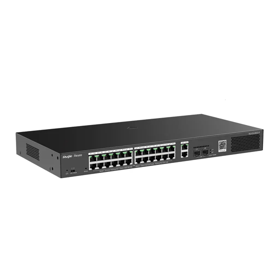
RG-ES220GS-P Switch Hardware Installation and Reference Guide Product Overview Figure 1-1 Appearance of RG-ES228GS-P Front Panel Figure 1-2 Front Panel of RG-ES228GS-P Note 1. System status LED 5. 10/100/1000BASE-T port with auto- negotiation 2. Port LED mode toggle switch 6. SFP port 3. -
Page 11: Back Panel
RG-ES220GS-P Switch Hardware Installation and Reference Guide Product Overview receiving data. LED mode switch toggled to right (Mode 2): The port LED status indicates the PoE status. Solid green means that the port is supplying power, while blinking green means that the port is in power overload state. - Page 12 RG-ES220GS-P Switch Hardware Installation and Reference Guide Product Overview Solid PoE is enabled. green Blinking The PoE port is overloaded. green The port is not connected. Solid RJ45 port Link/Ack Status The port operates at 10/100/1000 Mbps. 1-26 green Blinking The port is sending and receiving traffic at green 10/100/1000 Mbps.
-
Page 13: Preparing For Installation
RG-ES220GS-P Switch Hardware Installation and Reference Guide Preparing for Installation Preparing for Installation Safety Precautions Caution ● To avoid personal injury and device damage, carefully read the safety precautions before you install the device. ● The following safety precautions may not cover all possible dangers. 2.1.1 Safety Precautions ... -
Page 14: Electrostatic Discharge Safety
RG-ES220GS-P Switch Hardware Installation and Reference Guide Preparing for Installation supply is equal to or less than 1.5 mA, the leakage current of the system totals 30 mA. A leakage protector with 30 mA rated action current supports less than ten power supplies (that is, Action current of the leakage protector/2/Maximum leakage current of each power supply = 30/2/1.5 = 10). -
Page 15: Ventilation And Cooling
RG-ES220GS-P Switch Hardware Installation and Reference Guide Preparing for Installation 2.2.1 Ventilation and Cooling A minimum clearance of 100 mm (3.94 in.) must be maintained around the device for air circulation and ventilation. After various cables are connected, bundle the cables or place them in the patch panel to avoid blocking air inlets. -
Page 16: Anti-Interference
RG-ES220GS-P Switch Hardware Installation and Reference Guide Preparing for Installation Sulfur dioxide (SO Hydrogen sulfide Nitrogen dioxide (NO Chlorine gas (CI Note Average refers to the average value of harmful gases measured in one week. Maximum refers to the upper limit of the harmful gas measured in one week for up to 30 minutes every day. -
Page 17: Lightning Protection
RG-ES220GS-P Switch Hardware Installation and Reference Guide Preparing for Installation ● The power outlet should be installed near the device and easily accessible. ● During device installation, connect the grounding wire first and disconnect it last. ● The cross-sectional area of the protective grounding wire should be at least 0.75 mm (18 AWG). -
Page 18: Emi
RG-ES220GS-P Switch Hardware Installation and Reference Guide Preparing for Installation 2.2.7 All electromagnetic interference (EMI) sources, either from outside or inside of the device or application system, affect the device by capacitive coupling, inductive coupling, or electromagnetic waves. EMI occurs due to radiation or conduction, depending on the transmission path. When the energy, often RF energy, from a component arrives at a sensitive component through the space, the energy is known as radiated interference. -
Page 19: Installing The Switch
RG-ES220GS-P Switch Hardware Installation and Reference Guide Installing the Switch Installing the Switch Note ● Before reading chapter 3, ensure that you have read chapter 2 carefully. ● Verify that requirements described in chapter 2 have been met. Installation Procedure Before You Begin Confirm the following requirements before installation: ... -
Page 20: Installing The Switch In A Rack
RG-ES220GS-P Switch Hardware Installation and Reference Guide Installing the Switch Connect the power cords of different colors to the corresponding cable terminals. Ensure that the connector of the power cord is properly seated in the power port of the switch. After plugging the power cord into the switch, secure the power cord with power cord retention clip. -
Page 21: Installing The Switch On A Workbench
RG-ES220GS-P Switch Hardware Installation and Reference Guide Installing the Switch Figure 3-2 3.3.2 Installing the Switch on a Workbench In some cases, if a standard 19-inch rack is unavailable, the switch can be mounted on a clean workbench, as shown in Figure 3-3. The location where the switch is installed must be subject to movement restrictions. Figure 3-3 Verifying Installation Note... - Page 22 RG-ES220GS-P Switch Hardware Installation and Reference Guide Installing the Switch the power supply and interfaces are protected from lightning strikes. Verify that there is a minimum clearance of 100 mm (3.94 in.) around the switch.
-
Page 23: Debugging
RG-ES220GS-P Switch Hardware Installation and Reference Guide Debugging Debugging Setting Up the Configuration Environment 4.1.1 Connecting the Network Cable Connect one end of the Ethernet cable to the Ethernet port of the PC. Connect the other end of the Ethernet cable to any port of the switch. 4.1.2 Log In to the Web Interface for Setup Step 1: Configure your PC with an IP address in the network of 10.44.77.XXX (Range: 1-255, excluding 200). -
Page 24: Common Troubleshooting
RG-ES220GS-P Switch Hardware Installation and Reference Guide Common Troubleshooting Common Troubleshooting Troubleshooting Flowchart Common Faults 5.2.1 The SYS LED is Off After the Switch is Powered On No power is supplied to the switch, or the power cord is loose. Check whether the power socket in the machine room is normal and whether the power cable connected to the switch is loose. - Page 25 RG-ES220GS-P Switch Hardware Installation and Reference Guide Common Troubleshooting the optical transceiver with another one of the same type. Replace the optical fiber with a qualified one. Use an optical fiber with the required length. - 19 -...
-
Page 26: Appendix A - Connectors And Media
Appendix A — Connectors and Media RG-ES220GS-P Switch Hardware Installation and Reference Guide Appendix A — Connectors and Media 1000BASE-T/100BASE-TX/10BASE-T Port The 1000BASE-T/100BASE-TX/10BASE-T is a 10/100/1000 Mbps auto-negotiation port that supports auto MDI/MDIX Crossover. Compliant with IEEE 802.3ab, 1000BASE-T requires Category 5e 100-ohm UTP or STP (recommended) with a maximum distance of 100 meters (328 feet). - Page 27 Appendix A — Connectors and Media RG-ES220GS-P Switch Hardware Installation and Reference Guide Figure A-3 Twisted Pair Connections for the 100BASE-TX/10BASE-T Port Optical Fiber Connection Choose single mode or multi-mode fibers according to the module types. Figure A-4 Optical Fiber Connection...
-
Page 28: Appendix B - Mini-Gbic And Sfp Modules
Besides, the Mini-GBIC-GT modules are also supported. The following models and technical specifications of some SFP modules are listed for your reference. For details about the technical specifications, see Ruijie Hybrid Cable Installation and Reference Guide. Table B-1 Models and Specifications of 1000M Mini-GBIC (SFP) Optical Modules... - Page 29 Appendix B — Mini-GBIC and SFP Modules RG-ES220GS-P Switch Hardware Installation and Reference Guide MINI-GBIC-ZX100-SM1550 1550 GE-SFP-SX -9.5 GE-SFP-LX 1310 -9.5 SFP-MM850 -9.5 SFP-SM1310 1310 -9.5 Table B-2 1000Base-T SFP Copper Module Standard 1000Base-T SFP Module DDM (Yes/No) 1000Base-T Mini-GBIC-GT Table B-3 Cabling Specifications of SFP Modules Core Max.
- Page 30 Appendix B — Mini-GBIC and SFP Modules RG-ES220GS-P Switch Hardware Installation and Reference Guide 50/125 550 m GE-SFP-LX 9/125 10 km RJ45 Mini-GBIC-GT Ethernet Cat 5 (or higher) twisted-pair cable 100 m cable Note ● For optical modules with a cabling distance of over 40 km (24.85 miles) (including 40 km) (including 24.85 miles), install an optical attenuator to avoid overload on the optical receiver when using short-distance single-mode fibers (SMFs).
-
Page 31: Appendix C - Lightning Protection
Appendix C — Lightning Protection RG-ES220GS-P Switch Hardware Installation and Reference Guide Appendix C — Lightning Protection Installing an AC Power Arrester (Lightning Resistance Socket) When an AC power cord is introduced from outdoors and directly connected to the power port of the switch, the AC power port must be connected to an external lightning protection power strip to protect the switch against lightning strokes. - Page 32 Appendix C — Lightning Protection RG-ES220GS-P Switch Hardware Installation and Reference Guide rectify the polarity of the connection. If the indicator is still red, the arrester's PE terminal is not grounded. Installing the Ethernet Port Arrester Connect an Ethernet port arrester to the switch to prevent the damage by lightning before connecting an outdoor network cable to the switch.
- Page 33 Appendix C — Lightning Protection RG-ES220GS-P Switch Hardware Installation and Reference Guide ● The Ethernet port arrester is not delivered with the switch. Please purchase it based on actual requirements. The Ethernet port arrester user manual contains technical parameters and maintenance and installation instructions for the Ethernet port arrester.
-
Page 34: Appendix D - Cabling Recommendations
Appendix D — Cabling Recommendations RG-ES220GS-P Switch Hardware Installation and Reference Guide Appendix D — Cabling Recommendations When the switch is installed in a standard 19-inch rack, secure the cables around the cable management brackets. Adopt top cabling or bottom cabling according to the actual situation in the machine room. All cable connectors used for transit should be placed at the bottom of the cabinet rather than be exposed outside of the cabinet. - Page 35 Appendix D — Cabling Recommendations RG-ES220GS-P Switch Hardware Installation and Reference Guide Figure D-1 Binding Cables (1) Cables of different types (such as power cords, signal cables, and ground cables) should be separated in cabling and bundling. Mixed bundling is disallowed. When they are close to each other, you are advised to adopt crossover cabling.
- Page 36 Appendix D — Cabling Recommendations RG-ES220GS-P Switch Hardware Installation and Reference Guide When cables need to be bent, please bundle them up but do not tie cable them where the cables will be bent, as shown in Figure D-3. Figure D-3 Binding Cables (3) ...
- Page 37 Appendix D — Cabling Recommendations RG-ES220GS-P Switch Hardware Installation and Reference Guide Figure D-4 Cable Fastening Hard power cords should be fastened in the terminal connection area to prevent stress on terminal connection and cable. Do not use self-tapping screws to fasten terminals. ...
- Page 38 Appendix D — Cabling Recommendations RG-ES220GS-P Switch Hardware Installation and Reference Guide terminal should not be exposed outside the terminal socket when assembled.
-
Page 39: Appendix E - Machine Room Site Selection
Appendix E — Machine Room Site Selection The machine room should be at least 5 km (3.11 miles) away from heavy pollution sources, such as the smelter works, coal mine, and thermal power plant. The machine room should be at least 3.7 km (2.30 miles) away from medium pollution sources, such as the chemical factory, rubber factory, and electroplating factory.
Need help?
Do you have a question about the Reyee RG-ES228GS-P and is the answer not in the manual?
Questions and answers