Table of Contents
Advertisement
Advertisement
Table of Contents

Related Manuals for Ruijie Reyee RG-ES200 Series


Summary of Contents for Ruijie Reyee RG-ES200 Series
- Page 1 RG-ES205GC-P, RG-ES209GC-P, RG-ES218GC-P, RG-ES226GC-P, RG-ES224GC, RG-ES216GC, RG-ES205GC, RG-ES208GC, RG-ES206GC-P, RG-ES210GC-LP Series Switches Hardware Installation and Reference Guide Document Version: V1.2 Date: 2023-02-15 Copyright © 2023 Ruijie Networks...
- Page 2 Ruijie Networks reserves the right to modify the content of the document without any notice or prompt. This manual is designed merely as a user guide. Ruijie Networks has tried its best to ensure the accuracy and reliability of the content when compiling this manual, but it does not guarantee that the content of the manual is completely free of errors or omissions, and all the information in this m anual does not constitute any explicit or implicit warranties.
-
Page 3: Preface
Intended Audience This document is intended for: Network engineers Technical support and service engineers Network administrators Technical Support Official website of Ruijie Reyee: https://www.ruijienetworks.com/products/reyee Technical support website: https://www.ruijienetworks.com/support Case portal: https://caseportal.ruijienetworks.com Community: https://community.ruijienetworks.com ... -
Page 4: Table Of Contents
Contents Preface..............................I Product Overview ........................... 1 RG-ES205GC-P ....................... 1 RG-ES209GC-P ....................... 5 RG-ES218GC-P ....................... 8 RG-ES226GC-P ......................12 RG-ES224GC ........................ 16 RG-ES216GC ........................ 19 RG-ES205GC ........................ 23 RG-ES208GC ........................ 26 RG-ES206GC-P ......................29 1.10 RG-ES210GC-LP ......................33 Preparation Before Installation...................... 38 Safety Suggestions ...................... - Page 5 Troubleshooting Common Faults ..................52 Appendix A Connectors and Connection Media ................... 54 Appendix B Mini-GBIC and SPF+ Module ................... 56 Appendix C Lightning Protection......................59 Appendix D Cabling Recommendations in Installation ................. 62 Appendix E Site Selection ........................66...
-
Page 6: Product Overview
Hardware Installation and Reference Guide Product Overview 1 Product Overview The RG-ES200 series switches include the following models. Table 1-1 RG-ES200 Series Switches 10/100Base-T Auto- 10/100/1000Base-T Model sensing Ethernet Port Auto-sensing Ethernet 1000Base-X SFP Port Console Port Port (ports 1–4 support PoE/PoE+)... - Page 7 Hardware Installation and Reference Guide Product Overview Rated voltage range: 100 V to 240 V Maximum voltage range: 90 V to 264 V Frequency: 50/60 Hz Rated current: 1.5 A Adapter output Rated voltage range: 54 V DC Rated current range: 1.11 A Not supported PoE/PoE+ support Ports 1 to 4 support PoE/PoE+ with the maximum power output of 30 W per port.
- Page 8 Hardware Installation and Reference Guide Product Overview Front Panel Figure 1-2 Front Panel of the RG-ES205GC-P Note: 1. System status LED 4. Electrical port status LED 2. Port mode switchover button 5. Electrical port status LED 3. 10/100/1000Base-T auto-sensing Ethernet port 6.
- Page 9 Hardware Installation and Reference Guide Product Overview When the button is turned to the right position (Mode 2), the LED indicates the PoE status of ports. When the LED is solid green, the PoE-supported ports are supplying power. When the LED blinks green, the power of the ports is overloaded.
-
Page 10: Rg-Es209Gc-P
Hardware Installation and Reference Guide Product Overview Panel Identification State Meaning The PoE power exceeds the power of the entire device (54 W). The newly connected PD cannot Blinking green be powered up due to insufficient power. The System status switching function is operational. - Page 11 Hardware Installation and Reference Guide Product Overview The overall maximum output power of PoE/PoE+ is 120 W. PoE Mode Mode A (data pairs 1-2 and 3-6) Power Less than 10 W with no PoE load Consumption Less than 120 W with PoE full load Operating 0°...
- Page 12 Hardware Installation and Reference Guide Product Overview Figure 1–5 Front Panel of the RG-ES209GC-P 1. System status LED 5. Electrical port status LED Note: 2. Port mode switchover button 6. 10/100/1000Base-T auto-sensing Ethernet port 3. Electrical port status LED 4. 10/100/1000Base-T auto-sensing Ethernet port 7.
-
Page 13: Rg-Es218Gc-P
Hardware Installation and Reference Guide Product Overview The switch restarts after the reset button is pressed for less than 2 seconds. The switch restores the default factory settings after the reset button is pressed for more than 5 seconds (until the status LED blinks). - Page 14 Hardware Installation and Reference Guide Product Overview Frequency: 50/60 Hz Rated current: 6A Power cord: 10 A Not supported PoE/PoE+ support Ports 1-16 are PoE/PoE+-capable with the maximum power output of 30W per port. The overall maximum output power of PoE/PoE+ is 240 W. PoE Mode Mode A (data pairs 1-2 and 3-6) Power...
- Page 15 Hardware Installation and Reference Guide Product Overview Front Panel Figure 1–8 Front Panel of the RG-ES218GC-P Note: 1. Power status LED 5. 10/100/1000Base-T auto-sensing Ethernet port 2. Port mode switchover button 6. SFP port 3. System reset button 7. SFP port status LED 4.
- Page 16 Hardware Installation and Reference Guide Product Overview The switch restores the default factory settings after the reset button is pressed for more than 5 seconds (until the status LED blinks). Back Panel Figure 1–9 Back Panel of the RG-ES218GC-P Note: 1.
-
Page 17: Rg-Es226Gc-P
Hardware Installation and Reference Guide Product Overview Panel Identification State Meaning PoE is not enabled. RJ-45 port 1–16 Solid green PoE is enabled. The port is operational. status LED Blinking green PoE overload. The port is not connected. The port is connected at a rate of 10/100/1000 Solid green 1000Mbps RJ-45... - Page 18 Hardware Installation and Reference Guide Product Overview PoE/PoE+ support Ports 1 to 24 support PoE/PoE+ with the maximum power output of 30 W per port. The overall maximum output power of PoE/PoE+ is 370 W. PoE Mode Mode A (data pairs 1-2 and 3-6) Power Less than 21 W with no PoE load Consumption...
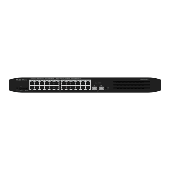
- Page 19 Hardware Installation and Reference Guide Product Overview Front Panel Figure 1-11 Front Panel of the RG-ES226GC-P Note: 1. Power status LED 5. 10/100/1000Base-T auto-sensing Ethernet port 2. Port mode switchover button 6. SFP port 3. System reset button 7. SFP port status LED 4.
- Page 20 Hardware Installation and Reference Guide Product Overview Note: Vent AC power socket Power cord retention clip Protective earthing terminal This device relies on the separate protective earthing terminal. The device installation must be permanently grounded. The device must be intended to be used in a location with equipotential bonding (such as a telecommunication center, a dedicated computer room, or a restricted access area).
-
Page 21: Rg-Es224Gc
Hardware Installation and Reference Guide Product Overview The port is connected at a rate of 10/100/1000 Solid green Mbps. 1000Mbps RJ-45 port status LED The port is receiving or transmitting traffic at a rate Blinking green of 10/100/1000 Mbps. The port is not connected. Solid green The port is connected at a rate of 1000 Mbps . - Page 22 Hardware Installation and Reference Guide Product Overview Certification Earth Leakage ≤ 3.5 mA Current Dimensions 440 mm x 165 mm x 44 mm (W x D x H) Weight 2.8 kg (with package) Device operation in a residential environment may cause radio interference. Product Appearance On the front panel, the RG-ES224GC Ethernet switch provides twenty-four 10/100/1000Base-T Ethernet ports.
- Page 23 Hardware Installation and Reference Guide Product Overview Note: 1. Power status LED 3. 10/100/1000Base-T auto-sensing Ethernet port 2. System reset button 4. Electrical port status LED 5. Nameplate on the bottom of the device The switch restarts after the reset button is pressed for less than 2 seconds. The switch restores the default factory settings after the reset button is pressed for more than 5 seconds (until the status LED blinks).
-
Page 24: Rg-Es216Gc
Hardware Installation and Reference Guide Product Overview Blinking green The switch is being upgraded or initialized. Solid green The switch is operational. The port is not connected. The port is connected at a rate of 10/100/1000 Solid green 1000Mbps RJ-45 1–24 Mbps. - Page 25 Hardware Installation and Reference Guide Product Overview Certification Earth Leakage ≤ 3.5 mA Current Dimensions 440 mm x 165 mm x 44 mm (W x D x H) Weight 2.7 kg (with package) Device operation in a residential environment may cause radio interference. Product Appearance On the front panel, the RG-ES216GC Ethernet switch provides sixteen 10/100/1000Base-T Ethernet ports.
- Page 26 Hardware Installation and Reference Guide Product Overview The switch restarts after the reset button is pressed for less than 2 seconds. The switch restores the default factory settings after the reset button is pressed for more than 5 seconds (until the status LED blinks).
- Page 27 Hardware Installation and Reference Guide Product Overview The port is connected at a rate of 10/100/1000 Solid green Mbps. 1000Mbps RJ-45 port status LED The port is receiving or transmitting traffic at a rate Blinking green of 10/100/1000 Mbps.
-
Page 28: Rg-Es205Gc
Hardware Installation and Reference Guide Product Overview 1.7 RG-ES205GC Technical Specifications Model RG-ES205GC Port Five 10/100/1000 Base-T auto-sensing Ethernet ports AC input Rated voltage range: 100 V to 240 V Maximum voltage range: 90 V to 264 V Frequency: 50/60 Hz Power Supply Rated current: 0.3A ... - Page 29 Hardware Installation and Reference Guide Product Overview Product Appearance On the front panel, the RG-ES205GC Ethernet switch provides five 10/100/1000Base-T Ethernet ports. On the back panel, it provides a DC power socket. Figure 1-19 Appearance of the RG-ES205GC Front Panel Figure 1-20 Front Panel of the RG-ES205GC...
- Page 30 Hardware Installation and Reference Guide Product Overview Note: 1. System status LED 4. Electrical port status LED 2. 10/100/1000Base-T auto-sensing Ethernet port 5. 10/100/1000Base-T auto-sensing Ethernet port 3. Electrical port status LED 6. DC power socket 7. Nameplate on the bottom of the device Back Panel Figure 1-21 Back Panel of the RG-ES205GC Note:...
-
Page 31: Rg-Es208Gc
Hardware Installation and Reference Guide Product Overview Panel Identification State Meaning Blinking green The switch is being upgraded or initialized. Solid green The switch is operational. The port is not connected. The port is connected at a rate of 10/100/1000 RJ-45 port Link/Ack Solid green 1–5... - Page 32 Hardware Installation and Reference Guide Product Overview Temperature Not supported Warning Accessing Optical Module Not supported Information Certification Earth Leakage ≤ 1.5 mA Current Dimensions 160 mm x 75 mm x 24 mm (W x D x H) Weight 0.49 kg (with package) Device operation in a residential environment may cause radio interference.
- Page 33 Hardware Installation and Reference Guide Product Overview Note: 1. System status LED 4. Electrical port status LED 2. 10/100/1000Base-T auto-sensing Ethernet port 5. 10/100/1000Base-T auto-sensing Ethernet port 3. Electrical port status LED 6. DC power socket 7. Nameplate on the bottom of the device Back Panel Figure 1-24 Back Panel of the RG-ES208GC Note:...
-
Page 34: Rg-Es206Gc-P
Hardware Installation and Reference Guide Product Overview Heat Dissipation The RG-ES208GC adopts natural heat dissipation, thereby ensuring normal ope ration. You must reserve 10 cm distance space at both sides and the back plane of the cabinet to allow airflow. It is recommended that you clean the device once every 3 months to avoid dust from blocking vents. - Page 35 Hardware Installation and Reference Guide Product Overview Ports 1 to 4 support PoE/PoE+ with the maximum power output of 30 W per port. Ports 5 and 6 do not support PoE or PoE+. The overall maximum output power of PoE/PoE+ is 54 W. PoE Mode Mode A (data pairs 1-2 and 3-6) Power...
- Page 36 Hardware Installation and Reference Guide Product Overview Front Panel Figure 1-26 Front Panel of the RG-ES206GC-P Note: 1. System status LED 4. Electrical port status LED 2. Port mode switchover button 5. Electrical port status LED 3. 10/100/1000Base-T auto-sensing Ethernet port 6.
- Page 37 Hardware Installation and Reference Guide Product Overview When the button is turned to the right position (Mode 2), the LED indicates the PoE status of ports. When the LED is solid green, the PoE-supported ports are supplying power. When the LED blinks green, the power of the ports is overloaded.
-
Page 38: Rg-Es210Gc-Lp
Hardware Installation and Reference Guide Product Overview Panel Identification State Meaning The PoE power exceeds the power of the entire device (54 W). The newly connected PD cannot Blinking green be powered up due to insufficient power. The switching function is operational. Solid green The switch is operational. - Page 39 Hardware Installation and Reference Guide Product Overview Ports 1 to 8 support PoE/PoE+ with the maximum power output of 30 W per port. Ports 9 and 10 do not support PoE or PoE+. The overall maximum output power of PoE/PoE+ is 70 W. PoE Mode Mode A (data pairs 1-2 and 3-6) Power...
- Page 40 Hardware Installation and Reference Guide Product Overview Front Panel Figure 1-29 Front Panel of the RG-ES210GC-LP Note: 1. System status LED 4. Electrical port status LED 2. Port mode switchover button 5. Electrical port status LED 3. 10/100/1000Base-T auto-sensing Ethernet port 6.
- Page 41 Hardware Installation and Reference Guide Product Overview When the button is turned to the right position (Mode 2), the LED indicates the PoE status of ports. When the LED is solid green, the PoE-supported ports are supplying power. When the LED blinks green, the power of the ports is overloaded.
- Page 42 Hardware Installation and Reference Guide Product Overview Solid green The switch is operational. PoE is not enabled. RJ-45 port 1–8 Solid green PoE is enabled. The port is operational. status LED Blinking green PoE overload. The port is not connected. The port is connected at a rate of 10/100/1000 RJ-45 port Link/Ack Solid green...
-
Page 43: Preparation Before Installation
Hardware Installation and Reference Guide Preparation Before Installation 2 Preparation Before Installation 2.1 Safety Suggestions To avoid personal injury and device damage, carefully read the safety suggestions before you install thee RG -ES200 series switch. The following safety suggestions do not cover all possible dangers. 2.1.1 Installation ... -
Page 44: Static Discharge Damage Prevention
Hardware Installation and Reference Guide Preparation Before Installation power supply is equal to or less than 1.5 mA, and the total leakage current of the system is 30 mA. A leakage protector with 30 mA rated action current supports less than ten power supplies (that is, action current of the leakage protector/2/maximum leakage current of each power supply = 30/2/1 .5 =10). -
Page 45: Ventilation
Hardware Installation and Reference Guide Preparation Before Installation 2.2.1 Ventilation For the RG-ES200 series, a sufficient space (at least 10 cm distances from both sides and the back plane of the cabinet) should be reserved at the ventilation openings to ensure the normal ventilation. After various cables have been connected, they should be arranged into bundles or placed on the cabling rack to avoid blocking the air inlets. -
Page 46: Interference Resistance
Hardware Installation and Reference Guide Preparation Before Installation Diameter ≥ 5 μm ≤ 3×10 Particles/m Apart from dust, the salt, acid, and sulfide in the air in the equipment room must also meet strict requirements. This is because such poisonous substances may accelerate the corrosion of the metal and the aging of some parts. The equipment room should be protected from the intrusion of harmful gases such as sulfur dioxide, sulfured hydrogen, nitrogen dioxide, and chlorine. -
Page 47: Lightning Resistance
Hardware Installation and Reference Guide Preparation Before Installation The device using AC power supply must be grounded by using the yellow/green safety grounding cable. Otherwise, when the insulating resistance decreases the power supply and the enclosure in the equipment, electric shock may occur. The building must provide the protective grounding connection to ensure that the device is connected to the protection location. -
Page 48: Emi
Hardware Installation and Reference Guide Preparation Before Installation AC cable to the lightning line bank, and connect the switch to the lightning line bank. This helps prevent the current of high- voltage lightning from passing the switch directly through the mains supply cable to a certain extent. The lightning line banks are not provided and should be purchased by customers as required . -
Page 49: Product Installation
Hardware Installation and Reference Guide Product Installation 3 Product Installation 3.1 Installation Flowchart 3.2 Confirmations Before Installation Before installation, confirm the following points:... -
Page 50: Installing The Rg-Es200
Hardware Installation and Reference Guide Product Installation Check whether ventilation requirements are met for the switch. Check whether the requirements of temperature and humidity are met for the switch. Check whether power cables are already laid out and whether the requirements of electrical current are met. ... - Page 51 Hardware Installation and Reference Guide Product Installation Figure 3-3 Attaching the Mounting Bracket to the RG-ES224GC or RG-ES216GC Step 2: Use the supplied M6 screws and cage nuts to securely attach the mounting brackets to the rack, as shown in Figure 3-4 and Figure 3-5.
-
Page 52: Mounting The Switch Against A Wall
Hardware Installation and Reference Guide Product Installation 3.3.2 Mounting the Switch Against a Wall The RG-ES209GC-P, RG-ES205GC, RG-ES208GC, RG-ES206GC-P, and RG-ES210GC-LP can be mounted against the wall. Mounting screws and wall anchors are customer-supplied. You need to determine the size and depth of the two mounting holes on the wall based on the sizes of wall anchors and screws. -
Page 53: Mounting The Switch On A Table
Hardware Installation and Reference Guide Product Installation It is suitable for mounting on the concrete or non-combustible surface only. 3.3.3 Mounting the Switch on a Table Attach the four rubber pads to the recessed areas on the bottom of the switch, as shown in Figure 3-7 and Figure 3-8. Figure 3-7 Attaching the Rubber Feet to the Recessed Areas Figure 3-8 Attaching the Rubber Pads to the Recessed Areas... - Page 54 Hardware Installation and Reference Guide Product Installation Place the switch on the table, as shown in Figure 3-9 and Figure 3-10. Figure 3-9 Mounting the Switch on the Table Figure 3-10 Mounting the Switch on the Table...
-
Page 55: Checking After Installation
Hardware Installation and Reference Guide Product Installation The device must be installed and operated in the place that can restrict its movement. 3.4 Checking After Installation Before checking the installation, switch off the power supply so as to avoid any personal injury or damage to the component due to connection errors . -
Page 56: System Check
Hardware Installation and Reference Guide System Check 4 System Check 4.1 Startup Check 4.1.1 Checking Before the Device Is Powered On The switch is well grounded. The power cable is correctly connected. The power supply voltage complies with the requirement of the switch. 4.1.2 Checking After Program Startup (Recommended) After power-on, you are advised to perform the following checks to ensure the normal operation of follow -up configurations. -
Page 57: Maintenance And Troubleshooting
Maintenance and Troubleshooting 5 Maintenance and Troubleshooting 5.1 Troubleshooting Procedure 5.2 Troubleshooting Common Faults Symptom Possible Causes Solution management A password is manually configured but Contact Ruijie Networks Customer Service interface login it is forgotten. Department for technical support. password is forgotten. - Page 58 Hardware Installation and Reference Guide Maintenance and Troubleshooting Symptom Possible Causes Solution occurs when the port is The length of the cable exceeds 100 m. Check that the working mode of the port must adapt receiving The port has special configuration that to that of the connected switch.
-
Page 59: Appendix A Connectors And Connection Media
Hardware Installation and Reference Guide Appendix A Connectors and Connection Media Appendix A Connectors and Connection Media 1000BASE-T/100BASE-TX/10BASE-T Ports The 1000BASE-T/100BASE-TX/10BASE-T supports adaptation of three rates and automatic MDI/MDIX crossover at these three rates. The 1000BASE-T complies with IEEE 802.3ab, and uses the cable of 100-ohm Category-5 or Supper Category-5 UTP or STP, which can be up to 100 m. - Page 60 Hardware Installation and Reference Guide Appendix A Connectors and Connection Media Optical Fiber Connection For the optical fiber ports, select single-mode or multimode optical fibers for connections according to the optical module connected. Figure A-4 shows the connection schematic diagram. Figure A-4 Optical Fiber Connections...
-
Page 61: Appendix B Mini-Gbic And Spf+ Module
You can select the mini-GBIC module to suit your specific needs. The models and technical specifications of some min i- GBIC and 10G SFP+ modules are listed below. For details, see Ruijie Transceiver Installation and Reference Guide. Table B-1 Models and Technical Specifications of the 1000M Mini-GBIC (SFP) Module... - Page 62 Hardware Installation and Reference Guide Appendix B Mini-GBIC and SPF+ Module Interface Cable Distance Type (Max.) 62.5/125 275 m Mini-GBIC-SX-MM850 50/125 550 m Mini-GBIC-LX-SM1310 9/125 10 km 62.5/125 275 m GE-eSFP-SX-MM850 50/125 550 m GE-eSFP-LX-SM1310 9/125 10 km GE-SFP-LX-SM1310 9/125 10 km Mini-GBIC-LH40-SM1310 9/125...
- Page 63 Hardware Installation and Reference Guide Appendix B Mini-GBIC and SPF+ Module The BIDI modules must be used in pairs , for example, FE-SFP-LX20-SM1310-BIDI and FE-SFP-LX20-SM1550-BIDI are used together.
-
Page 64: Appendix C Lightning Protection
Hardware Installation and Reference Guide Appendix C Lightning Protection Appendix C Lightning Protection Installing the AC Power Arrester (Lightning Protection Cable Row) The external lightning protection cable row must be used on the AC power port to prevent the switch from being struck by lightning when the AC power cable is introduced from the outdoor and directly connected to the power port of the switch. - Page 65 Hardware Installation and Reference Guide Appendix C Lightning Protection Installing the Ethernet Port Arrester During the switch usage, the Ethernet port arrester must be connected to the switch to prevent the switch damage by lightning before the outdoor network cable connects to the switch. Tools: cross or straight screwdriver, multimeter, and diagonal pliers Installation steps: Tear one side of the protection paper for the double-sided adhesive tape and paste the tape to the framework of the...
- Page 66 Hardware Installation and Reference Guide Appendix C Lightning Protection To prevent the performance of the Ethernet port arrester from being affected, note the following points: Reversed direction of the arrester installation: Connect the external network cable to the IN end and connect the switch Ethernet port to the OUT end.
-
Page 67: Appendix D Cabling Recommendations In Installation
Hardware Installation and Reference Guide Appendix D Cabling Recommendations in Installation Appendix D Cabling Recommendations in Installation When RG-ES200 series switches are installed in s tandard 19-inch cabinets, cables are tied in the binding rack on the cabinet by the cabling rack, and top or bottom cabling is adopted according to the actual situation in the equipment room. All cable connectors should be placed at the bottom of the cabin et in an orderly manner but not outside the cabinet. - Page 68 Hardware Installation and Reference Guide Appendix D Cabling Recommendations in Installation Cables of different types (such as power cords, signal cables, and g round cables) should be separated in cabling and bundling. When they are close, crossover cabling can be adopted. In the case of parallel cabling, maintain a space of at least 30 mm for power cords and signal cables.
- Page 69 Hardware Installation and Reference Guide Appendix D Cabling Recommendations in Installation Cables not to be assembled or remaining parts of cables should be folded and placed in a proper position of the cabinet or cabling slot. The proper position will not affect device running or cause device or cable damage during commissioning.
- Page 70 Hardware Installation and Reference Guide Appendix D Cabling Recommendations in Installation The hard power cable should be fastened by the terminal connection area to prevent stress. Do not use self-tapping screws to fasten terminals. Power cables of the same type in the same cabling direction should be bundled up into cable bunches, with clean and straight cables in cable bunches.
-
Page 71: Appendix E Site Selection
Hardware Installation and Reference Guide Appendix E Site Selection Appendix E Site Selection The equipment room should be at least 5 km away from the heavy pollution source such as the smelter, coal mine , and thermal power plant, 3.7 km away from the medium pollution source such as the chemical industry, rubber industry, and electroplating industry, and 2 km away from the light pollution source such as the food manufacturer and leather plant.
Need help?
Do you have a question about the Reyee RG-ES200 Series and is the answer not in the manual?
Questions and answers