
Related Manuals for Ruijie Reyee RG-ES206GS-P Series


Summary of Contents for Ruijie Reyee RG-ES206GS-P Series
- Page 1 RG-ES206GS-P Series Switches Hardware Installation and Reference Guide Document Version: V1.0 Date: 2023.09.11 Copyright © 2023 Ruijie Networks...
- Page 2 Ruijie Networks reserves the right to modify the content of the document without any notice or prompt. This manual is designed merely as a user guide. Ruijie Networks has tried its best to ensure the accuracy and reliability of the content when compiling this manual, but it does not guarantee that the content of the manual is completely free of errors or omissions, and all the information in this manual does not constitute any explicit or implicit warranties.
- Page 3 Intended Audience This document is intended for: Network engineers Technical support and servicing engineers Network administrators Technical Support The official website of Ruijie Reyee: https://www.ruijienetworks.com/products/reyee Technical Support Website: https://www.ruijienetworks.com/support Case Portal: https://caseportal.ruijienetworks.com Community: https://community.ruijienetworks.com...
-
Page 4: Product Overview
RG-ES206GS-P Series Switches Hardware Installation and Reference Guide Product Overview Product Overview The RG-ES200 series switches include the following 10 models: 10/100/1000Base-T 10/100Base-T Ports with 1000Base- Consol Model Ports with Auto-Negotiation X SFP Port e Port Auto-Negotiation 5 (Ports 1-4 support RG-ES205C-P PoE/PoE+) RG-ES205GC-... -
Page 5: Package Contents
RG-ES206GS-P Series Switches Hardware Installation and Reference Guide Product Overview ● 1000Base-T ports are downward compatible with 100Base-TX and 10Base-T ports. Package Contents Table 1-1 RG-ES206GS-P Package Contents Item Quantity Switch Power adapter User Manual Power cord Warranty card Note The package contents above are intended to provide a general overview, and are subject to the terms of the order contract. - Page 6 RG-ES206GS-P Series Switches Hardware Installation and Reference Guide Product Overview Not supported PoE standards: IEEE802.3af and 802.3at. Ports 1-4 are PoE/PoE+ ports, each supporting a maximum PoE+ output of 30 W. Ports 5 and 6 do not support PoE standard. Overall max.
-
Page 7: Product Appearance
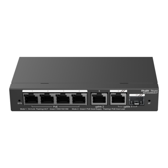
RG-ES206GS-P Series Switches Hardware Installation and Reference Guide Product Overview Caution Operation of this equipment in a residential environment could cause radio interference. Product Appearance The RG-ES206GS-P switch provides 8 × 10/100/1000Base-T ports on the front panel, and a DC power input port for 54V PoE injector on the back panel. - Page 8 RG-ES206GS-P Series Switches Hardware Installation and Reference Guide Product Overview Figure 1-3 Back Panel of RG-ES206GS-P Note 1. Grounding stud 4. DC power input 2. Reset button 5. Kensington lock 3. LED mode switch Note ● Reset button: Press for less than 2 seconds and release, the system restarts; press for more than 5 seconds until the system LE blinks, and then release, the system restores to factory settings and restarts.
- Page 9 RG-ES206GS-P Series Switches Hardware Installation and Reference Guide Product Overview the RJ-45 port Solid PoE is enabled. green Blinking PoE is abnormal. green No link is detected for this port. Solid RJ-45 Port Link/Ack The port operates 10/100/1000 Mbps. 1–6 green Status LED Blinking...
-
Page 10: Preparing For Installation
RG-ES206GS-P Series Switches Hardware Installation and Reference Guide Preparing for Installation Preparing for Installation Safety Precautions Caution ● To avoid personal injury and device damage, carefully read the safety precautions before you install the device. ● The following safety precautions may not cover all possible dangers. 2.1.1 Installation Safety ... -
Page 11: Electrostatic Discharge Safety
RG-ES206GS-P Series Switches Hardware Installation and Reference Guide Preparing for Installation if a system is equipped with 20 identical power supplies and the leakage current of each power supply is equal to or less than 1.5 mA, the leakage current of the system totals 30 mA. A leakage protector with 30 mA rated action current supports less than ten power supplies (that is, Action current of the leakage protector/2/Maximum leakage current of each power supply = 30/2/1.5 = 10). -
Page 12: Ventilation And Cooling Requirements
RG-ES206GS-P Series Switches Hardware Installation and Reference Guide Preparing for Installation 2.2.1 Ventilation and Cooling Requirements Maintain a minimum clearance of 100 mm (3.94 in.) around the switch for air circulation and ventilation. After various cables are connected, bundle the cables or place them in the patch panel to avoid blocking air inlets. Dust the device every three months to avoid blocking the ventilation openings on the housing. -
Page 13: Grounding Requirements
RG-ES206GS-P Series Switches Hardware Installation and Reference Guide Preparing for Installation Sulfur dioxide (SO Hydrogen sulfide Nitrogen dioxide (NO Chlorine gas (CI Specification Average refers to the average value of harmful gases measured in one week. The Maximum value is the upper limit of the harmful gas measured in one week for up to 30 minutes every day. -
Page 14: Lightning Protection Requirements
RG-ES206GS-P Series Switches Hardware Installation and Reference Guide Preparing for Installation ● The cross-sectional area of the protective ground cable should be at least 0.75 mm (18 AWG). ● Install the switch by using 3-core power cords, with a minimum cross-sectional area of 0.75 mm 18AWG per pin. - Page 15 RG-ES206GS-P Series Switches Hardware Installation and Reference Guide Preparing for Installation and a completely electrically isolated unit. Conducted interference occurs when interference is transferred from one unit to another through cables which are usually electromagnetic wires or signal cables connecting the source and the sensor.
-
Page 16: Installing The Switch
RG-ES206GS-P Series Switches Hardware Installation and Reference Guide Installing the switch Installing the switch Specification ● Before reading chapter 3 "Product Installation", ensure that you have read chapter 2 carefully. ● Verify that requirements described in chapter 2 have been met. Installation Procedure Before You Begin Confirm the following requirements before installation:... -
Page 17: Installing The Switch In A Rack
RG-ES206GS-P Series Switches Hardware Installation and Reference Guide Installing the switch power cord is securely inserted into the device, fasten the power cord with power cord retention clips. Do not place anything on the top of the switch. Maintain a minimum clearance of 100 mm (3.94 in.) around the device to ensure proper airflow. - Page 18 RG-ES206GS-P Series Switches Hardware Installation and Reference Guide Installing the switch Figure 3-3 Securing Mounting Brackets Step 4: As shown in Figure 3-4, horizontally mount the device to an appropriate position inside the rack and use M6 screws and cage nuts to secure the other end of the mounting brackets to square-hole posts of the rack. Figure 3-4 Securing Mounting Brackets Figure 3-5...
-
Page 19: Mounting The Switch On The Wall
RG-ES206GS-P Series Switches Hardware Installation and Reference Guide Installing the switch 3.3.2 Mounting the Switch on the Wall RG-ES206GS-P, RG-ES210GS-P, RG-ES209C-P, RG-ES209GC-P, RG-ES205GC (only can be mounted vertically), RG-ES208GC, RG-ES206GC-P, and RG-ES210GC-LP can be mounted on a wall. (Screws and wall anchors for installation are not provided, and needs to be purchased by the customer). -
Page 20: Verifying Installation
RG-ES206GS-P Series Switches Hardware Installation and Reference Guide Installing the switch Verifying Installation Caution Turn off the power to avoid personal injury and damage to components caused by incorrect connection. Verify that the ground wire is connected. Verify that the Ethernet cables and power cords are properly connected. ... -
Page 21: System Check
RG-ES206GS-P Series Switches Hardware Installation and Reference Guide System Check System Check Checking the Device Startup Check Before Device Power-On Check that the switch is fully grounded. The power cord is properly connected. The power supply voltage meets the requirement of the switch. Check After Program Startup (Recommended) After the switch is powered on, you are advised to check the following items to ensure the normal configuration: ... -
Page 22: Common Troubleshooting
RG-ES206GS-P Series Switches Hardware Installation and Reference Guide Common Troubleshooting Common Troubleshooting Troubleshooting Flowchart Common Troubleshooting Fault Symptom Possible Cause Suggested Action Check whether the power socket in the The status indicator No power is supplied to the switch equipment room is normal and whether is off after the device or the power cord is loose. - Page 23 RG-ES206GS-P Series Switches Hardware Installation and Reference Guide Common Troubleshooting Rx and Tx ends are connected incorrectly. Connect the Rx and Tx ends of the fiber correctly. The types of the interconnected optical modules do not match. Replace optical modules with those of An optical port the same type.
-
Page 24: Appendix A - Connectors And Media
Appendix A — Connectors and Media RG-ES206GS-P Series Switches Hardware Installation and Reference Guide Appendix A — Connectors and Media 1000BASE-T/100BASE-TX/10BASE-T Port The 1000BASE-T/100BASE-TX/10BASE-T is a 10/100/1000 Mbps auto-negotiation port that supports auto MDI/MDIX Crossover. Compliant with IEEE 802.3ab, 1000BASE-T requires Category 5e 100-ohm UTP or STP (recommended) with a maximum distance of 100 meters (328 feet). - Page 25 Appendix A — Connectors and Media RG-ES206GS-P Series Switches Hardware Installation and Reference Guide Optical Fiber Connection Choose single mode or multi-mode fibers according to the module types. Figure A-4 Optical Fiber Connection - 22 -...
-
Page 26: Appendix B - Mini-Gbic And Sfp Modules
Besides, the Mini-GBIC-GT modules are also supported. The following models and technical specifications of some SFP modules are listed for your reference. For details about the technical specifications, see Ruijie Transceiver Installation and Reference Guide. Table B-1 Models and Specifications of 1000M Mini-GBIC (SFP) Optical Modules... - Page 27 RG-ES206GS-P Series Switches Hardware Installation and Reference Guide Appendix B — Mini-GBIC and SFP Modules GE-SFP-LH40-SM1550-BI /1310R Appearance of the 1550 MINI-GBIC-ZX50-SM1550 Appearance of the 1550 MINI-GBIC-ZX80-SM1550 Appearance of the 1550 MINI-GBIC-ZX100-SM1550 GE-SFP-SX -9.5 GE-SFP-LX 1310 -9.5 Appearance of the -9.5 SFP-MM850 Appearance of the...
- Page 28 RG-ES206GS-P Series Switches Hardware Installation and Reference Guide Appendix B — Mini-GBIC and SFP Modules GE-SFP-SX-SM1310-BIDI Appearance of the 50/125 500 m GE-SFP-SX-SM1550-BIDI Appearance of the 9/125 20 km GE-SFP-LX20-SM1310-BIDI Appearance of the 9/125 20 km GE-SFP-LX20-SM1550-BIDI Appearance of the 9/125 40 km GE-SFP-LH40-SM1310-BIDI...
- Page 29 RG-ES206GS-P Series Switches Hardware Installation and Reference Guide Appendix B — Mini-GBIC and SFP Modules Appearance of the GE-SFP-LX20-SM1550-BIDI Appearance of the GE-SFP-LH40-SM1310-BIDI 1 Gbps/40 km Appearance of the GE-SFP-LH40-SM1550-BIDI Note The BIDI modules must be used in pairs. For example, if you install the GE-SFP-LX20-SM1310-BIDI in the local port, you must install the GE-SFP-LX20-SM1550-BIDI in the peer port.
-
Page 30: Appendix C - Lightning Protection
Appendix C — Lightning Protection RG-ES206GS-P Series Switches Hardware Installation and Reference Guide Appendix C — Lightning Protection Installing an AC Power Arrester (Lightning Resistance Socket) When an AC power cord is introduced from outdoors and directly connected to the power port of the switch, the AC power port must be connected to an external lightning protection power strip to protect the switch against lightning strokes. - Page 31 Appendix C — Lightning Protection RG-ES206GS-P Series Switches Hardware Installation and Reference Guide grounded. Installing the Ethernet Port Arrester Connect an Ethernet port arrester to the switch to prevent the damage by lightning before connecting an outdoor network cable to the switch. Tools: Phillips screwdrivers or flat-head screwdriver, multimeter, and diagonal pliers Installation Steps: (1) Tear one side of the protective paper for the double-sided adhesive tape and paste the tape to the enclosure...
- Page 32 Appendix C — Lightning Protection RG-ES206GS-P Series Switches Hardware Installation and Reference Guide ● The Ethernet port arrester is not delivered with the switch. Please purchase it based on actual requirements. ● The Ethernet port arrester user manual contains technical parameters and maintenance and installation instructions for the Ethernet port arrester.
-
Page 33: Appendix D - Cabling Recommendations
RG-ES206GS-P Series Switches Hardware Installation and Reference Guide Appendix D — Cabling Recommendations Appendix D — Cabling Recommendations When the switch is installed in a standard 19-inch rack, secure the cables around the cable management brackets. Adopt top cabling or bottom cabling according to the actual situation in the machine room. All cable connectors used for transit should be placed at the bottom of the cabinet rather than be exposed outside of the cabinet. - Page 34 RG-ES206GS-P Series Switches Hardware Installation and Reference Guide Appendix D — Cabling Recommendations Cables of different types (such as power cords, signal cables, and ground cables) should be separated in cabling and bundling. Mixed bundling is disallowed. When they are close to each other, you are advised to adopt crossover cabling.
- Page 35 RG-ES206GS-P Series Switches Hardware Installation and Reference Guide Appendix D — Cabling Recommendations Figure D-3 Binding Cables (3) Cables not to be assembled or remaining parts of cables should be folded and placed in a proper position of the rack or cable trough. The proper position refers to a position that does not affect device running or damage the switch or cable.
- Page 36 RG-ES206GS-P Series Switches Hardware Installation and Reference Guide Appendix D — Cabling Recommendations Hard power cords should be fastened in the terminal connection area to prevent stress on terminal connection and cable. Do not use self-tapping screws to fasten terminals. ...
-
Page 37: Appendix E - Machine Room Site Selection
RG-ES206GS-P Series Switches Hardware Installation and Reference Guide Appendix E — Machine Room Site Selection Appendix E — Machine Room Site Selection The machine room should be at least 5 km (3.11 miles) away from heavy pollution sources, such as the smelter works, coal mine, and thermal power plant.
Need help?
Do you have a question about the Reyee RG-ES206GS-P Series and is the answer not in the manual?
Questions and answers