Table of Contents
Advertisement
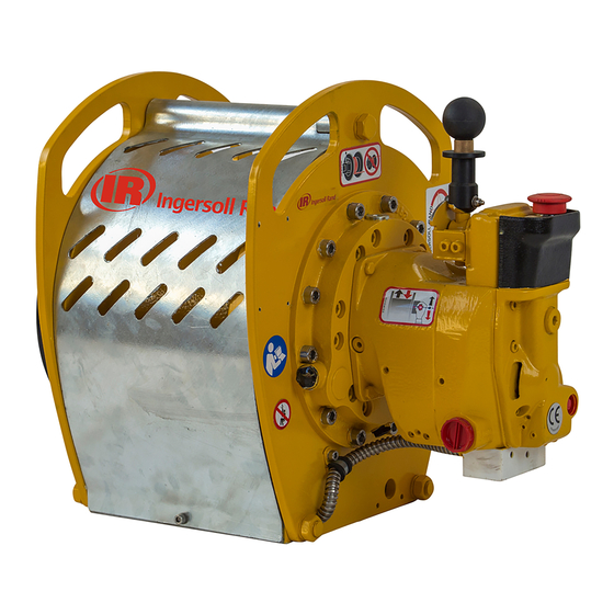
Product Maintenance
Information
LS2–300R, LS2–600R, PS2–1000R, LS2–1500R, PS2–2400R
LS2–300R( )-E and CE, LS2–600R( )-E and CE, LS2–1500R( )-E and CE,
PS2–1000R( )-E and CE and PS2–2400R( )-E
(Dwg. MHP2628)
Save These Instructions
Liftstar and Pullstar
Air Winch Models
LS2–1500R( )-CE
R
Form MHD56276
Edition 3
January 2016
71432298
2016
©
Ingersoll Rand
Advertisement
Table of Contents

Related Manuals for Ingersoll-Rand LS2-300R E Series


Summary of Contents for Ingersoll-Rand LS2-300R E Series
- Page 1 Product Maintenance Information Liftstar and Pullstar Air Winch Models LS2–300R, LS2–600R, PS2–1000R, LS2–1500R, PS2–2400R LS2–300R( )-E and CE, LS2–600R( )-E and CE, LS2–1500R( )-E and CE, LS2–1500R( )-CE PS2–1000R( )-E and CE and PS2–2400R( )-E (Dwg. MHP2628) Save These Instructions Form MHD56276 Edition 3 January 2016...
-
Page 2: Records And Reports
Only allow trained technicians to perform maintenance on this product. For additional information contact factory or nearest Ingersoll Rand Ingersoll Rand Distributor. For additional supporting documentation refer to Table 1 ‘Product Information Manuals’ on page 2. Manuals can be downloaded from ingersollrandproducts.com The use of other than genuine Ingersoll Rand replacement parts may result in safety hazards, decreased performance and increased maintenance and will invalidate all warranties. -
Page 3: Inspection Report
INSPECTION REPORT Ingersoll Rand Models LS2–300R, LS2–600R, LS2–1500R, PS2–1000R or PS2–2400R Air Winch Model Number: Date: Serial Number: Inspected by: Reason for Inspection: (Check Applicable Box) 1. Scheduled Periodic Inspection: (_____ Months _____ Years) Operating Environment: Normal ____ Heavy____ Severe ____ 2. -
Page 4: Troubleshooting
TROUBLESHOOTING This section provides basic troubleshooting information. Determination of specific causes to problems are best identified by thorough inspections performed by personnel instructed in safety, operation and maintenance of this equipment. The chart below provides a brief guide to common winch symptoms, probable causes and remedies. SYMPTOM CAUSE REMEDY... -
Page 5: Maintenance
MAINTENANCE 4. Remove four capscrews (86) and lockwashers (2) that attach air motor assembly WARNING to the upright (5) and remove motor assembly. 5. Store motor in a clean area until further disassembly is necessary. • Never perform maintenance on the winch while it is supporting a load. •... - Page 6 3. Position several blocks of wood on the work bench and put the winch in a vertical Overload Device position with the motor end up. If winch is equipped with a free spool option, make sure the weight of the winch does not rest on the free spool knob (238) or cause damage to the free spool parts.
-
Page 7: Cleaning, Inspection And Repair
2. Remove emergency stop (179) from end cover (183). Remove ‘O’ rings (175). NOTICE 3. Loosen the emergency stop button (164). Remove retainer rings (178). 4. Remove springs (177) and balls (84). • It may be necessary to use small quantity of air pressure in fill hole of 5. -
Page 8: Winch Assembly
2. Inspect all remaining parts for evidence of damage. Replace or repair any part 1. If bearing was removed, install bearing (38) into brake housing (69). which is in questionable condition. The cost of the part is often minor in 2. - Page 9 25. After applying a large quantity of grease (grease : UNIL OPAL HT 300 or Control Valve Assembly equivalent) on the spline. Install ‘O’ rings (18) and spacer ring (34) on sungear. Refer to Dwg. MHP2622 or Dwg. MHP3718. Aligned Teeth Timing Mark The assembly is in opposite order of the disassembly.
-
Page 10: Operational Tests
2. Install cover (102) and attach with capscrews (44). 5. Install piston into brake housing (69). Install gasket (26) on motor housing (87). 6. Install two plugs (167). 7. Install the brake housing into motor housing (87). Partially lift out and turn the Motor with Emergency Stop and Overload Assembly motor to align splines in the splined hub (75) and on drive gear (92). -
Page 11: Torque Chart
TORQUE CHART Standard Coarse Thread Torque SAE Grade 5 SAE Grade 8 Size Lubricated PTFE Lubricated PTFE 1/4-20 8-10 12-14 9-10 5/16-18 17-20 13-15 25-28 18-21 11-13 3/8-16 31-35 23-26 14-16 44-49 33-37 20-22 7/16-14 49-56 37-42 22-25 70-79 52-59 31-36 1/2-13 75-85... - Page 12 ingersollrandproducts.com...
Need help?
Do you have a question about the LS2-300R E Series and is the answer not in the manual?
Questions and answers