
Subscribe to Our Youtube Channel
Related Manuals for Ingersoll-Rand Man Rider MR150K Series


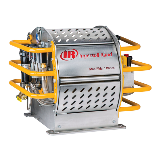
Summary of Contents for Ingersoll-Rand Man Rider MR150K Series
- Page 1 Product Information Air Powered Man Rider Winch MR150K Series (Dwg. MHP3377) Save These Instructions Form MHD56490 Edition E March 2016 45757115 2016 Ingersoll Rand ©...
-
Page 2: Product Description And Intended Use
ORIGINAL INSTRUCTIONS Only allow Ingersoll Rand trained technicians to perform maintenance on this product. For additional information contact Ingersoll Rand factory or nearest Distributor. Manuals can be downloaded from http://www.ingersollrandproducts.com. The use of other than genuine Ingersoll Rand replacement parts may result in safety hazards, decreased performance and increased maintenance and will invalidate all warranties. -
Page 3: Specifications
SPECIFICATIONS Model Code Explanation Example: MR150KA-1CE-B 150K Man Rider 150K Capacity 150 kg / 330 lbs Air Power Source Lever Throttle Control Remote Pilot Pendent (xx hose in m) Certification: Standard (European Standards) CE and ABS Certified CE and DNV Certified Options (Other): Manual Wire Rope Guide Pedestal Base... -
Page 4: Installation
CAUTION • Requirements must be stated when reordering load bearing parts for continued certification. Refer to the Product Parts Information for specific part numbers. Material not designed for cold weather may result in damage to the product. INSTALLATION Prior to installing the product, carefully inspect it for possible shipping damage. Products are supplied fully lubricated from the factory. - Page 5 Rigging n Wire Rope The sheave arrangement with fastening to structure shall be dimensioned according to the same principle as the winch itself. The geometry shall ensure free path for the CAUTION person lifted or lowered and ensure no damage to wire rope. The geometry shall ensure that the angle between wire rope and drum or sheave is within +/- 4 degrees.
-
Page 6: Operation
6. Repeat steps 1 through 5 operations for the second cam. CAUTION 7. Test the winch set points by operating winch through three complete cycles to make sure the limits are within +/- 0.5 m of set points. 8. Once settings are at the desired limits close the access cover (278) and tighten •... -
Page 7: Emergency Lowering
4. Continue to hold both the switches in the actuated position in order to lower the person safely to the ground. n Slack Line Device NOTICE Refer to Dwg. MHP3378 on page 10. • After each use of the emergency lowering device, reset the Emergency Stop The slack wire rope device is intended to detect slack in the wire rope during time Valve and verify the main air supply is in proper working condition and able of operation in the payout direction. - Page 8 11. Wire Rope Spooling: Visually check reeving and make sure the wire rope feeds No part of the winch has been welded onto. Fasteners - Check external retainer rings, split pins, capscrews, nuts and other on and off the drum smoothly. Verify spooling direction is correct for winch and application.
-
Page 9: General Lubrication
ADJUSTMENTS 2. Tighten nut ‘A’ until the adjustment dimension 0.43 to 0.51 inch (11 to 13 mm) is achieved. n Overload Device 3. Tighten locknut ‘B’. 4. Check brake operation. WARNING • Overload is factory set and sealed with red paint and should not be adjusted without consulting an Ingersoll Rand trained technician. - Page 10 PRODUCT INFORMATION GRAPHICS 10° -20° -5° -5° 10° 30° -20° -60° -60° -100° Roller and Weight S ta rting Rop e End ing Rop e Ang le (de gree ) Ang le (de gree ) Positions -- - -- - - 20 -- - - 20...
- Page 11 PRODUCT INFORMATION GRAPHICS CONTINUED Dead End of Wire Rope Wire Rope Anchor “Emergency Stop” Button “ON” Button Function Levers (Dwg. MHP3380) Pendant Handle (Dwg. MHP1892) Lift Slider Handle UP to Unlock To Regulator / Filter / Water Separator Payout Emergency Stop Haul-In Button...
-
Page 12: Declaration Of Conformity
DECLARATION OF CONFORMITY DECLARATION OF CONFORMITY (CS) PROHLÁŠENÍ O SHODĚ (DA) OVERENSSTEMMELSESERKLÆRING (DE) KONFORMITÄTSERKLÄRUNG (EL) ∆ΗΛΩΣΗ ΑΝΑΓΝΩΡΙΣΗΣ (ES) DECLARACIÓN DE CONFORMIDAD (FI) VAKUUTUS NORMIEN TÄYTTÄMISESTÄ (FR) CERTIFICAT DE CONFORMITÉ (HU) MEGFELELŐSÉGI NYILATKOZAT (IT) DICHIARAZIONE DI CONFORMITÀ (LT) ATITIKTIES DEKLARACIJA (LV) ATBILSTĪBAS DEKLARĀCIJA (NL) SCHRIFTELIJKE VERKLARING VAN CONFORMITEIT (NO) KONFORMITETSERKLÆRING (PT) DECLARAÇÃO DE CONFORMIDADE (PL) DEKLARACJA ZGODNOŚCI (SK) PREHLÁSENIE O ZHODE (SL) IZJAVA O SKLADNOSTI (SV) FÖRSÄKRAN OM ÖVERENSSTÄMMELSE Company: Ingersoll Rand... - Page 13 DECLARATION OF CONFORMITY DECLARATION OF CONFORMITY (CS) PROHLÁŠENÍ O SHODĚ (DA) OVERENSSTEMMELSESERKLÆRING (DE) KONFORMITÄTSERKLÄRUNG (EL) ∆ΗΛΩΣΗ ΑΝΑΓΝΩΡΙΣΗΣ (ES) DECLARACIÓN DE CONFORMIDAD (FI) VAKUUTUS NORMIEN TÄYTTÄMISESTÄ (FR) CERTIFICAT DE CONFORMITÉ (HU) MEGFELELŐSÉGI NYILATKOZAT (IT) DICHIARAZIONE DI CONFORMITÀ (LT) ATITIKTIES DEKLARACIJA (LV) ATBILSTĪBAS DEKLARĀCIJA (NL) SCHRIFTELIJKE VERKLARING VAN CONFORMITEIT (NO) KONFORMITETSERKLÆRING (PT) DECLARAÇÃO DE CONFORMIDADE (PL) DEKLARACJA ZGODNOŚCI (SK) PREHLÁSENIE O ZHODE (SL) IZJAVA O SKLADNOSTI (SV) FÖRSÄKRAN OM ÖVERENSSTÄMMELSE Company: Ingersoll Rand...
-
Page 14: Service Notes
SERVICE NOTES Form MHD56490 Edition E... - Page 15 SERVICE NOTES Form MHD56490 Edition E...
- Page 16 ingersollrandproducts.com...
Need help?
Do you have a question about the Man Rider MR150K Series and is the answer not in the manual?
Questions and answers