Table of Contents

Subscribe to Our Youtube Channel
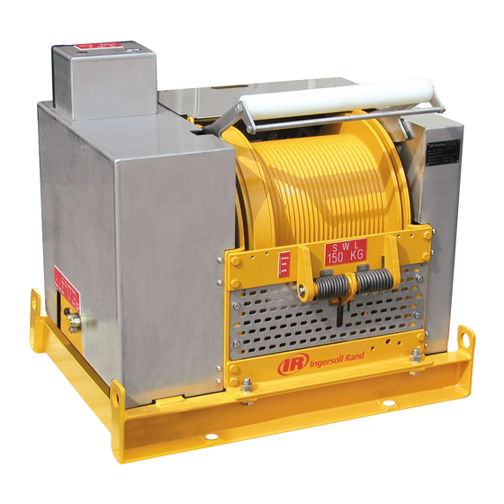
Summary of Contents for Ingersoll-Rand Man Rider LS2-150RLP-L E Series
- Page 1 Product Maintenance Information Air Powered Man Rider™ Winch Models LS2–150RLP-L-( )-E LS2–150RLP-PHXXM-( )-E (Lever Control) (Remote Control) Save These Instructions Form MHD56305 Edition 4 October 2013 71455570 2013 Ingersoll-Rand ©...
-
Page 2: Periodic Inspection
Only allow trained technicians to perform maintenance on this product. For additional information contact factory or nearest Ingersoll Rand Ingersoll Rand Distributor. For additional supporting documentation refer to Table 1 ‘Product Information Manuals’ on page 2. Manuals can be downloaded from http://www.ingersollrandproducts.com. The use of other than genuine Ingersoll Rand replacement parts may result in safety hazards, decreased performance and increased maintenance and will invalidate all warranties. -
Page 3: Maintenance Intervals
12. Slack Line Detector. Inspect rollers for wear and grooves or ridges. Replace worn or grooved rollers. Check arms move freely and activate sensor valve. n Maintenance Intervals Ensure rollers rotate freely. Check sensor valve plunger operation. If damaged or stiff, replace sensor valve. Refer to Table 4 ‘Maintenance Interval Chart’... - Page 4 Table 5: Maintenance Interval Chart Heavy Application The following work can be completed by owner maintenance personnel System Air Filter Inspect system air filter every 30 days or 80 hours Grease Fittings Lubricate grease fittings every 90 days or 250 hours Gearbox Oil Level Check oil level in gearbox every 90 days or 250 hours It is recommended that the following work be completed by an Ingersoll Rand trained service technician.
-
Page 5: Inspection Report
INSPECTION REPORT Ingersoll Rand L2–150RLP Series Air Winches Model Number: Date: Serial Number: Inspected by: Reason for Inspection: (Check Applicable Box) 1. Scheduled Periodic Inspection: (_____ Months _____ Years) Operating Environment: 2. Discrepancy(s) noted during Frequent Inspection Normal ____ Heavy____ Severe ____ 3. -
Page 6: Troubleshooting
TROUBLESHOOTING This section provides basic troubleshooting information. Determination of specific causes to problems are best identified by thorough inspections performed by personnel instructed in safety, operation and maintenance of this equipment. The chart below provides a brief guide to common winch symptoms, probable causes and remedies. SYMPTOM CAUSE REMEDY... -
Page 7: Maintenance
MAINTENANCE WARNING n Adjustments • Never perform maintenance on the winch while it is supporting a load. Limit Switches • Before performing maintenance, tag controls: Refer to Limit Switches section in Product Information Manual. WARNING - DO NOT OPERATE, EQUIPMENT BEING REPAIRED. Disc Brake •... - Page 8 Automatic Band Drum Brake Motor and Reduction Gear Removal Refer to Dwg. MHP2880 on page 8. Refer to Dwg. MHP2812 and MHP2728. 1. Loosen locknut ‘B’. 1. Shut off and bleed down main air supply to winch. 2. Tighten nut ‘A’ until the adjustment dimension 0.43 to 0.51 inch (11 to 13 mm) 2.
-
Page 9: Cleaning, Inspection And Repair
7. Remove capscrews (50) and lockwashers (73). Separate drum end cover 16. Unscrew nut (194) and remove plunger (198) and washer (195). assembly from upright (62). 17. Remove and discard ‘O’ ring (197) . 8. Remove bearing (76) and oil seal (77) from drum (60) if not removed with drum 18. - Page 10 Inspect bearings for • loss of grease and evidence of grit, dirt or other contaminants. All motor bearings are factory lubricated and sealed. If dry or contaminated, replace Vertical the bearing. (Standard) • damage. Inspect roller bearings (needle). At any indication of damage or contamination, replace bearings.
- Page 11 4. Press gear shaft (20) into reduction gear end cover (15). 5. Install ring gear (19) and bearing (21) on gear shaft (20) and secure in position with retainer ring (94). Install assembly in reducer housing (27). 6. Press bearing (35) onto the sun gear (34) and locate with retainer ring (36). Install sun gear (34) with bearing (35) in the planet gear support (32) and secure with retainer ring (49).
- Page 12 4. Install cover (117) and close brake cylinder assembly with capscrews (302) and Drum Guard Assembly lockwashers (73). Before closing the brake cylinder, fill the spring housing with about 1 oz. (25 ml) of SP 150 type oil. Refer to Dwg. MHP2817. Brake Band: NOTICE 1.
-
Page 13: Torque Chart
TORQUE CHART Standard Coarse Thread Torque SAE Grade 5 SAE Grade 8 Size Lubricated PTFE Lubricated PTFE 1/4-20 8-10 12-14 9-10 5/16-18 17-20 13-15 25-28 18-21 11-13 3/8-16 31-35 23-26 14-16 44-49 33-37 20-22 7/16-14 49-56 37-42 22-25 70-79 52-59 31-36 1/2-13 75-85... -
Page 14: Service Notes
SERVICE NOTES Form MHD56305 Edition 4... - Page 15 SERVICE NOTES Form MHD56305 Edition 4...
- Page 16 www.ingersollrandproducts.com...


Need help?
Do you have a question about the Man Rider LS2-150RLP-L E Series and is the answer not in the manual?
Questions and answers