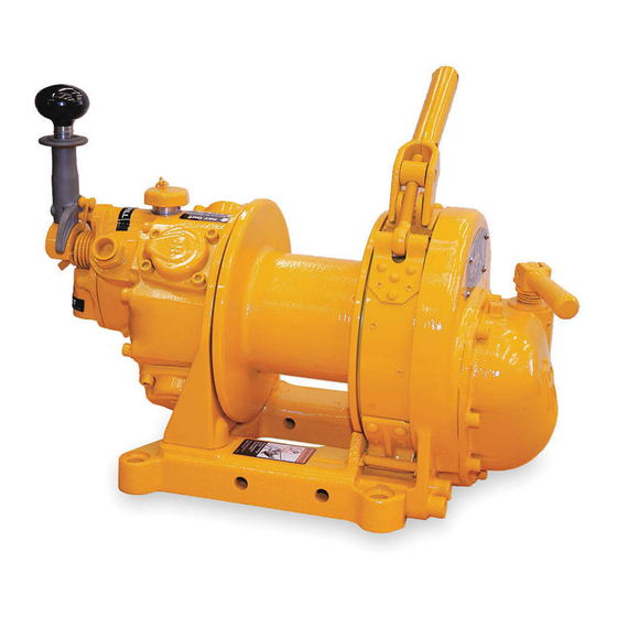
Ingersoll-Rand BU7A Parts, Operation And Maintenance Manual
Air winch
Hide thumbs
Also See for BU7A:
- Product information (13 pages) ,
- Product maintenance information (13 pages) ,
- Installation and operation manual (113 pages)
Table of Contents
Advertisement
PARTS, OPERATION AND MAINTENANCE MANUAL
(Dwg. MHP1233)
READ THIS MANUAL BEFORE USING THESE PRODUCTS. This manual
contains
information. Make this manual available to all persons responsible for the
operation, installation and maintenance of these products.
Do not use this Air Winch for lifting, supporting, or transporting people or lifting or
supporting loads over people.
Always operate, inspect and maintain this Air Winch in accordance with American
National Standards Institute safety code (ASME B30.7) and any other applicable safety
codes and regulations.
Form P5710
Edition 15
May 2001
03523115
© 2001 Ingersoll-Rand Company
MODEL BU7A AIR WINCH
important
safety,
for
installation,
operation
Form P5710
and
maintenance
Advertisement
Table of Contents

Subscribe to Our Youtube Channel
Related Manuals for Ingersoll-Rand BU7A


Summary of Contents for Ingersoll-Rand BU7A
- Page 1 Form P5710 PARTS, OPERATION AND MAINTENANCE MANUAL MODEL BU7A AIR WINCH (Dwg. MHP1233) READ THIS MANUAL BEFORE USING THESE PRODUCTS. This manual contains important safety, installation, operation maintenance information. Make this manual available to all persons responsible for the operation, installation and maintenance of these products.
-
Page 2: Table Of Contents
TABLE OF CONTENTS Description Page No. Safety Information Danger, Warning, Caution and Notice .................................3 Safety Summary........................................3 Safe Operating Instructions ....................................4 Warning Tags ........................................4 Specifications Description...........................................5 Model Code Explanation .....................................5 Performance Graphs ......................................6 Installation Mounting..........................................7 Wire Rope ..........................................7 Air Supply..........................................8 Initial Operating Checks ....................................10 Operation Winch Controls ........................................11 Winch Brakes ........................................11... -
Page 3: Safety Information
This is the customer’s responsibility. If in doubt, consult a registered structural engineer. Ingersoll-Rand cannot know of, or provide all the procedures by which product operations or repairs may be conducted and the hazards and/or results of each method. If operation or maintenance... -
Page 4: Safe Operating Instructions
10. Do not “side pull” or “yard”. 11. Make sure everyone is clear of the load path and there are no Ingersoll-Rand recognizes that most companies who use winches objects in the way of the load. Do not lift a load over people. -
Page 5: Specifications
SPECIFICATIONS Description The BU7A winch is powered by a radial piston air motor. The • The free spool feature must only be used with a manual output from the motor is transferred through the drum by the drive brake. Use of a manual brake is the only way to maintain shaft. -
Page 6: Performance Graphs
0.58 the factor corresponding to the operating pressure from 0.78 0.72 the table. 0.89 0.86 Example: Model BU7A at 750 lbs with 70 psi and drum half full. 1.00 1.00 To determine speed from curve: 1.11 1.14 50 fpm x 0.72 = 36 fpm. -
Page 7: Installation
INSTALLATION Prior to installing the winch, carefully inspect it for possible lubricated or a thread locking compound is used, torque to 80 shipping damage. ft lbs (11.0 kg m). Winches are supplied from the factory drained of oil. Add oil prior When a lead sheave is used, it must be aligned with the center to winch operation. -
Page 8: Air Supply
Refer to Table 1 on page 8 for minimum and maximum recommended wire rope diameters. Table 1 Minimum and Maximum Wire Rope Sizes Minimum Maximum Model inch inch BU7A 5/16 * Breaking Strength Weight Weight Rope Size (Dwg. MHP1288) per ft per metre (in.) - Page 9 Motor For optimum performance provide an air supply of 90 psig at 50 scfm (6.3 bar/630 kPa at 1.4 cu.m/min) for BU7A winches. The air motor should be installed as near as possible to the compressor or air receiver. Recommended pressures and volumes are measured at the point of entry to the air motor.
-
Page 10: Initial Operating Checks
Initial Operating Checks Winches are tested for proper operation prior to leaving the factory. Before the winch is placed into service the following initial operating checks should be performed. Refer to the “LUBRICATION” section to ensure correct oil level in air motor. When first running the motor, inject some light oil into the inlet connection to provide initial lubrication. -
Page 11: Operation
OPERATION The four most important aspects of winch operation are: Follow all safety instructions when operating the winch. Allow only people trained in safety and operation of this winch to operate this equipment. Subject each winch to a regular inspection and maintenance procedure. -
Page 12: Free Spool Clutch
brake band. When control valve is returned to neutral, there is no “EMERGENCY air supply to the brake cylinder so the internal spring will retract STOP” the brake rod causing the brake lever to lock the brake band in Button position. -
Page 13: Inspection
INSPECTION Inspection information is based in part on American National WINCH. Prior to operation, visually inspect winch housing, Standards Institute Safety Codes (ASME B30.7). control, brake and drum for indications of damage. Any discrepancies noted must be reviewed and inspected further by authorized personnel instructed in the operation, safety and maintenance of this winch. -
Page 14: Winches Not In Regular Use
all items listed in “Frequent Inspection.” Also inspect the DRUM GUARD (optional feature). Verify fasteners are tight following: and in good condition. Ensure guard is in good condition. FRAMES, CASES AND BRACKETS. Check for deformed, 10. EMERGENCY STOP VALVE (optional feature). During cracked or corroded main components. -
Page 15: Inspection And Maintenance Report
Refer to the Parts, Operation and Maintenance Manual “INSPECTION” section for general inspection criteria. Also, refer to appropriate National Standards and codes of practice. If in doubt about an existing condition, contact the nearest Ingersoll-Rand Distributor or the factory for technical assistance. -
Page 16: Lubrication
Refer to Table 3 on page 16. Brush, drip or spray lubricant weekly, or more frequently, Allow oil to settle before topping off. Oil capacity for the BU7A depending on severity of service. winch motor is 1/2 pint (0.24 litres). Pour sufficient oil into the vent cap opening to bring the oil in the motor case to the level of the upper oil plug hole. -
Page 17: Troubleshooting
TROUBLESHOOTING This section provides basic troubleshooting information. Determination of specific causes to problems are best identified by thorough inspections performed by personnel instructed in safety, operation and maintenance of this equipment. The chart below provides a brief guide to common winch symptoms, probable causes and remedies. Symptom Cause Remedy... -
Page 18: Maintenance
Proper use, inspections and maintenance increase the life and If drum rotates, remove brake lever, tighten trunnion usefulness of your Ingersoll-Rand equipment. During assembly, clockwise another half turn and test again. Repeat until drum lubricate gears, nuts, capscrews and all machined threads with does not rotate when lever is locked and throttle is activated. -
Page 19: Disassembly
Always inspect removed oil for evidence of internal damage The construction of the BU7A winch allows for the motor to be or contamination (metal shavings, dirt, water, etc.). If removed, repaired and replaced without removing the gears. - Page 20 Using a 7/16 in. -14 thread bolt, remove rotary valve (15) from rotary valve bushing (14). Unscrew eight motor case capscrews (29) and remove motor case (28) containing assembled motor from motor mounting bracket (79). Unscrew four cylinder capscrews (21) from any one of the four cylinder heads (23) and remove the cylinder head, cylinder sleeve (19) and gasket (24).
-
Page 21: Cleaning, Inspection And Repair
second one has a slot to clear the bushing key. Press old reverse valve bushing (12) out of motor housing (28). NOTE: This bushing is only 2 inches (51 mm) long. • The two drum bearings (84), one located at each end of the Measure motor housing bore, if greater than 1.313 in. -
Page 22: Assembly
35. Snug up the capscrews on opposite cylinder head. 36. Repeat this procedure for the other two cylinder heads. • Earlier BU7A winches contain a reverse valve bushing with 37. Repeat these steps until ALL cylinder heads are final the keyway running the entire length of bushing making it tightened. - Page 23 39. Match hole pattern in gasket (32) and motor mounting 12. Use bench to hold free end of spring. Then, twist throttle bracket. Press gasket into position. lever so that the stud goes past the free end of spring. 40. Place motor mounting bracket onto motor case. 13.
- Page 24 Slide drive gear (99), jaw side outward, onto drive shaft and Mount the brake cylinder to the brake cylinder mounting against bearing. bracket (139) by reinstalling the pin (138) and retainers Place a washer (97) over the drive shaft and secure with a (137).
-
Page 25: Testing
125% of the rated load at mid drum, apply the following load: BU7A winch 125% Test Load = 1250 lbs (567 kg). • Testing to more than 125% of rated line pull may be required to comply with standards and regulations set forth in areas outside the USA. -
Page 26: Winch Assembly Parts Drawing
WINCH ASSEMBLY PARTS DRAWING (Dwg. MHP1207) P5710 - Edition 15... -
Page 27: Winch Assembly Parts List
‘O’ Ring BU-948 Reverse Valve Assembly (incl’s items 1, 8 and 9) BU-9K44A Plug C6H20A-79 Reverse Valve Bushing Kit (incl’s Loctite® 609) BU7A-K945 (Model BU7APTAB only) BU7ARC-945 Rotary Valve Thrust Washer BU-552A Rotary Valve Bushing Kit (incl’s Loctite® 609) BU7A-K525... - Page 28 Clutch Eccentric Shaft (Manual brake models only) BU-857A • 48 ‘O’ Ring PS3-67 Bushing BU-964 Bushing (Model BU7APTAB only) BU7A-728 Brake Lever Screw 51014 • 51 Clutch Lever Spring (Manual brake models only) H02-81C Clutch Lever Washer (Manual brake models only) BU-962...
-
Page 29: Kits, Special Tools And Accessories
Piston Ring Compressor to compress Piston Rings (16) on Cylinder (19) D01-933 Wire Rope Lubricant, 13 oz. spray can LUBRI-LINK-GREEN Brake Lining Repair Kit BU-K155 Drum Guard Kit BU7A-K298A Air Strainer, 3/4 in. NPT EU-A267 Lubricator, 3/4 in. NPT L30-06-000 Filter, 3/4 in. NPT F30-06-000... -
Page 30: Automatic Brake Assembly Drawings And Parts List
AUTOMATIC BRAKE ASSEMBLY DRAWING 1 4 1 10 1 (Dwg. MHP1210) P5710 - Edition 15... - Page 31 Of Part Total Number Screw J-376 Brake Trunnion BU-159 Lockwasher 50181 Bearing TB-394 Brake Lever (incl’s items 56 and 131) BU7A-718 Capscrew 51014 UWB-1569 Cotter Pin 53456 Exhaust Elbow HUS-912 Brake Cylinder BU7A-720 Retainer Included with Item 138 Brake Cylinder Mounting Bracket...
-
Page 32: Shuttle Valve Chest Assembly Drawing
SHUTTLE VALVE CHEST ASSEMBLY DRAWING (Dwg. MHP1209) P5710 - Edition 15... -
Page 33: Shuttle Valve Chest Assembly Parts List
SHUTTLE VALVE CHEST ASSEMBLY PARTS LIST Item Description Part Of Part Total Number Washer BU-552A Shuttle Valve Chest Assembly (incl’s items 200 through 216) BU7A-A245 Shuttle Valve Chest BU7A-245 Brake Valve Bushing D01-63 Shuttle Valve Bushing 26069 Pipe Plug 502-95 Air Inlet Plug (shipping only) -
Page 34: Remote Control Stop Valve Assembly Drawing
REMOTE CONTROL VALVE ASSEMBLY PARTS DRAWING Use Loctite 609 Ref. MHD56154 for Installation procedures. (Dwg. MHP2221) P5710 - Edition 15... -
Page 35: Drum Guard Assembly Drawing And Parts List
Description Part Of Part Total Number Washer BU-552A Pendant Assembly (refer to Dwg. MHP1072 on page 38) MR-269C Shuttle Valve Chest Assembly BU7A-A245 Valve Chest Gasket BU7A-547 Ported Plug BU7ARC-945 Fitting, Connector 71009815 Hose (bulk) As Req’d 53245 Fitting, Hose End... -
Page 36: Stop Valve And Muffler Assembly Drawings And Parts Lists
E-STOP VALVE AND MUFFLER ASSEMBLY DRAWINGS (Dwg. MHP2222) P5710 - Edition 15... - Page 37 E-STOP VALVE AND MUFFLER ASSEMBLY PARTS LISTS Item Description Part Of Part Total Number Muffler 52104 Fitting, Adapter 71386924 Fitting, Nipple AAM-287 Stop Valve 76170017 Fitting, Elbow Reducer 71386916 P5710 - Edition 15...
-
Page 38: Remote Pendant Throttle Handle Drawing And Parts List
REMOTE PENDANT THROTTLE HANDLE DRAWING AND PARTS LIST Yellow Payout Supply Green Haul-in Payout Haul-in (Dwg. MHP1072) Item Description Part Of Part Total Number Pendant Assembly (incl’s all items below) MR-269C Throttle Lever MR-273 Throttle Lever Pin DLC-120A Screw MLK-SR662 Lockwasher D02-138 Bushing... -
Page 39: Label Locations Drawing And Parts List
LABEL LOCATIONS DRAWING AND PARTS LIST Ingersoll-Rand Co. 2724 6th Ave. So. Seattle, WA 98134 Ingersoll-Rand Co. 111, avenue Roger Salengro, 59450 Sin Le Nobel, France (Dwg. MHP2223) Part Number Item Description Of Part Total Standard -E Version Nameplate (illustrated on page 42) -
Page 40: Construction Cage Drawing And Parts List
CONSTRUCTION CAGE DRAWING AND PARTS LIST (Dwg. MHP2279) Item Description Part Of Part Total Number Cage 27398G Capscrew 51876 Washer 71064844 Lockwasher 50181 50171 Label, Specifications 71359210 Plexiglass Cover 27427 Screw 50851 50852 Label, Warning 71359160 Nameplate 71359392 Rivet 71028849 P5710 - Edition 15... -
Page 41: Winch Upgrades
BU7A-A516 Crankshaft Assembly On BU7A winches crankshaft BU7A-A516 has been redesigned to include the pinion as part of the shaft. The pinion is now machined as an integral part of the crankshaft, thus eliminating the old style crankshaft, motor pinion (BU-319), lockwasher (F-58) and motor pinion screw (BU-20). -
Page 42: Parts Ordering Information
PARTS ORDERING INFORMATION The BU7A winch is designed and constructed to provide long, trouble-free service. In time it may become necessary to order and install new parts to replace those that have been subjected to wear. • Continuing improvement and advancement of design may... -
Page 43: Warranty
WARRANTY LIMITED WARRANTY Ingersoll-Rand Company (I-R) warrants to the original user its I-R makes no other warranty, and all implied warranties Hoists and Winches (Products) to be free of defects in material including any warranty of merchantability or fitness for a... - Page 44 1200 Cliveden Avenue Chicago, IL world. Contact the nearest Delta, B.C. Ingersoll-Rand 131 W. Diversey Avenue Ingersoll-Rand office for the V3M 6G4 Distribution Center Elmhurst, IL 60126-1102 name and address of the Phone: (604) 523-0803 P.O. Box 618...
Need help?
Do you have a question about the BU7A and is the answer not in the manual?
Questions and answers