Table of Contents
Advertisement
Quick Links
Advertisement
Table of Contents

Subscribe to Our Youtube Channel
Related Manuals for Ingersoll-Rand Man Rider LS2-150HLP Series


Summary of Contents for Ingersoll-Rand Man Rider LS2-150HLP Series
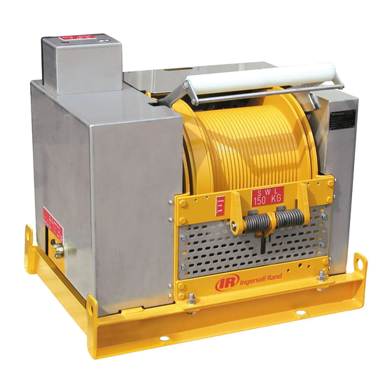
- Page 1 Product Maintenance Information Hydraulic Man Rider™ Winch LS2-150HLP Series Models LS2-150HLP-L()-E LS2-150HLP-PHXXM-()-E (Lever Control) (Remote Control) (Dwg. MHP2876) Save These Instructions Form MHD56364 Edition 1 June 2009 43802123 © 2009 Ingersoll-Rand Company...
-
Page 2: Periodic Inspection
Only allow Ingersoll Rand trained technicians to perform maintenance on this Product. For additional information contact Ingersoll Rand factory or nearest Distributor. For additional supporting documentation refer to Table 1, ’Product Information Manuals,’ on page 2. Manuals can be downloaded from www.ingersollrandproducts.com. The use of other than genuine Ingersoll Rand replacement parts may result safety hazards, decreased performance and increased maintenance and may invalidate all warranties. - Page 3 Table 3: Maintenance Interval Chart Normal Application The following work can be completed by owner maintenance personnel System Hydraulic Filter Inspect system hydraulic filter every 45 days or 150 hours. Grease Fittings Lubricate grease fittings every 180 days or 500 hours. It is recommended that the following work be completed by an Ingersoll Rand trained technician.
-
Page 4: Inspection Report
INSPECTION REPORT Ingersoll Rand Model LS2-150HLP Hydraulic Winch Model Number: Date: Serial Number: Inspected by: Reason for Inspection: (Check Applicable Box) 1. Scheduled Periodic Inspection: (_____ Quarterly _____ Semiannually _____ Yearly) Operating Environment: 2. Discrepancy(s) noted during Frequent Inspection Normal: ___ Heavy: ___ Severe: ___ 3. -
Page 5: Troubleshooting
TROUBLESHOOTING This section provides basic troubleshooting information. Determination of specific causes to problems are best identified by thorough inspections performed by Ingersoll Rand trained technicians. The chart below provides a brief guide to common winch symptoms, probable causes and remedies. SYMPTOM CAUSE REMEDY... -
Page 6: Maintenance
MAINTENANCE WARNING • Never perform maintenance on the winch while it is supporting a load. • Before performing maintenance, tag controls: WARNING - DO NOT OPERATE - EQUIPMENT BEING REPAIRED. • Only allow Ingersoll Rand trained technicians to perform maintenance on this product. - Page 7 Overload Device Cleanliness Refer to Dwg. MHP2330 on page 7, A. Adjust Torque Limiter Valve to Limit Winch Lift Keep equipment clean. A thick layer of dirt acts as insulation, causing the hydraulic Capacity to 125% of the SWL. system to retain heat resulting in higher operating temperatures. If the system is opened for inspection or repair, a clean work area prevents foreign CAUTION contaminants from entering the system and damaging component internal parts.
- Page 8 6. When grasping a part in a vise, always use leather-covered or copper-covered Winch Disassembly vise jaws to protect the surface of the part and help prevent distortion. This is particularly true of threaded members, machined surfaces and housings. Refer to Dwgs. MHP2643, MHP2844 and MHP2845. 7.
-
Page 9: Cleaning, Inspection And Repair
Cleaning, Inspection and Repair Planet Gear Support Cleaning CAUTION • A bearing that appears loose or does not rotate smoothly must be replaced. Failure to observe this precaution will result in bearing and/or winch component damage. Clean all winch component parts in solvent (except for the brake friction discs). The use of a stiff bristle brush will facilitate the removal of accumulated dirt and sediments in the drum and reduction assembly. -
Page 10: Operational Tests
15. Install ‘ON - OFF’ valve (398) on spacer (387) with capscrews (96) and 12. Install belt (367) around wheel and driving pulley. lockwashers (397). 13. Install belt tensioning roller (364) with capsrew (360) on roller support (368). Adjust tensioning roller (364) to remove slack from belt (367). Automatic Band Brake Assembly 14. -
Page 11: Torque Chart
TORQUE CHART Standard Coarse Thread Torque SAE Grade 5 SAE Grade 8 Size Lubricated PTFE Lubricated PTFE 1/4-20 8-10 12-14 9-10 5/16-18 17-20 13-15 25-28 18-21 11-13 3/8-16 31-35 23-26 14-16 44-49 33-37 20-22 7/16-14 49-56 37-42 22-25 70-79 52-59 31-36 1/2-13 75-85... - Page 12 www.ingersollrandproducts.com...
Need help?
Do you have a question about the Man Rider LS2-150HLP Series and is the answer not in the manual?
Questions and answers