Table of Contents
Advertisement
Quick Links
Advertisement
Table of Contents

Related Manuals for TRI tool BEVELMASTER 204B-DC


Summary of Contents for TRI tool BEVELMASTER 204B-DC
- Page 1 Operation Manual...
- Page 2 ABOUT TRI TOOL TECHNOLOGIES At Tri Tool, we are committed to your success through relentless innovation and powerful partnership. We insist on developing tools and equipment that exceed your expectations of performance, precision, safety, and durability. As a full-service engineering firm, we are here to support you every step of the way.
-
Page 3: Table Of Contents
TABLE OF CONTENTS Tri Tool Inc Warranty Tool Bit Resharpening Policy About the Manual Safety General Description Specifications Maintenance 18 Operation Machining Operation Cutting Speeds and Feeds Jaw Blocks and Ramp Sets Surefire 4 Pad Kits 30 Tool Bits Troubleshooting Accessories Illustrated Parts Breakdown 38... -
Page 4: Tri Tool Inc Warranty
TRI TOOL INC. TRI TOOL INC. Warranty LIMITED WARRANTY: All products manufactured by Seller are warranted to be free from defects in materials and workmanship under normal use. The period of this warranty shall be three (3) years from the date of shipment for all products, except for welding and Non-Standard Products which shall be one year from the date of shipment. -
Page 5: Tool Bit Resharpening Policy
Model 204B BEVELMASTER™ that the defect was discovered during the warranty period. No warranty claims submitted after this fifteen (15) day calendar period will be considered by Seller. Buyer’s notice of a defective Goods must identify the specific Goods affected, and the nature of the defect. It is required when returning the defective Goods, that it is suitably packed, fully insured, and transportation and insurance prepaid in accordance with instructions issued by Seller. -
Page 6: About The Manual
The instructions and descriptions in this manual were accurate when the manual was written. However, the information in the manual is subject to change without notice. Check for updated information before you start any job. The Tri Tool Inc. web site has the most current information. -
Page 7: Safety
Model 204B BEVELMASTER™ 2. SAFETY PRECAUTIONS In General Use standard safety equipment such as: hard hats, safety shoes, safety harnesses, protective clothes, and other safety devices when appropriate. Operate this tool only in accordance with specific operating instructions. WARNING: Do not override the dead-man switch on the power unit. Locking down, obstructing, or in any way defeating the dead-man switch on the power drive unit may result in serious injury. - Page 8 Before you start operating the equipment, do no-load tests and feed function checks. Tool Use Use the right tool and tool bit for the job. Contact Tri Tool to help with your application. Keep the tool bits fully engaged in the tool bit holders. Loose bits are sharp and can cause cuts or punctures.
-
Page 9: General Description
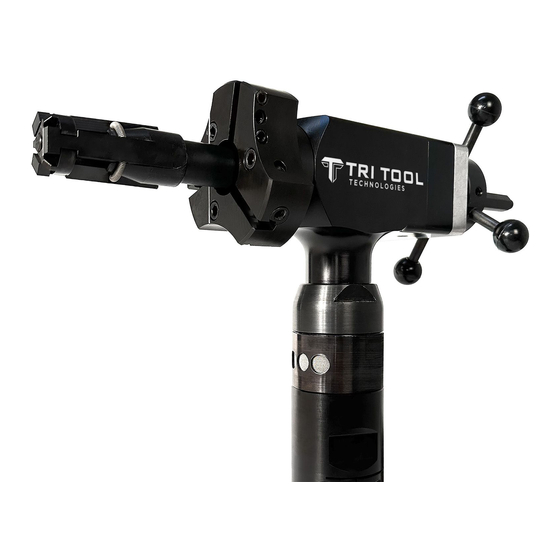
Model 204B BEVELMASTER™ 3. GENERAL DESCRIPTION The Model 204B BEVELMASTER™ is a Pipe Beveler designed for facing, beveling and/or counterboring the ends of pipe or tubing in preparation for welding. These machining operations may be performed either simultaneously or separately. Pipe weld end preparations that meet all existing conventional codes including the more stringent nuclear codes may be machined. -
Page 10: Specifications
TRI TOOL INC. 4. SPECIFICATIONS MODEL 204B BEVELMASTER™ with AIR MOTOR Weight 18 lbs (8.1 kg) Power Requirements 55 cfm at 90 psi (26 L/s at 621 kPn) 16.42" (417.1 mm) 4.00" 8.97" (101.6 mm) (227.8 mm) 7.18" (182.4 mm) Mandrel Cutting Head (Travel 1.5"... - Page 11 Mild steels, Chrome steels (Rc 35 max), stainless steel, copper-nickel alloys and aluminum without limitations except size and wall thickness as specified in paragraph #2. Inconel and other high temperature alloys may require special procedures as a function of wall thickness and type of end preparation. Contact Tri Tool’s Engineering Department for details. Clearance and Dimensions Rotating Head DIA.
- Page 12 TRI TOOL INC. Drive System Final Drive Gear Driven Pneumatic Motor Free speed 325 rpm Max. H.P. speed 162 rpm Power Supply Pneumatic motor requires 55 cfm (26 L/s) air supply at 90 psi (621 kPa) for maximum horsepower delivery.
- Page 13 Model 204B BEVELMASTER™ MODEL 204B BEVELMASTER™ with ELECTRIC MOTOR Weight 18 lbs (8.1 kg) Power Requirements 115 VAC, 28 to 60 Hz 9.6 amp 16.57" (420.88 mm) 4.00" 8.79" (101.60 mm) (223.27 mm) 7.03" (178.56 mm) Mandrel In-line Feed 20.25" (514.35 mm) Cutting Head (Travel 1.5" maximum) Figure 2: Envelope Drawing 92-0699 Rev. 240212...
- Page 14 TRI TOOL INC. Pipe Cutting Capacities Basic Pipe Sizes 1” Pipe Schedule 40 (Small Mandrel required to mount in 1” schedule 80 and above.) 1 1/4” through 2 1/2” Pipe Up to Schedule 160 * Some Schedules may require optional equipment. Basic Tube Sizes Up to .250” (6.4 mm) wall tubing with a maximum OD of 4.50” (114.3 mm) and a minimum ID of 1.25”...
- Page 15 Mild steels, chrome steels, (Rc 35 max), stainless steel, copper-nickel alloys and aluminum without limitations except size and wall thickness as specified in the above paragraphs. Inconel and some other high temperature alloys may require special procedures as a function of wall thickness and type of end preparations. Contact Tri Tool’s Engineering Department for details. Clearance and Dimensions Rotating Head DIA.
- Page 16 TRI TOOL INC. Power Supply 115 VAC, 9.6 Amps, 28 to 60 Hz. Cutting Head Speeds Max. Cutting Head Speed Low Range 84 rpm High Range 156 rpm Cutting Head Speed @ Max. H.P. Low Range 56 rpm High Range 105 rpm Functional Speed Range 20 to 100 rpm Speed Control On/Off Trigger control with Variable Speed.
- Page 17 Model 204B BEVELMASTER™ MODEL 204DC with CORDLESS MOTOR Weight 25 lbs (11.3 kg) Power Requirements 204DC 110V 110 VAC, 50/60 Hz 204DC 220C 220 VAC, 50/60 Hz 4.00in 101.6mm ROTATING DIA 16.39in 416.3mm 8.83in 224.2mm 7.03in 178.4mm Mandrel 17.03in Cutting Head 432.5mm (Travel 1.50"...
- Page 18 Mild steels, chrome steels, (Rc 35 max), stainless steel, copper-nickel alloys and aluminum without limitations except size and wall thickness as specified. Inconel and some other high temperature alloys may require special procedures as a function of wall thickness and type of end preparations. Contact Tri Tool’s Engineering Department for details. Drive System Final Drive Gear Driven...
- Page 19 Model 204B BEVELMASTER™ Speed Control Variable Speed Trigger Mounting Manually actuated draw rod expands mandrel ramps and jaw blocks. Feed Manual-Feed Handle is in line at the back of the machine. Feed rate is .100” (2.5mm) per revolution of the feed handle. Maximum available feed travel is 1.50” (38.1 mm) 92-0699 Rev.
-
Page 20: Maintenance
Verify that there is adequate grease in the gear box. Gears and bearings are to be lubricated using a lithium based grease. Disassembly of a power unit voids warranty, except when performed by a TRI TOOL INC. designated repair technician. A letter of designation is required. - Page 21 Model 204B BEVELMASTER™ Grease Port Air Motor Lubrication No direct maintenance is normally required on the air motor. However, the air supply must flow through a filter/regulator/lubricator (FRL) unit or separate units before arriving at the air motor. The FRL unit must be maintained as required, frequency dependent on the basic air supply, to keep the water trap drained, filter cleaned and the lubricator oil reservoir filled so that a drop of oil every two (2) to five (5) seconds is flowing.
-
Page 22: Operation
TRI TOOL INC. 6. OPERATION General Comments Read the operating instructions carefully before attempting to operate the Model 204B BEVELMASTER™ Use eye protection at all times when operating the Model 204B BEVELMASTER™ Installation Select the recommended jaw blocks for the pipe size to be machined. - Page 23 Model 204B BEVELMASTER™ Final Prep Draw Nut SUREFIRE Location Pads Pipe Mandrel Assembly Figure 4: Tool installation NOTE: In order to avoid cutting the ramps and/or jaw blocks during the machining operation, the mandrel must be installed beyond the final preparation location. Tighten the draw nut to force the jaw blocks out to the inside diameter of the pipe or tube.
- Page 24 WARNING: Use of dull or improperly designed tool bits or tool bits not manufactured by Tri Tool Inc. may result in poor performance and may constitute abuse of the ma- chine and therefore voids the Tri Tool Inc. factory warranty.
-
Page 25: Machining Operation
Model 204B BEVELMASTER™ 7. MACHINING OPERATION Tool Bit Cutting Edge Set Screws Rotation Depress the air motor trigger. Adjust the cutting speed by rotating the flow valve at the air connection. Rotate the feed handle clockwise to bring the tool bit(s) and pipe closer together. WARNING: Do not override the dead-man switch on this unit. Locking down, obstruct- ing, or in any way defeating the dead-man switch on this unit may result in serious injury. - Page 26 TRI TOOL INC. When the pipe end is not square to the pipe axis, the Tool Bit will contact only a small segment of the pipe during each revolution. To avoid tool bit damage, the feed rate should be very slow until the tool bit(s) is in contact with the pipe continually during at least one full revolution.
-
Page 27: Cutting Speeds And Feeds
Model 204B BEVELMASTER™ 8. CUTTING SPEEDS AND FEEDS Use 200 surface inches per minute (5080 surface millimeters per minute) for: Stainless steels in general when no coolant is allowed, all heavy-wall tube and some chrome/molybdenum steels. Use 250 surface inches per minute (6350 surface millimeters per minute) for: Mild steels and some thin-wall stainless steels when coolants are permitted and applied. -
Page 28: Jaw Blocks And Ramp Sets
TRI TOOL INC. 9. JAW BLOCKS AND RAMP SETS STEEL JAW BLOCKS AND RAMPS Ramp Block Mandrel Assembly Used with Mandrel Assembly (P/N 06-0419) 92-0699 Rev. 240212... - Page 29 Model 204B BEVELMASTER™ STEEL JAW BLOCK AND RAMP PROFILES - STANDARD MANDREL Mounting ID Ramp and Block Combination 1.250" to 1.630" (31.8 mm to 41.4 mm) 1.560" to 2.000" (39.6 mm to 50.8 mm) 1.930" to 2.390" (49.0 mm to 60.7 mm) 2.320" to 2.780" (58.9 mm to 70.6 mm) 2.710" to 3.160" (68.8 mm to 80.3 mm) 3.090"...
- Page 30 TRI TOOL INC. STEEL JAW BLOCK AND RAMP PROFILES - STANDARD MANDREL Mounting ID Ramp and Block Combination 3.480" to 3.940" (88.4 mm to 100.1 mm) 3.870" to 4.330" (98.3 mm to 110.0 mm) 92-0699 Rev. 240212...
- Page 31 Model 204B BEVELMASTER™ BUTT PLATE, SPRING AND RAMP Butt Plate Mandrel Sleeve Ramp Mandrel Assembly Spring Used with Mandrel Assembly (P/N 06-0413) BUTT PLATE, SPRING AND RAMP Ramp Mandrel Assembly Spring Used with Mandrel Assembly (P/N 06-0414) 92-0699 Rev. 240212...
-
Page 32: Surefire 4 Pad Kits
TRI TOOL INC. 10. SUREFIRE 4 PAD KITS 2"-2 1/2" Pipe 3"- 4" Pipe Pipe ID SUREFIRE Kit P/N Figure: 17. Full Support Pad Assembly 2" SCH5S 05-1610 2" SCH10S 05-1611 2 1/2" SCH5S 05-1612 2 1/2" SCH10S 05-1613 3" SCH5S 05-1614 3"... - Page 33 Model 204B BEVELMASTER™ Mandrel Assembly Pad Kit Ramp Block Figure 6: Pad Assembly 05-1610 through 05-1613 Fig 8: Pad Assembly 05-1610 through 05-1613 Pad Kit Mandrel Assembly Ramp Block Figure 7: Pad Assembly 05-1614 through 05-1617 92-0699 Rev. 240212...
-
Page 34: Tool Bits
TRI TOOL INC. 11. TOOL BITS TOOL BIT, 37.5° BEVELING Pipe Cutting Head Cutting Edge Tool But, Beveling Pipe 37.5° Max. Beveling Range Wall Tube Tool Bit Thickness Material 1 1/4” ID thru 3” pipe .531” (13.5 mm) Durabit 7 (31.8 mm ID thru 88.9 mm OD) - Page 35 Model 204B BEVELMASTER™ TOOL BIT, BEVELING AND FACING Facing Tool Bit Pipe Cutting Head Cutting Edge Tool Bit, Beveling 92-0699 Rev. 240212...
- Page 36 TRI TOOL INC. TOOL BIT, FACING (LAND) Pipe Cutting Head Cutting Edge Tool Bit, Facing (Land) 92-0699 Rev. 240212...
- Page 37 Model 204B BEVELMASTER™ TOOL BIT, ID CHAMFER Pipe Cutting Head Cutting Edge Tool Bit, ID Chamfer 92-0699 Rev. 240212...
-
Page 38: Troubleshooting
TRI TOOL INC. 12. TROUBLESHOOTING Problem: The Tool Bit Chatters The tool bit is loose or overextended. The tool bit is damaged. The tool holder is too loose in the slides. The cutting speed is too fast. The clamping pads are loose on the pipe or tube. -
Page 39: Accessories
8. Pointer Kit, Elbow Mandrel 204B (P/N 05-0316) 9. Indicator Kit, Dial (P/N 05-0317) 10. Adjustable Pin Kit, Elbow Mandrel (P/N 05-0355) 11. Kit, SUREFIRE 4 Pads (P/N 05-1610 - 05-1617) 12. Pipe Wrench, 12 In, Smooth Jaw, 2-5/8 (P/N 36-0755)* *NOTE: Above wrench is recommended for removal of pneumatic motor A portable Air Caddy (FRL) is required to protect the warranty on all Tri Tool Inc. air driven tools. 92-0699 Rev. 240212... -
Page 40: Illustrated Parts Breakdown
TRI TOOL INC. 14. ILLUSTRATED PARTS BREAKDOWN MODEL 204B BEVELMASTER™ SUB-ASSEMBLY (P/N 02-3173) QTY. 92-0699 Rev. 240212... - Page 41 Model 204B BEVELMASTER™ MODEL 204B BEVELMASTER™ SUB-ASSEMBLY (P/N 02-3173) Con't 92-0699 Rev. 240212...
- Page 42 TRI TOOL INC. Parts List, Model 204B BEVELMASTER™ Sub-Assembly (P/N 02-3173) Item Part Description 19-0729 HOUSING,FEED 2. 19-1962 HOUSING,MAIN BLACK 20-1025 SHAFT,MAIN 4. 27-1686 ADAPTOR, FEED BLACK 5. 28-0248 O-RING,2-1/4 ID X 3/32 6. 29-0005 BRG,BALL,1-9/16 X 2-5/16X 7/16 7. 29-0326 BRG,BALL,.5906 X 1.378 X .433 8. 29-0327 BRG,BALL.9843 X 1.850 X .4724 9. 29-0328 BRG,TAPER CONE,1-1/4” ID X .660” 10.
- Page 43 Model 204B BEVELMASTER™ Parts List, Model 204B BEVELMASTER™ Sub-Assembly (P/N 02-3173) Item Part Description 39-0754 GEAR,BEVEL,10DP,11T,1.10PD 39-0755 GEAR,BEVEL,10DP,22T,2.20DP 28. 40-0227 SPRING,WAVE 41-0136 HANDLE ASSY, IN-LINE FEED,204B 30. 45-0248 BUSHING,FEED ADAPTOR 54-0375 FITTING, GREASE NOT SHOWN 05-1327 WRENCH KIT, 204B 36-0004 WRENCH, L, 7/64" HEX 36-0006 WRENCH, L, 9/64" HEX 36-0007 WRENCH, L, 5/32" HEX 36-0010...
- Page 44 TRI TOOL INC. MOTOR ASSEMBLY, AIR (P/N 57-0224) Parts List, Motor Assembly, Air (P/N 57-0224) Item Part Description 53-0046 VALVE, FLOW CONTROL 2. 54-0126 COUPLING, MALE QD 54-0201 CAP, YELLOW 57-0223 MOTOR, INLINE AIR 92-0699 Rev. 240212...
- Page 45 Model 204B BEVELMASTER™ ELECTRIC MOTOR ASSEMBLY, 110V, 220V (P/N 58-0147, 58-0133) Parts List, Electric Motor Assembly, 110V, 220V (P/N 58-0147, 58-0133) Item Part Description 27-0357 ADAPTOR, MOTOR 2. 2 9-0182 BRG,BALL,1/2 X 1-1/8 X 3/8 3. 3 0-0508 LABEL,”WARNING,DISCONNECT” 30-0961 LABEL,WARNING,SAFETY SWITCH 5. 3 3-0039 SCREW,CAP,1/4-20 X 5/8 6. 39-0568 GEAR, DRIVE 44-0411 SPACER 8. 5 8-0277 MOTOR,C.W.ELEC,METABO,110V 58-0323 MOTOR, MOD., ELECTRIC, 220V...
- Page 46 TRI TOOL INC. ELECTRIC MOTOR ASSEMBLY, 110V, 220V (P/N 58-0422, 58-0436) Parts List, Electric Motor Assembly, 110V, 220V (P/N 58-0422, 58-0436) Item Part Description 27-1707 ADAPTOR,MOTOR 2. 2 9-0182 BRG,BALL,1/2 X 1-1/8 X 3/8 30-6136 LABEL,POWER DISCONNECT & SAFETY SWITCH 4. 3 3-0055 SCREW, CAP ( 5/16-18 x .88 ) 5. 3 9-0568 GEAR, DRIVE 44-0441 SPACER 7. 5 8-0317...
- Page 47 Model 204B BEVELMASTER™ CUTTING HEAD KIT, 4" DIA (P/N 03-0049) Parts List, Cutting Head Kit, 4" DIA (P/N 03-0049) Item Part Description 21-0475 HEAD, 4.0" DIA 2. 28-0249 SEAL, OIL 3. 33-0057 SCREW, CAP, 5/16-18 X 1 1/4" 4. 33-0514 SCREW, SET, 5/16-18 X 3/8", CUP PT 5. 33-0517 SCREW, SET, 5/16-18 X 5/8", CUP PT 6. 33-0518 SCREW, SET, 5/16-18 X 3/4", CUP PT 7. 33-0996 SCREW, SET, 5/16-18 X 1/2", HDOG 8. 62-0104 CAM, FACING BIT 92-0699 Rev. 240212...
- Page 48 TRI TOOL INC. MANDREL ASSEMBLY (P/N 06-0413) Parts List, Mandrel Assembly (P/N 06-0413) Item Part Description 13-0429 MANDREL 2. 23-0298 ROD, DRAW 24-1463 PLATE, BUTT #1 24-1464 PLATE, BUTT #2 4. 33-0477 SCREW, SET, #8-32 X 3/16", CUP PT 33-0478 SCREW, SET, #8-32 X 1/4", CUP PT 5. 35-0523 NUT, DRAW ROD, 3/8-16 40-0130 SPRING, FLAT...
- Page 49 Model 204B BEVELMASTER™ MANDREL ASSEMBLY (P/N 06-0414) Parts List, Mandrel Assembly (P/N 06-0414) Item Part Description 13-0426 MANDREL 23-0297 ROD, DRAW 24-1462 PLATE, BUTT 4. 33-0489 SCREW, SET, #10-24 X 5/16", CUP PT 5. 35-0523 NUT, DRAW ROD, 3/8-16 6. 40-0108 SPRING, EXTENSION 7. 48-0976 BLOCK, RAMP 92-0699 Rev. 240212...
- Page 50 TRI TOOL INC. MANDREL ASSEMBLY (P/N 06-0419) Parts List, Mandrel Assembly (P/N 06-0419) Item Part Description 08-XXXX BLOCK, JAW (Ref. the ‘Jaw Blocks’ section.) 13-0424 MANDREL 23-0295 ROD, DRAW 4. 24-1384 PLATE, BUTT 5. 33-0490 SCREW, SET, #10-24 X 3/8", CUP PT 6. 35-0523 NUT, DRAW ROD, 3/8-16 7. 40-0001 SPRING, EXTENSION 8. 48-0964 BLOCK, RAMP, #1 48-0965 BLOCK, RAMP, #2...
- Page 51 67-5757 PAD, FULL SUPPORT, 204B, 2 1/2"SCH5S Model 204B BEVELMASTER™ KIT, SUREFIRE 4 PADS (P/N 05-1610 - 05-1613) KIT, SUREFIRE 4 PADS (P/N 05-1610 & 05-1611) Item Part Description 33-5056 SCREW, ULTRA LOW, 10-24 X 1/2” 67-5757 PAD, FULL SUPPORT, SUREFIRE 4, 2” SCH5S 67-5758 PAD, FULL SUPPORT, SUREFIRE 4, 2” SCH10S KIT, SUREFIRE 4 PADS (P/N 05-1612 &...
- Page 52 TRI TOOL INC. KIT, SUREFIRE 4 PADS (P/N 05-1614 & 05-1615) KIT, SUREFIRE 4 PADS, (P/N 05-1614 & 05-1615) Item Part Description 33-0027 SCREW, CAP, 10-24 X 3/8 33-0029 SCREW, CAP, 10-24 X 5/8 48-4686 BLOCK, EXTENSION, SUREFIRE 4 67-5761 PAD, FULL SUPPORT, SUREFIRE 4, 3” SCH5S 67-5762 PAD, FULL SUPPORT, SUREFIRE 4, 3” SCH10S 92-0699 Rev. 240212...
- Page 53 QTY. ITEM NO. PART NUMBER DESCRIPTION 33-5056 Ultra-Low-Profile Socket Head Screw Model 204B BEVELMASTER™ 67-5757 PAD, FULL SUPPORT, 204B, 2 1/2"SCH5S KIT, SUREFIRE 4 PADS (P/N 05-1616 & 05-1617) KIT, SUREFIRE 4 PADS, (P/N 05-1616 & 05-1617) Item Part Description 33-0027 SCREW, CAP, 10-24 X 3/8 33-0029 SCREW, CAP, 10-24 X 5/8 34-0252 WASHER, NYLON,.370” OD X .192” ID 48-4686 BLOCK, EXTENSION, SUREFIRE 4 67-5763 PAD, FULL SUPPORT, SUREFIRE 4, 4”...
- Page 55 • Disconnect power sources before servicing or moving the equipment. • Remove all loose articles of clothing and jewelry before operating the equipment. Be Safety Conscious! 3041 Sunrise Blvd. Rancho Cordova, CA 95742 +1(916) 288-6100 • +1(800) 345-5015 www.tritool.com ©Copyright Tri Tool Inc. PN 81-0542 (04-21)
Need help?
Do you have a question about the BEVELMASTER 204B-DC and is the answer not in the manual?
Questions and answers