
Related Manuals for TRI tool BEVELMASTER 214B


Summary of Contents for TRI tool BEVELMASTER 214B
-
Page 1: Table Of Contents
TABLE OF CONTENTS CUSTOMER MESSAGE Inside Front Cover SAFETY PRECAUTIONS GENERAL DESCRIPTION SPECIFICATIONS SETUP AND OPERATION CUTTING SPEEDS AND FEEDS TOOL BITS JAW BLOCKS, RAMPS AND ADAPTERS MAINTENANCE TROUBLESHOOTING ACCESSORIES ILLUSTRATED PARTS BREAKDOWN TOOL BIT RESHARPENING POLICY Inside Back Cover WARRANTY INFORMATION Inside Back Cover... - Page 2 Copyright 2014 Proprietary property of TRI TOOL INC. No reproduction, use, or duplication of the information shown hereon is permitted without the express written consent of TRI TOOL INC.
-
Page 3: Safety Precautions
Model 214B BEVELMASTER ® SAFETY PRECAUTIONS IN GENERAL When using rotating head cutting equipment, follow the safety recommendations in this manual to reduce the risk of personal injury. Operate this tool only in accordance with specific operating instructions. Do not override the deadman switch on the power unit. Locking down, ob- WARNING: structing, or in any way defeating the deadman switch on the power drive unit may result in serious injury. - Page 4 TRI TOOL INC. TOOL CARE Maintain tools with care. Keep tools in good operating condition. Sharp tool bits perform better and safer than dull tool bits. Well maintained tools function properly when needed. Check for damaged parts. If a tool has malfunctioned, been dropped or hit, it must be checked for damage.
- Page 5 Model 214B BEVELMASTER ® Remove adjusting keys and wrenches before applying power to the equipment. De- velop a habit of checking the tool before turning it on to make sure that all keys and wrenches have been removed. Do not force tools. Tools and tool bits function better and safer when used at the feed and speed rate for which they were designed.
-
Page 6: General Description
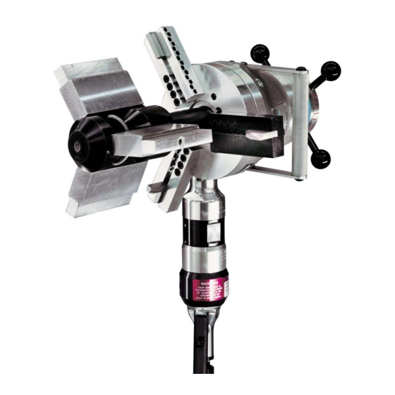
TRI TOOL INC. GENERAL DESCRIPTION The Model 214B BEVELMASTER® is a portable ID mount machine tool for beveling, facing and counterboring 4" (101.6 mm) through 14" (355.6 mm) pipe. The tool is configured with an in-line feed knob and has the option for a pneumatic, electric 115V/230V heavy duty and/or hydraulic drive motor positioned in a right angle to the lathe head. -
Page 7: Specifications
Model 214B BEVELMASTER ® SPECIFICATIONS DESIGN AND OPERATING FEATURES The lathe accepts its own torque through the mandrel. The expanding mandrel provides fast, accurate self-centering and alignment. The lathe, provided with a convenient handle, is lightweight and easily handled by one operator. - Page 8 TRI TOOL INC. MODEL 214B BEVELMASTER WITH AIR MOTOR ATTACHED ® Weight: 80 lbs (36.3 kg) Clearances and Dimensions Maximum Rotating Head DIA: 15.35" (389.9 mm) Length (parallel to axis of pipe): 21.25" (539.8 mm) Length Over Motor: 31.00" (787.4 mm) Maximum Width: 10.60"...
- Page 9 Tubing with greater wall thickness may be handled provided the I.D. is greater than 3.44" (87.4 mm ) and the O.D. is less than 14.00" (355.6 mm). Contact Tri Tool for heavier wall procedures. Counterboring Operations The tool will counterbore pipe and tubing with an I.D.
- Page 10 TRI TOOL INC. RPM @ 200 in/min (5080/min) 14.00" (355.6 mm)/5 rpm 4.00" (101.6 mm)/16 rpm Speed Control On/off safety lever valve and twist-type air flow control valve. Feeds Manual-Feed handle is in-line at the back of the machine. Feed Rate: .083" (2.1 mm) per revolution of the feed handle.
- Page 11 Model 214B BEVELMASTER ® MODEL 214B BEVELMASTER WITH ELECTRIC H.D. (HEAVY DUTY) MOTOR ® ATTACHED Weight: 87 lbs (39.5 kg) Model 214B with an Electric Motor 21.25" (539.8 mm) 10.85" (275.8 mm) 10.60" (269.3 mm) 20.05" (509.3 mm) 15.35" (389.9 mm) Rotating DIA Clearance and Dimensions Maximum Rotating Head DIA.: 15.35"...
- Page 12 Inconel and some other high temperature alloys may require special procedures as a function of wall thickness and type of end preparation. Contact TRI TOOL Inc. Engineering Department for details. Cutting Speeds Maximum Cutting Head Speed: 9 rpm Cutting Head Speed at Maximum HP: 6 rpm Functional Speed Range: 4 –...
- Page 13 Model 214B BEVELMASTER ® Speed Control Trigger with lock and adjustable speed dial Feed Manual-Feed handle is in line at the back of the machine. Feed Rate: .083" (2.1 mm) per revolution of the feed handle. Maximum Feed Travel: 2.00" (50.8 mm) Mounting Manually actuated draw rod expands mandrel ramps and jaw blocks.
- Page 14 TRI TOOL INC. MODEL 214B BEVELMASTER WITH HYDRAULIC MOTOR ATTACHED ® Weight (Approx.): 100 lbs (45.4 kg) Model 214B with a Hydraulic Motor 21.25" (539.8 mm) 10.85" (275.6 mm) 10.60" (269.3 mm) 13.57" (344.7 mm) 15.35" (389.9 mm) Rotating DIA Clearance and Dimensions Maximum Rotating Head DIA: 15.35"...
- Page 15 Tubing with greater wall thickness may be handled provided the ID is greater than 3.44" (87.4 mm) and the OD is less than 14.00" (355.6 mm). Contact TRI TOOL Inc. for heavier wall procedures. Counterboring Operations The tool will counterbore pipe and tubing with an ID range of 3.328"...
- Page 16 TRI TOOL INC. Cutting Speeds Maximum Head Speed: 37 RPM Cutting Head Speeds @ Maximum H.P.: 10 RPM Functional Head Range: 1 - 37 RPM RPM @ 200 in/min 14.00" (355.6 mm)/5 RPM 4.00" (101.6 mm)/16 RPM Feeds Manual-Feed handle is in line at the back of the machine.
- Page 17 ® Power Requirements Requires separate hydraulic power supply. Reference the Tri Tool Inc. Model 765RVC. Flow 3 gpm (.19 L/s) - 15 gpm (.94 L/s) @ 1500 PSI (10.342 kPa) 15 gpm (.94 L/s) - 20 gpm (1.265 L/s) @ 1000 PSI (6895 kPa) Temperature Maximum Operating Temperature: 180°...
-
Page 18: Setup And Operation
Always read the operating instructions carefully/completely before operating the Model 214B BEVELMASTER ® When operating any/all Tri Tool Inc. equipment follow the 'Note' statements through the manual for equipment safety and the ‘Warning’ and/or ‘Caution’ notes for opera- tor safety. - Page 19 Model 214B BEVELMASTER ® CONFIGURATION Jaw Blocks Select the recommended ramps, jaw blocks and adapters for the pipe size to be machined. Install the ramps, adapters and jaw blocks as required onto the mandrel. Loosen the draw nut to retract the jaw blocks to a diameter smaller then the ID of the pipe to be prepped.
- Page 20 TRI TOOL INC. Use of dull or improperly designed tool bits or tool bits not manufactured by TRI TOOL Inc. may result in poor performance and may constitute abuse of this machine and therefore voids the TRI TOOL Inc. factory warranty.
- Page 21 Model 214B BEVELMASTER ® Tighten the set screws to secure the tool bit(s) in the tool holder(s). Adjust the counterbore tool bit radially to control counterbore diameter. Adjust the bevel tool bit radially to control the counterbore depth to the bevel relationship.
- Page 22 TRI TOOL INC. Adjustment of the torque acceptance keys will be required if the BEVELMASTER ® loose radially on the mandrel shaft. This may appear as chatter in the tool bit. Loosen the cap screws in both torque acceptance keys.
- Page 23 Model 214B BEVELMASTER ® A minimum of ten (10) threads must be engaged to prevent the threads from NOTE: stripping during the machining operation. Verify a clearance of 1/8” (3 mm) minimum between the tool bit and the pipe face. Make sure there's a clearance between the tool bit(s) and the mandrel.
- Page 24 TRI TOOL INC. Adjust the cutting speed by rotating the air flow control valve at the air connection. Feeding the Tool Bit Into the Work Rotate the feed handle clockwise to bring the tool bit(s) and pipe closer together. The machining operation begins when the first tool bit contacts the pipe.
- Page 25 Model 214B BEVELMASTER ® Rotate the feed handle counterclockwise to separate the tool bit(s) from the pipe. Rotate the feed handle counterclockwise until the tool bit is approximately 1/8" (3 mm) away from the end of the pipe. When the unit is operated in the vertical position, cutting head up, it should be turned upside down and the chips and/or other debris removed after each cutting operation has been completed.
-
Page 26: Cutting Speeds And Feeds
Aluminum and some thin-wall mild steel and tube with coolants. Inconel and some other high-temperature alloys may require special procedures as a function of wall thickness and type of end preparation. Contact TRI TOOL’s Engineering Department for details. 92-1500 : Rev. 140425... - Page 27 Model 214B BEVELMASTER ® BASIC FEED RECOMMENDATION Use very light feed for initial cutting or until a continuous cut is established. This is very important for longer tool bit life when cutting through flame cut or out of square pipe ends. Use adequate feed, .003"...
-
Page 28: Tool Bits
TRI TOOL INC. TOOL BITS Facing Tool Bit, Fac- ing or Land Model 214B Cutting Edge Pipe 92-1500 : Rev. 140425... - Page 29 Model 214B BEVELMASTER ® Facing Tool Bit Chart Pipe or Tube Facing Tool Face Range Material Bit P/N 3.312" ID through 14.000" ID DURABIT4 (84.1 mm ID through 355.6 mm ID) 3.312" ID through 14.000" ID 99-2917 (84.1 mm ID through 355.6 mm ID) 3.312"...
- Page 30 TRI TOOL INC. Counterbore Tool Bit, Counterbore Cutting Edge Model 214B Pipe 92-1500 : Rev. 140425...
- Page 31 Model 214B BEVELMASTER ® Counterbore Tool Bit Chart Pipe or Tube 14.5° C'Bore Facing Tool Counterbore Range Material Tool Bit P/N Bit P/N 3.328" ID through 14.000" ID 99-2908 D URAB IT4 (84.1 mm ID through 355.6 mm ID ) 3.328"...
- Page 32 TRI TOOL INC. ID Chamfer Tool Bit, ID Chamfer Cutting Edge Model 214B Pipe 92-1500 : Rev. 140425...
- Page 33 Model 214B BEVELMASTER ® Chamfer and Facing Tool Bit Chart Pipe or Tube 10°ID Chamfer Facing Tool ID Chamfer Range Material Tool Bit P/N Bit P/N 3.328" ID through 14.000" ID 99-2911 DURABIT4 (84.1 mm ID through 355.6 mm ID) 4.460"...
- Page 34 TRI TOOL INC. J-Bevel Tool Bit, J-Bevel Cutting Edge Model 214B Pipe 92-1500 : Rev. 140425...
- Page 35 Model 214B BEVELMASTER ® J-Bevel Range and Facing Tool Bit Chart 25° .187R Pipe or Tube Facing Tool J-Bevel Range J-Bevel Tool Material Bit P/N Bit P/N 3.328" ID through 12.750" ID 99-2915 D URAB IT4 (84.1 mm ID through 323.9 mm ID ) 3.328"...
- Page 36 TRI TOOL INC. Bevel Tool Bit, Bevel Cutting Edge Model 214B Pipe 37 1/2° Bevel and Facing Tool Bit Chart Pipe or Tube 37 1/2° Bevel Facing Tool Bevel and Face Range Material Tool Bit P/N Bit P/N 3.312" ID through 13.375" ID...
- Page 37 Model 214B BEVELMASTER ® 37 1/2° Bevel Tool Bit Chart Pipe or Tube 37 1/2° Bevel Tool Bevel (Only) Range Material Bit P/N 3.312" ID through 14.000" ID 99-3341 (84.1 mm ID through 355.6 mm ID ) 3.312" ID through 14.000" ID 99-3338 (84.1 mm ID through 355.6 mm ID ) 3.312"...
-
Page 38: Jaw Blocks, Ramps And Adapters
TRI TOOL INC. JAW BLOCKS, RAMPS AND ADAPTERS Jaw Blocks, Ramps and Adapters Ramp Jaw Block Adapter 92-1500 : Rev. 140425... - Page 39 Model 214B BEVELMASTER ® Standard Ramp, Jaw Block Assy and Adapter Chart Standard Jaw Block Adapters ID Mounting Range Ramp Assembly (3 Req'd) (3 Req'd) (3 Req'd) 3.31" thru 4.35" 48-0520 (84.1 mm thru 110.5 mm) 4.25" thru 5.31" 48-0520 08-0185 (108.0 mm thru 134.9 mm) 5.21"...
-
Page 40: Maintenance
TRI TOOL INC. MAINTENANCE All components should be cleaned and coated with a light film of oil after use. Use a clean, non-detergent oil, preferably SAE 10 (90 SSU) or lighter or oil as speci- fied for the air motor. - Page 41 Check Lubrication Disassembly of a power unit voids the warranty, except when performed by a NOTE: TRI TOOL INC. designated repair technician. (A letter of designation is re- quired.) AIR MOTOR LUBRICATION No direct maintenance is normally required on the air motor.
- Page 42 The air motor requires a Class 2 lubricant, viscosity of 100 to 200 SSU at 100° F (38° C) minimum aniline point of 200° F (93° C). • TRI TOOL INC. Air Tool Lubricant (P/N 68-0022) • AMOCO – American Industrial Oil No. 32 •...
-
Page 43: Troubleshooting
Model 214B BEVELMASTER ® TROUBLESHOOTING Problem: The Tool Bit Chatters The tool bit is loose or overextended. The tool bit is damaged. The tool holder is too loose in the slides. The cutting speed is too fast. The clamping pads are loose on the pipe or tube. Cutting fluid is required. - Page 44 TRI TOOL INC. Problem: The Tool Holder is Not Feeding The feed pin is broken or out of position. The feed sprocket shear pin is broken. The feed screw is stripped. The feed nut is stripped. The slide rails are too tight.
-
Page 45: Accessories
Model 214B BEVELMASTER ® ACCESSORIES The following accessories are available for use with the Model 214B BEVELMASTER and are available from TRI TOOL Inc. ® • Dial Indicator Kit • Elbow Mandrel Adjustable Pin Kit • Elbow Mandrel Assembly, Small •... -
Page 46: Illustrated Parts Breakdown
TRI TOOL INC. ILLUSTRATED PARTS BREAKDOWN MODEL 214B BEVELMASTER (P/N 01-1141) ® 92-1500 : Rev. 140425... - Page 47 BEVELER SUB-ASSY, 212B/214B 06-0528 MANDREL ASSY, 214B 49-0393 HOLDER ASSY,TOOL,STEEL 49-0995 HOLDER ASSY,TOOL,ALUM 57-0168 MOTOR ASSY,AIR,INLINE,310RPM NOT SHOWN 05-1270 SHIPPING KIT,212B/214B 30-0105 LABEL,”ROTATION” 30-0727 LABEL,CASE 30-0887 PLATE,DATA,BEVELMASTER 30-2061 LABEL,TRI TOOL 30-4712 LABEL,PATENT,214B 33-0995 SCREW,DRIVE,#2 X 3/16 86-0133 CASE,212B/214B 92-1500 : Rev. 140425...
- Page 48 TRI TOOL INC. MODEL 214B SUB-ASSEMBLY (P/N 02-2115) 92-1500 : Rev. 140425...
- Page 49 Model 214B BEVELMASTER ® Parts List, Model 214B Sub-Assembly (P/N 02-2115) Item Part Description 19-0449 HOUSING, MAIN 19-0450 HOUSING, FEED 20-0391 SHAFT, MAIN 24-0781 PLATE, FEED 24-0782 PLATE, HANDLE 24-0783 PLATE, SEAL 28-0175 SEAL, SHAFT 28-0176 SEAL, EXTRUDED, 3/16" X BULK 10.50"...
- Page 50 TRI TOOL INC. Parts List, Model 214B Sub-Assembly (P/N 02-2115) Continued Item Part Description 35-0284 NUT, FEED 35-0285 NUT, LOCK 39-0508 GEAR SET, MOD 41-0076 HANDLE, FEED 41-0080 HANDLE 42-0017 KNOB, SPHERICAL 43-0313 COVER, GEAR 54-0375 FITTING, GREASE 29-0215 BEARING, TAPERED CUP, 4 5/32" OD X 3/8"...
- Page 51 Model 214B BEVELMASTER ® MANDREL ASSEMBLY (P/N 06-0528) Parts List, Mandrel Assembly (P/N 06-0528) Item Part Description 08-0185 BLOCK ASSEMBLY, JAW, AL, .609" (15.5 MM) 08-0186 BLOCK ASSEMBLY, JAW, AL, 1.096" (27.8 MM) 08-0187 BLOCK ASSEMBLY, JAW, AL, 1.583" (40.2 MM) 08-0188 BLOCK ASSEMBLY, JAW, AL, 2.070"...
- Page 52 TRI TOOL INC. TOOL HOLDER ASSEMBLY, STEEL (P/N 49-0393) Parts List, Tool Holder Assembly, Steel (P/N 49-0393) Item Part Description 33-0041 SCREW,CAP,1/4-20 X 7/8 33-0057 SCREW,CAP,5/16-18 X 1-1/4 33-0518 SCREW,SET,5/16-18 X 3/4 CUP PT 49-0307 HOLDER,TOOL,STEEL 92-1500 : Rev. 140425...
- Page 53 Model 214B BEVELMASTER ® TOOL HOLDER ASSEMBLY, ALUMINUM (P/N 49-0995) Parts List, Tool Holder Assembly, Aluminum (P/N 49-0995) Item Part Description 33-0041 SCREW,CAP,1/4-20 X 7/8 33-0057 SCREW,CAP,5/16-18 X 1-1/4 33-0518 SCREW,SET,5/16-18 X 3/4 CUP PT 49-0994 HOLDER,TOOL,ALUMINUM 92-1500 : Rev. 140425...
- Page 54 TRI TOOL INC. MOTOR ASSEMBLY, AIR, IN-LINE, 310 RPM (P/N 57-0168) Parts List, IN-LINE Air Motor Assembly, 310 RPM (P/N 57-0168) Item Part Description 57-0161 AIR MOTOR, IN-LINE, 1/2" SQ, 310 RPM 53-0046 VALVE, FLOW CONTROL, 1/2" NPT 54-0126 COUPLING, MALE QD TO 1/2" EPIPE...
- Page 55 Model 214B BEVELMASTER ® MOTOR ASSEMBLY, ELECTRIC, HD, 115V/230V 92-1500 : Rev. 140425...
- Page 56 TRI TOOL INC. Parts List, Motor Assembly, Electric, HD, 115V (P/N 58-0167) Item Part Description 27-0826 ADAPTER, DRIVE 30-3143 1/2" SQUARE DRIVE 33-0055 SCREW, CAP, 5/16-18 X 7/8" LG. 33-0057 SCREW, CAP, 5/16-18 X 1 1/4" LG. 33-1874 SCREW, ANTI-ROTATION...
- Page 57 Model 214B BEVELMASTER ® MOTOR ASSEMBLY, HYDRAULIC (P/N 56-0101) 92-1500 : Rev. 140425...
- Page 58 TRI TOOL INC. Parts List, Motor Assembly, Hydraulic (P/N 56-0101) Item Part Description 27-0618 ADAPTER, DRIVE 27-0619 ADAPTER, HYDRAULIC MOTOR 32-0090 PIN, SHEAR 33-0061 SCREW, CAP, 5/16-18 X 2 1/4" 33-0107 SCREW, CAP, 1/2-13 X 1 1/2" 54-0002 ADAPTER 54-0333...
Need help?
Do you have a question about the BEVELMASTER 214B and is the answer not in the manual?
Questions and answers