
Related Manuals for TRI tool BEVELMASTER 236B


Summary of Contents for TRI tool BEVELMASTER 236B
-
Page 1: Table Of Contents
TABLE OF CONTENTS CUSTOMER MESSAGE Inside Front Cover SAFETY PRECAUTIONS GENERAL DESCRIPTION SPECIFICATIONS MAINTENANCE OPERATION CUTTING SPEEDS STANDARD JAW BLOCKS, RAMPS AND SPACERS EXTENSION KIT JAW BLOCKS, RAMPS AND SPACERS TOOL BITS TROUBLE SHOOTING ACCESSORIES ILLUSTRATED PARTS BREAKDOWN TOOL BIT RESHARPENING POLICY Inside Back Cover WARRANTY INFORMATION Inside Back Cover... - Page 2 Copyright 2009 Proprietary property of TRI TOOL Inc. No reproduction, use, or duplication of the information shown hereon is permitted without the express written consent of TRI TOOL Inc.
-
Page 3: Safety Precautions
Model 236B BEVELMASTER™ SAFETY PRECAUTIONS IN GENERAL When using rotating head cutting equipment, basic safety precautions should always be followed to reduce the risk of personal injury. Operate this tool only in accordance with specific operating instructions. Do not override the deadman switch on the power unit. Locking down, ob- WARNING: structing, or in any way defeating the deadman switch on the power drive unit may result in serious injury. - Page 4 TRI TOOL INC. TOOL CARE Maintain tools with care. Keep tools in good operating condition. Sharp tool bits perform better and safer than dull tool bits. Well maintained tools function properly when needed. Check for damaged parts. If a tool has malfunctioned, been dropped or hit, it must be checked for damage.
- Page 5 Model 236B BEVELMASTER™ Disconnect power supply during setup and maintenance. Use all ‘Stop’ or Shut off’ features available when changing or adjusting tool bits, maintaining the tool, or when the tool is not in use. Remove adjusting keys and wrenches before applying power to the equipment. Develop a habit of checking the tool before turning it on to make sure that all keys and wrenches have been removed.
-
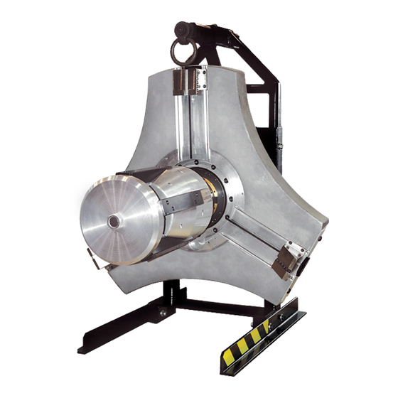
Page 6: General Description
TRI TOOL INC. GENERAL DESCRIPTION The Model 236B BEVELMASTER™ is a portable I.D. mount machine tool for beveling, facing and/or counterboring 12” through 36” pipe. The tool is configured with an in line feed knob and hydraulic drive motor at a right angle to the lathe head. -
Page 7: Specifications
Model 236B BEVELMASTER™ SPECIFICATIONS The Model 236B BEVELMASTER™ is designed for facing, beveling and/or counterboring the ends of pipe or tubing in preparation for welding. These machining operations may be performed either simultaneously or separrately. Pipe weld preparations that meet all existing conventional codes including the more stringent nuclear codes may be machined using the Model 236B. - Page 8 TRI TOOL INC. Avoid unintentional starts. Do not carry or handle tools with your hand on the operating switches or levers. Do not lay the tool down in a manner which will start the drive. Do not allow the tool to flip around or move when adjusting or changing tool bits.
- Page 9 Tubing or pipe with a greater wall thickness may be handled provided the I.D. is greater than 11.43” (290.4 mm) and the O.D. is less than 36.00” (914.4 mm). Contact Tri Tool for heavier wall procedures. Counterboring Operations The tool will counterbore pipe and tubing with an I.D.
-
Page 10: Maintenance
TRI TOOL INC. MAINTENANCE All Components should be cleaned and coated with a light film of oil prior to use. If the Model 236B is operated in the vertical position, Headstock facing up, the chips and/or other debris should be removed after each bevel cut has been completed. - Page 11 Model 236B BEVELMASTER™ Bushing Tightening STORAGE AND TORQUE SPECIFICATIONS Remove the tool bits from the tool holders before storing the machine. If the Model 236B is to be stored or if it will remain out of service for a signifi- cant period of time, 30 days or more, it should be thoroughly cleaned, lubri- cated and sprayed with a rust preventative prior to storage.
- Page 12 TRI TOOL INC. The shoulder screw (Item C) holding the hoist ring to the lifting bracket is to be torqued at 25 ft-lbs (34 N m). There are eight (8) cap screws that hold each gear cover (Item D) onto the main housing.
- Page 13 PINCH POINT - Remove the Lathe Stand Feet Supports BEFORE WARNING: operating.
- Page 14 To select the appropriate Tool Bits refer to the 'Tool Bits' section of this manual to help with your choice. Use of a dull Tool Bit(s) or Tool Bit(s) not manufactured by TRI TOOL Inc. CAUTION: may result in poor performance and may constitute abuse of this machine and therefore voids the TRI TOOL Inc.
- Page 15 Model 236B BEVELMASTER™ The Bevel/Face Tool Block with a Beveling Tool Bit Installed Tool Block Headstock Beveling Tool Bit Pipe OD BEVEL/FACE TOOL BLOCK The Bevel/Face Tool Block is designed with a 37.5° angle so that a Straight Tool Bit may be used for beveling and so that when using the 37.5°...
- Page 16 TRI TOOL INC. COUNTERBORE TOOL BLOCK The Counterobre Tool Block is designed with a 5° back angle to provide Tool Bit clearance. The Counterbore Tool Block with a Counterboring Tool Bit Installed Tool Block Headstock Counterboring Tool Bit Pipe OD...
- Page 17 Model 236B BEVELMASTER™ Final Prep Location Clearance Jaw Block Pipe Mandrel Head Final Prep Location Attach the proper supply line to the Drive Motor. When using an Air Motor, use an adequate in line Filter, Regulator, Lubricator, NOTE: (FRL). Turn the power on. Adjust the cutting speed by opening the Flow Control Valve at the Power Supply connection.
- Page 18 TRI TOOL INC. Discontinue feed and allow the Headstock to rotate one (1) to three (3) revolutions at low rpm to improve the finish of the prep surface. Rotate the Feed Knob counterclockwise to separate the Headstock from the pipe.
- Page 19 Model 236B BEVELMASTER™ Mandrel Stop Location Mandrel Stop (2) 92-1306 : Rev. 090225...
-
Page 20: Cutting Speeds
TRI TOOL INC. CUTTING SPEEDS RPM for RPM for RPM for True Dia Pipe Size 200 in/min 250 in/min 300 in/min (5080 mm/min) (6350 mm/min) (7620 mm/min) 36" 36.00" 914.4 mm 34" 34.00" 863.6 mm 32" 32.00" 812.8 mm 30"... -
Page 21: Standard Jaw Blocks, Ramps And Spacers
Model 236B BEVELMASTER™ STANDARD JAW BLOCKS, RAMPS AND SPACERS (12" THROUGH 36" PIPE) Standard Adapter Jaw Block Adapter Mounting Ramp (5 Req'd) (5 Req'd) (5 Req'd) Range (5 Req'd) 11.433" thru 13.798" 48-0973 (290.4 mm thru 350.5 mm) 12.021" thru 14.471" 48-0973 08-0388 (305.3 mm thru 367.6 mm) -
Page 22: Extension Kit Jaw Blocks, Ramps And Spacers
TRI TOOL INC. EXTENSION KIT JAW BLOCKS, RAMPS AND SPACERS (36" THROUGH 60" PIPE) Standard Adapter Jaw Block Adapter Mounting Ramp (5 Req'd) (5 Req'd) (5 Req'd) Range (5 Req'd) 35.650" thru 38.229" 48-0973 08-0552 08-0388 (905.5 thru 971.0 mm) 38.025"... -
Page 23: Tool Bits
Model 236B BEVELMASTER™ TOOL BITS Tool Bit, Counterbore, 4:1 (P/N 99-1939) 8.50” to 24.00” (216.0mm to 609.6mm) DIA Range Tool Bit, Counterbore, 4:1 (P/N 99-2090) 24.00” to 42.00” (609.6mm to 1066.8mm) DIA Range Tool Bit, Beveling, 37.5° (P/N 99-0009) Tool Bit, Facing (P/N 99-0016) Tool Bits for special applications are quoted upon request. -
Page 24: Trouble Shooting
TRI TOOL INC. TROUBLE SHOOTING Problem: The Tool Bit Chatters The tool bit is loose or overextended. The tool bit is damaged. The tool holder is too loose in the slides. The cutting speed is too fast. The clamping pads are loose on the pipe or tube. - Page 25 Model 236B BEVELMASTER™ Problem: There is a loss of air power The air supply pressure is too low. The air filter is plugged. The air line size is insufficient. The air line is too long. Problem: There is a loss of hydraulic power The hydraulic supply pressure is too low.
-
Page 26: Accessories
TRI TOOL INC. ACCESSORIES The following accessories are recommended for use with the Model 236B BEVELMASTER™ and are available from TRI TOOL INC. Single Point Module Kit I.D. Tracking Module Kit Miter Mandrel Head Kit Jaw Block Extension Kit (36" - 60") Miter Mandrel Extension Kit (36"... -
Page 27: Illustrated Parts Breakdown
Model 236B BEVELMASTER™ ILLUSTRATED PARTS BREAKDOWN MODEL 236B BEVELMASTER™ (P/N 01-1850) 92-1306 : Rev. 090225... - Page 28 TRI TOOL INC. Parts List, Model 236B BEVELMASTER™ (P/N 01-1850) Item Part Description 02-2395 MODEL 236B SUB-ASSEMBLY 06-0432 MANDREL ASSEMBLY 08-0388 BLOCK SET, JAW, .400"/10.2 mm 08-0389 BLOCK ASSEMBLY, JAW, 1.590"/40.4 mm 08-0390 BLOCK ASSEMBLY, JAW, 2.780"/70.6 mm 08-0391 BLOCK ASSEMBLY, JAW 3.970"/100.8 mm 08-0392 BLOCK ASSEMBLY, JAW, 5.160"/131.1 mm...
- Page 29 Model 236B BEVLEMASTER™ MODEL 236B SUB-ASSEMBLY 1 of 3 (P/N 02-2395) Parts List, Model 236B Sub-Assembly (P/N 02-2395) Item Part Description 19-0843 HOUSING, SHAFT 19-0844 HOUSING, MAIN TORQUE 19-0845 HOUSING, FEED 230B 19-1193 HOUSING, MAIN, 236B 92-1306 : Rev. 090225...
- Page 30 TRI TOOL INC. MODEL 236B SUB-ASSEMBLY 2 of 3 (P/N 02-2395) Parts List, Model 236B Sub-Assembly (P/N 02-2395) Continued Item Part Description 20-0628 SHAFT 20-0720 SHAFT, FEED 24-1468 PLATE, COVER 24-2692 PLATE, MAIN, 236B 24-2702 PLATE, COVER 28-0057 SEAL, FELT, 1/8" X 3/16" X BULK 28-0176 SEAL, EXTRUDED 3/16"...
- Page 31 Model 236B BEVLEMASTER™ MODEL 236B SUB-ASSEMBLY 3 of 3 (P/N 02-2395) 58 59 60 Parts List, Model 236B Sub-Assembly (P/N 02-2395) Continued Item Part Description 28-0254 SEAL, 2.750" ID X 3.500" OD X .375" 28-0262 O-RING, 7.734" ID X .139" W 29-0020 BRG, BALL, 3/4 X 1 5/8 X 7/16 29-0337...
- Page 32 TRI TOOL INC. Parts List, Model 236B Sub-Assembly (P/N 02-2395) Continued Item Part Description 29-0340 BRG, TAPER CUP, 10.563" OD X .728" 29-0341 BRG, TAPER CONE, 15.875" ID X 1.125" 29-0342 BRG, TAPER CUP, 18.125" OD X .813" 29-0343 BRG, TAPERED CONE, 2.75" ID X 1.188"...
- Page 33 Model 236B BEVLEMASTER™ Parts List, Model 236B Sub-Assembly (P/N 02-2395) Continued Item Part Description 35-0502 NUT, LOCK 35-0550 NUT, LOCK 39-0795 WORM GEAR SET, 230B 39-0796 GEAR, FEED, 60T 39-0798 GEAR, IDLER, 24T 39-0867 GEAR, PINION, 24T 41-0131 HANDLE, FEED 42-0017 KNOB, SPHERICAL, #1-3/8 DIA 42-0185...
- Page 34 TRI TOOL INC. HYDRAULIC MOTOR ASSEMBLY (P/N 56-0061) REF. Parts List, Hydraulic Motor Assembly (P/N 56-0061) Item Part Description 33-0106 SCREW, CAP, 1/2-13 X 1 1/4” 54-0002 ADAPTER 54-0333 COUPLER, QD, HYD., DRIPLESS, FEMALE 54-0334 COUPLER, QD, HYD., DRIPLESS, MALE...
- Page 35 Model 236B BEVLEMASTER™ MANDREL ASSEMBLY (P/N 06-0432) Parts List, Mandrel Assembly (P/N 06-0432) Item Part Description 13-0443 MANDREL 20-0719 SHAFT, WRENCH 35-0448 NUT, FEED 33-0055 SCREW, CAP, 5/16-18 X 7/8” 31-0160 KEY, MANDREL 44-0502 SPACER 34-0148 WASHER 30-2935 INSERT, THREADED 33-0531 SCREW, SET, 3/8-16 X 3/4”...
- Page 36 TRI TOOL INC. MANDREL HEAD ASSEMBLY (P/N 21-0518) Parts List, Mandrel Head Assembly (P/N 21-0518) Item Part Description 21-0520 HEAD, MANDREL 24-1621 PLATE, BUTT 24-1465 PLATE, RETAINING 33-0287 SCREW, BUTTON HEAD, 1/4-20 X 3/4” 23-0319 DRAW ROD 35-0538 NUT, HEX...
- Page 37 Model 236B BEVLEMASTER™ TOOL HOLDER ASSEMBLY (P/N 49-XXXX) Parts List, Bevel/Face Tool Holder Assembly (P/N 49-0394) Item Part Description 33-0057 SCREW, CAP, 5/16-18 X 1 1/4” 33-0530 SCREW, SET, CUP POINT, 3/8-16 X 5/8” 35-0551 NUT, T-SLOT PLATE 49-0365 HOLDER, TOOL, BEVEL/FACE Parts List, C'Bore Tool Holder Assembly (P/N 49-0395) Item Part...
- Page 38 TRI TOOL INC. LATHE STAND ASSEMBLY (P/N 60-0099) 92-1306 : Rev. 090225...
- Page 39 Model 236B BEVLEMASTER™ Parts List, Lathe Stand Assembly (P/N 60-0099) Item Part Description 30-0304 RING, HOIST, 1/2-13 33-1972 SCREW, HEX HD CAP, 1/2-13 X 3" 34-0020 WASHER, FLAT, SAE, 1/2" NOMINAL 35-0254 NUT, LK, 1/2-13 47-1222 BRACKET, LIFTING 60-0100 LATHE STAND, UPPER, 236B 60-0098 LATHE STAND, LOWER, 236B 33-2132...
Need help?
Do you have a question about the BEVELMASTER 236B and is the answer not in the manual?
Questions and answers