TRI tool BEVELMASTER 204B Manual
Hide thumbs
Also See for BEVELMASTER 204B:
- Operation manual (46 pages) ,
- Operation manual (55 pages) ,
- Operation manual (54 pages)

Related Manuals for TRI tool BEVELMASTER 204B


Summary of Contents for TRI tool BEVELMASTER 204B
-
Page 1: Table Of Contents
TABLE OF CONTENTS CUSTOMER MESSAGE Inside Front Cover SAFETY PRECAUTIONS GENERAL DESCRIPTION SPECIFICATIONS MAINTENANCE OPERATION CUTTING SPEEDS AND FEEDS JAW BLOCKS AND RAMP SETS TOOL BITS TROUBLE SHOOTING ACCESSORIES ILLUSTRATED PARTS BREAKDOWN TOOL BIT RESHARPENING POLICY Inside Back Cover WARRANTY INFORMATION Inside Back Cover... - Page 2 Copyright 2006 Proprietary property of TRI TOOL Inc. No reproduction, use, or duplication of the information shown hereon is permitted without the express written consent of TRI TOOL Inc.
-
Page 3: Safety Precautions
Model 204B BEVELMASTER™ SAFETY PRECAUTIONS IN GENERAL When using rotating head cutting equipment, basic safety precautions should always be followed to reduce the risk of personal injury. Operate this tool only in accordance with specific operating instructions. Do not override the deadman switch on the power unit. Locking down, ob- WARNING: structing, or in any way defeating the deadman switch on the power drive unit may result in serious injury. - Page 4 TRI TOOL INC. TOOL CARE Maintain tools with care. Keep tools in good operating condition. Sharp tool bits perform better and safer than dull tool bits. Well maintained tools function properly when needed. Check for damaged parts. If a tool has malfunctioned, been dropped or hit, it must be checked for damage.
- Page 5 Model 204B BEVELMASTER™ Disconnect power supply during setup and maintenance. Use all ‘Stop’ or Shut off’ features available when changing or adjusting tool bits, maintaining the tool, or when the tool is not in use. Remove adjusting keys and wrenches before applying power to the equipment. Develop a habit of checking the tool before turning it on to make sure that all keys and wrenches have been removed.
-
Page 6: General Description
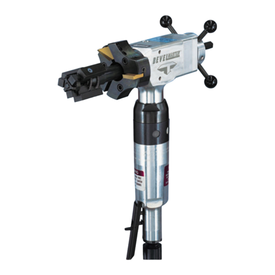
TRI TOOL INC. GENERAL DESCRIPTION The Model 204B BEVELMASTER™ is a Pipe Beveler designed for facing, beveling and/or counterboring the ends of pipe or tubing in preparation for welding. These machining operations may be performed either simultaneously or separately. Pipe weld end preparations that meet all existing conventional codes including the more stringent nuclear codes may be machined. -
Page 7: Specifications
Model 204B BEVELMASTER™ SPECIFICATIONS MODEL 204B BEVELMASTER™ with an AIR MOTOR Weight 18 lbs (8.1 kg) Power Requirements 55 cfm at 90 psi (26 L/s at 621 kPn) Envelope Drawing 16.42" (417.1 mm) 4.00" 8.97" (101.6 mm) (227.8 mm) 7.18" (182.4 mm) Mandrel Cutting Head... - Page 8 Wall Thickness Capacity Wall thickness of all standard pipe schedules [.531” (13.5mm) maximum] in the range listed. Contact Tri Tool for heavier wall procedures. Counterboring Operations The tool will counterbore pipe and tubing with an I.D. range of 1.50” (38.1mm) to 4.33”...
- Page 9 Model 204B BEVELMASTER™ DRIVE SYSTEM Final Drive Gear Driven Pneumatic Motor Free speed 325 rpm Max. H.P. speed 162 rpm POWER SUPPLY Pneumatic motor requires 55 cfm ( 26 L/s ) air supply at 90 psi ( 621 kPa ) for maximum horsepower delivery.
- Page 10 TRI TOOL INC. MODEL 204B BEVELMASTER™ with an ELECTRIC MOTOR Weight 18 lbs (8.1 kg) Power Requirements 115 VAC, 28 to 60 Hz 5.25 amp Envelope Drawing 16.57" (420.88 mm) 4.00" 8.79" (101.60 mm) (223.27 mm) 7.03" (178.56 mm) Mandrel In-line Feed 20.25"...
- Page 11 Model 204B BEVELMASTER™ PIPE CUTTING CAPACITIES Basic Pipe Sizes 1” Pipe Schedule 40 (Small Mandrel required to mount in 1” schedule 80 and above.) 1 1/4” through 2 1/2” Pipe Up to Schedule 80 3” through 4” Pipe Up to Schedule 40 * Some Schedules may require optional equipment.
- Page 12 Inconel and some other high temperature alloys may require special procedures as a function of wall thickness and type of end preparations. Contact Tri Tool’s Engineering Department for details. CLEARANCE AND DIMENSIONS Rotating Head DIA.
- Page 13 Model 204B BEVELMASTER™ CUTTING HEAD SPEEDS Max. Cutting Head Speed Low Range 84 rpm High Range 156 rpm Cutting Head Speed @ Max. H.P. Low Range 56 rpm High Range 105 rpm Functional Speed Range 20 to 100 rpm Speed Control On/Off Trigger control with Variable Speed.
-
Page 14: Maintenance
TRI TOOL INC. MAINTENANCE All components should be cleaned and coated with a light film of oil prior to use. Use a clean, non-detergent oil, preferably SAE 10 (90 SSU) or lighter or oil as specified for the air motor. - Page 15 Grease Port Disassembly of a power unit voids warranty, except when performed by a NOTE: TRI TOOL INC. designated repair technician. A letter of designation is required. AIR MOTOR LUBRICATION No direct maintenance is normally required on the air motor.
- Page 16 The air motor requires a Class 2 lubricant, viscosity of 100 to 200 SSU at F (38° C) minimum aniline point of 200° F (93° C). ° TRI TOOL Inc. – Air Tool Lubricant (P/N 68-0022) • AMOCO – American Industrial Oil No. 32 • Atlantic Richfield – Duro Oil S 150 •...
-
Page 17: Operation
Model 204B BEVELMASTER™ OPERATION Read the operating instructions carefully before attempting to operate the Model 204B BEVELMASTER™ Use eye protection at all times when operating the Model 204B BEVELMASTER™ INSTALLATION Select the recommended jaw blocks for the pipe size to be machined. Gently slide the mandrel assembly into the Model 204B BEVELMASTER™... - Page 18 TRI TOOL INC. Final Prep Draw Nut Jaw Block Location and/or Pipe Ramp Mandrel Assembly In order to avoid cutting the ramps and/or jaw blocks during the machining NOTE: operation, the mandrel must be installed beyond the final preparation location.
- Page 19 Use of dull or improperly designed tool bits or tool bits not manufactured by WARNING: TRI TOOL INC. may result in poor performance and may constitute abuse of the machine and therefore voids the TRI TOOL INC. factory warranty. Cam Adjustment...
- Page 20 TRI TOOL INC. Tool Bit Cutting Edge Set Screws Rotation NOTE: Check that the filter/regulator/lubricator (FRL) is installed and set properly. MACHINING SEQUENCE Depress the air motor trigger. Adjust the cutting speed by rotating the flow valve at the air connection.
- Page 21 Model 204B BEVELMASTER™ To avoid tool bit damage, the feed rate should be very slow until the tool bit(s) is in contact with the pipe continually during at least one full revolution. Continue rotating the feed handle clockwise until the end of the pipe is completely machined.
-
Page 22: Cutting Speeds And Feeds
TRI TOOL INC. CUTTING SPEEDS AND FEEDS RPM for RPM for RPM for Pipe Size True DIA 200 in/min 250 in/min 300 in/min (5080 mm/min) (6350 mm/min) (7620 mm/min) 1" 1.315" 33.4 mm 2" 2.375" 60.3 mm 3" 3.500" 88.9 mm 3 1/2"... - Page 23 Model 204B BEVELMASTER™ If the feed is too heavy the drive will start to overload and the chip will start to have a rough or torn appearance. Stainless steel, which work hardens, must be worked with a heavy enough feed to stay under the work hardened surface .003"...
-
Page 24: Jaw Blocks And Ramp Sets
TRI TOOL INC. JAW BLOCKS AND RAMP SETS STEEL JAW BLOCKS AND RAMPS Ramp Block Mandrel Assembly Used with Mandrel Assembly (P/N 06-0419) Standard Jaw Block Block Mounting Ramp Assembly Height Range (3 Req'd) (3 Req'd) 1.250" to 1.630" 48-0964 (31.8 mm to 41.4 mm) - Page 25 Model 204B BEVELMASTER™ STEEL JAW BLOCK AND RAMP PROFILES - STANDARD MANDREL Mounting ID Ramp and Block Combination 1.250" to 1.630" (31.8 mm to 41.4 mm) 1.560" to 2.000" (39.6 mm to 50.8 mm) 1.930" to 2.390" (49.0 mm to 60.7 mm) 2.320"...
- Page 26 TRI TOOL INC. STEEL JAW BLOCK AND RAMP PROFILES - STANDARD MANDREL Mounting ID Ramp and Block Combination 3.480" to 3.940" (88.4 mm to 100.1 mm) 3.870" to 4.330" (98.3 mm to 110.0 mm) 92-0699 : Rev. 060412...
- Page 27 Model 204B BEVELMASTER™ BUTT PLATE, SPRING AND RAMPS Butt Plate Mandrel Sleeve Ramp Mandrel Assembly Spring Used with Mandrel Assembly (P/N 06-0413) Butt Spring Ramp M ounting Plate Range .610" to .800" 24-1463 40-0130 48-0596 (15.5 mm to 20.3 mm) .800"...
-
Page 28: Tool Bits
TRI TOOL INC. TOOL BITS TOOL BIT, 37.5° BEVELING Pipe Cutting Head Cutting Edge Tool But, Beveling Pipe 37.5° M ax. Beveling Range Wall T ube T ool Bit T hickness M at'l 1 1/4" ID thru 3" pipe .531" (13.5 mm) 99-0333 (31.8 mm ID thru 88.9 mm OD) - Page 29 Model 204B BEVELMASTER™ TOOL BIT, BEVELING AND FACING Facing Tool Bit Pipe Cutting Head Cutting Edge Tool Bit, Beveling Pipe 37.5° Max. Facing Beveling Wall Tool Bit Range Tube Tool Bit Thickness Mat'l 1 1/4" pipe - sch 10 thru 40 up to .531"...
- Page 30 TRI TOOL INC. TOOL BIT, FACING (LAND) Pipe Cutting Head Cutting Edge Tool Bit, Facing (Land) M ax. Pipe or Facing Range Wall T ube T ool Bit T hickness M at'l 1 1/4" ID thru 4" pipe .531" (13.5 mm) 99-0485 (31.8 mm ID thru 114.3 mm OD)
- Page 31 Model 204B BEVELMASTER™ TOOL BIT, ID CHAMFER Cutting Head Pipe Cutting Edge Tool Bit, ID Chamfer Pipe ID Chamfer Range or T ube T ool Bit M aterial 1.60" ID thru 2.66" ID 99-0168 (40.6 mm thru 67.6 mm) 1.60" ID thru 2.66" ID 99-3713 (40.6 mm thru 67.6 mm) 2.14"...
-
Page 32: Trouble Shooting
TRI TOOL INC. TROUBLE SHOOTING Problem: The Tool Bit Chatters The tool bit is loose or overextended. The tool bit is damaged. The tool holder is too loose in the slides. The cutting speed is too fast. The clamping pads are loose on the pipe or tube. - Page 33 Model 204B BEVELMASTER™ Problem: There is a loss of hydraulic power The hydraulic supply pressure is too low. The hydraulic filter is plugged. The hydraulic line size is insufficient. The hydraulic line is too long. Problem: The hydraulic motor will not start The hydraulic power supply is shut off.
-
Page 34: Accessories
Pointer Kit, Elbow Mandrel 204B (P/N 05-0316) Indicator Kit, Dial (P/N 05-0317) 10. Adjustable Pin Kit, Elbow Mandrel (P/N 05-0355) A portable Air Caddy (FRL) is required to protect the warranty on all TRI TOOL INC air driven tools. 92-0699 : Rev. 060412... -
Page 35: Illustrated Parts Breakdown
Model 204B BEVELMASTER™ ILLUSTRATED PARTS BREAKDOWN MODEL 204B BEVELMASTER™ SUB-ASSEMBLY (P/N 02-2222) 92-0699 : Rev. 060412... - Page 36 TRI TOOL INC. MODEL 204B BEVELMASTER™ SUB-ASSEMBLY (P/N 02-2222) Con't 92-0699 : Rev. 060412...
- Page 37 Model 204B BEVELMASTER™ Parts List, Model 204B BEVELMASTER™ Sub-Assembly (P/N 02-2222) Item Part Description 19-0764 HOUSING, MAIN 19-0729 HOUSING, FEED 20-1025 SHAFT, MAIN 27-0513 ADAPTER, FEED 28-0248 O-RING 29-0005 BEARING, BALL 29-0326 BEARING, BALL 29-0327 BEARING, BALL 29-0328 BEARING, TAPER, CONE 29-0329 BEARING, TAPER, CUP 29-0345...
- Page 38 TRI TOOL INC. Parts List, Model 204B BEVELMASTER™ Sub-Assembly (P/N 02-2222) Con't Item Part Description NOT SHOWN 05-1327 WRENCH KIT, 204B 36-0004 WRENCH, L, 7/64" HEX 36-0006 WRENCH, L, 9/64" HEX 36-0007 WRENCH, L, 5/32" HEX 36-0010 WRENCH, L, 1/4" HEX 36-0018 WRENCH, T, 1/8"...
- Page 39 Model 204B BEVELMASTER™ MOTOR ASSEMBLY, AIR (P/N 57-0224) Parts List, Motor Assembly, Air (P/N 57-0224) Item Part Description 53-0046 VALVE, FLOW CONTROL 54-0126 COUPLING, MALE QD 54-0201 CAP, YELLOW 57-0223 MOTOR, INLINE AIR 92-0669 : Rev. 060412...
- Page 40 TRI TOOL INC. ELECTRIC MOTOR ASSEMBLY, 220V, 110V Parts List, Electric Motor Assembly, 220V Item Part Description 58-0133 MOTOR ASSEMBLY, 220V 58-0039 MOTOR, MOD, ELECTRIC, 220V 27-0357 ADAPTER, MOTOR 39-0568 GEAR, DRIVE 29-0182 BEARING, BALL, 1/2" X 1 1/8" X 3/8"...
- Page 41 Model 204B BEVELMASTER™ Parts List, Electric Motor Assembly, 110V Item Part Description 58-0147 MOTOR ASSEMBLY, 110V 58-0038 MOTOR, MOD, ELECTRIC, 110V 27-0357 ADAPTER, MOTOR 39-0568 GEAR, DRIVE 29-0182 BEARING, BALL, 1/2" X 1 1/8" X 3/8" 91-0545 GEAR ASSEMBLY 33-0039 SCREW, CAP, 1/4-20 X 5/8"...
- Page 42 TRI TOOL INC. CUTTING HEAD KIT, 4" DIA (P/N 03-0049) Parts List, Cutting Head Kit, 4" DIA (P/N 03-0049) Item Part Description 21-0475 HEAD, 4.0" DIA 28-0249 SEAL, OIL 33-0057 SCREW, CAP, 5/16-18 X 1 1/4" 33-0514 SCREW, SET, 5/16-18 X 3/8", CUP PT 33-0517 SCREW, SET, 5/16-18 X 5/8", CUP PT...
- Page 43 Model 204B BEVELMASTER™ MANDREL ASSEMBLY (P/N 06-0413) Parts List, Mandrel Assembly (P/N 06-0413) Item Part Description 13-0429 MANDREL 23-0298 ROD, DRAW 24-1463 PLATE, BUTT #1 24-1464 PLATE, BUTT #2 33-0477 SCREW, SET, #8-32 X 3/16", CUP PT 33-0478 SCREW, SET, #8-32 X 1/4", CUP PT 35-0523 NUT, DRAW ROD, 3/8-16 40-0130...
- Page 44 TRI TOOL INC. MANDREL ASSEMBLY (P/N 06-0414) Parts List, Mandrel Assembly (P/N 06-0414) Item Part Description 13-0426 MANDREL 23-0297 ROD, DRAW 24-1462 PLATE, BUTT 33-0489 SCREW, SET, #10-24 X 5/16", CUP PT 35-0523 NUT, DRAW ROD, 3/8-16 40-0108 SPRING, EXTENSION...
- Page 45 Model 204B BEVELMASTER™ MANDREL ASSEMBLY (P/N 06-0419) Parts List, Mandrel Assembly (P/N 06-0419) Item Part Description 08-XXXX BLOCK, JAW (Ref. the ‘Jaw Blocks’ section.) 13-0424 MANDREL 23-0295 ROD, DRAW 24-1384 PLATE, BUTT 33-0490 SCREW, SET, #10-24 X 3/8", CUP PT 35-0523 NUT, DRAW ROD, 3/8-16 40-0001...
Need help?
Do you have a question about the BEVELMASTER 204B and is the answer not in the manual?
Questions and answers