Table of Contents

Related Manuals for Avalue Technology HID-2340


Summary of Contents for Avalue Technology HID-2340
- Page 1 Avalue Intelligent Display & System HID-2340 23.8" Alder Lake Medical Panel PC User Manual Ed- 15 September 2023 Copyright © 2023 Avalue Technology Inc., All Rights Reserved. DMR No: T86027-00 Part No: E2017H300A0R Rev: 1...
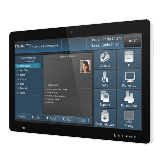
- Page 2 Please contact a service technician or your retailer. Purposes and Applications HID-2340 is intended to be used in healthcare institutions for general purpose as an assisting device for data access – patient information, medical records, media services, and so on. The product is designed for general or special use in the hospital environment.
- Page 3 3. Repair of the device may also only be carried out by Warning! Because of the danger of electric shock, never remove the cover of a device while it is in operation or connected to a power outlet. HID-2340 Quick Reference Guide...
- Page 4 6. Put this equipment on a reliable surface during installation. Dropping it or letting it fall may cause damage. For plug-in equipment, the power outlet socket must be HID-2340 Quick Reference Guide...
- Page 5 Précaution! Ne remplacez pas la batterie vous-même. Veuillez contacter le FABRICANT. L'ordinateur est équipé d'un circuit d'horloge en temps réel alimenté par batterie. Il existe un risque d'explosion si la batterie n'est pas remplacée correctement. Remplacez uniquement par un type identique HID-2340 Quick Reference Guide...
- Page 6 IEC 60601-1-1. Everybody who connects additional equipment to the signal input part or signal output part configures a medical system, and is therefore, responsible that the system complies with the HID-2340 Quick Reference Guide...
- Page 7 Warning! To avoid risk of electric shock, this equipment must only be connected to a supply main with protective earth. Caution! This adapter EDAC EM11011M(18) is a forming part of the medical device. Attention! Ne modifiez pas cet équipement sans l'autorisation du fabricant. HID-2340 Quick Reference Guide...
- Page 8 MANUFACTURER to replace battery packs. Précaution! Do not use the power adapter that isn’t made for the equipment, supplying the equipment with inappropriate voltage may cause harm to the battery (if any) or even worse burn the equipment. HID-2340 Quick Reference Guide...
- Page 9 Attention! Risque d'explosion si la batterie est remplacée par un type incorrect. Jetez les piles usagées selon les instructions 17. The product is not used in Category AP or Category APG in an anesthetic gas environment. HID-2340 Quick Reference Guide...
- Page 10 Explanation of Graphical Symbols Warning: dangerous voltage Caution Note ISO 7000-1641: Follow operating instructions or Consult instructions for use. Direct current. Equipotential Stand-by US Conformance Follow the national requirements for disposal of equipment. Stacking layer limit This side up HID-2340 Quick Reference Guide...
- Page 11 HID-2340 User Manual Fragile Packaging Beware of water damage, moisture-proof Carton recyclable Handle with care Storage &Transportation Temperature: -20°C ~ 60°C Storage &Transportation Humidity: 10% ~ 95% HID-2340 Quick Reference Guide...
- Page 12 • Reorient or relocate the receiving antenna. • Increase the separation between the equipment and receiver. HID-2340 Quick Reference Guide...
- Page 13 Selection of other channels is not possible. The antenna(s) used for this transmitter must not be co-located or operating in conjunction with any other antenna or transmitter. Shielded interface cables must be used in order to comply with emission limits. HID-2340 Quick Reference Guide...
- Page 14 EMI sensitive devices in its surrounding which may malfunction therefore. Environmental protection ◼ Follow national requirements to dispose of unit. Manufacturer Avalue Technology Inc. 7F, No.79, Lide St., Zhonghe District, New Taipei City, 235, Taiwan TEL: +886-2-8226-2345 FAX: +886-2-8226-2777 Web: www.avalue.com Information: sales@avalue.com.tw HID-2340 Quick Reference Guide...
-
Page 15: Table Of Contents
HID-2340 User Manual CONTENT 1. HID-2340 Multi Touch Medical Panel PC Features ........ 17 1.1 Packing List ..................17 1.2 Specifications ..................18 1.3 Front view ..................21 1.4 Rear & Bottom view ................22 1.6 System Dimensions ................23 2. - Page 16 5.7.3 Serial port 1 connector (JCOM1) ..........59 5.7.4 B2B connector (B2B1) ............60 5.8 HID-2340 DB-B Connector list ............61 5.9 HID-2340 DB-B Jumpers & Connectors settings ......62 5.9.1 Serial port 1 in RS-232/422/485 mode (JCOMSEL1) ..... 62 5.9.2 Audio connector (JMIC1) ............62 5.9.2.1 Signal Description –...
-
Page 17: Hid-2340 Multi Touch Medical Panel Pc Features
HID-2340 User Manual 1. HID-2340 Multi Touch Medical Panel PC Features ▬▬▬▬▬▬▬▬▬▬▬▬▬▬▬▬▬▬▬▬▬▬▬▬▬▬▬▬▬▬▬▬▬▬ In this chapter, you will get to know all features of our HID-2340 Multi Touch Medical Panel PC. 1.1 Packing List 1 x HID-2340 Medical Panel PC ⚫... -
Page 18: Specifications
1 x COM Serial Port (RS-232/422/485, selectable by BIOS & JUPMER) 3 x USB Gen2X1 1 x USB 2.0 USB Port 1 x USB Type C (Output for USB 3.1 & Display, 5V/3A 15W, No power receiving function) HID-2340 Quick Reference Guide... - Page 19 3 Sweep:1 Oct/ per one minute. (logarithmic) 4 Test axis : X,Y and Z axis 5 Test time :30 min. each axis 6 System condition : Non-Operating mode 7 Test curve Package Vibration Test: Reference IEC60068-2-64 Testing procedures HID-2340 Quick Reference Guide...
- Page 20 With CF/SSD: 10Grms, IEC 60068-2-27, Half Sine, 11ms Operating Temperature 0°C ~ 40°C (32°F ~ 104°F) Operating Humidity 40°C @ 95% Relative Humidity, Non-condensing Storage Temperature -10°C ~ 60°C (14°F ~ 140°F) Note: Specifications are subject to change without notice. HID-2340 Quick Reference Guide...
-
Page 21: Front View
HID-2340 User Manual 1.3 Front view Camera Power Icon Backlight Icon Touchscreen Brightness Volume Reading Icon Up/down Icon Up/down Icon Light Icon HID-2340 Quick Reference Guide... -
Page 22: Rear & Bottom View
COM: for Mouse/Ethernet..etc serial port device HDD LED: indicate HDD activities status PWR LED: indicate power status Note! Equipotential terminal needs to be linked to the hospital ground/earth system before booting the system to protect both operator and system HID-2340 Quick Reference Guide... -
Page 23: System Dimensions
HID-2340 User Manual 1.6 System Dimensions (Unit: mm) HID-2340 Quick Reference Guide... -
Page 24: Setting Up Hid-2340 Multi Touch Panel Pcs
HID-2340 User Manual 2. Setting Up HID-2340 Multi Touch Panel PCs ▬▬▬▬▬▬▬▬▬▬▬▬▬▬▬▬▬▬▬▬▬▬▬▬▬▬▬▬▬▬▬▬▬▬ This chapter gives instructions on how to set up HID-2340 Multi Touch Panel PC and how to connect different cables. 2.1 VESA Mounting 2.2 Cleaning and Disinfecting HID-2340 Quick Reference Guide... -
Page 25: Vesa Mounting
Installation instructions follow: First attach the wall-mounting to the heat-sink of the HID-2340, securing it in place with four of the M4 x 6mm screws provided. Mount the on the wall, stand or other flat surface. - Page 26 Suggested Screw type for mounting Note: 4 pieces of M4 x 8mm~10mm screws Warning! Use suitable mounting apparatus to avoid risk of injury. Attention! Utilisez un appareil de montage approprié pour éviter tout risque de blessure. HID-2340 Quick Reference Guide...
-
Page 27: Cabling
Follow below step Connecting the Ground pin 1. With system ready, find the equipotential terminal on the rear side of the HID-2340. An equipotential terminal is provided to optionally connect to a hospital ground/earth system. 2. Prepare grounding cable and the other terminal links to the hospital ground/ earth system. - Page 28 HID-2340 User Manual Please follow below steps to connect power cable to system. The HID-2340 could only be powered by a DC power adapter (EDAC Model no. EM11011M(18)). Be sure to always handle the power cords by holding the plug ends only.
-
Page 29: Cleaning And Disinfecting
HID-2340 User Manual 2.3 Cleaning and Disinfecting During normal use of HID-2340, the device may become dirty and should be regularly cleaned. Cleaning Instructions 1. Turn off the computer before starting clean up. This way, you can see any dirt on the screen; the brightness of the monitor may make you miss some areas. - Page 30 Windex Caution! ◼ Do not immerse or rinse the HID-2340 or its peripherals. If you accidentally spill liquid on the device, disconnect the unit from the power source. Contact your Biomed Department regarding the continued safety of the unit before placing it back in operation.
-
Page 31: Using Hid-2340 Multi Touch Panel Pcs
HID-2340 User Manual 3. Using HID-2340 Multi Touch Panel PCs ▬▬▬▬▬▬▬▬▬▬▬▬▬▬▬▬▬▬▬▬▬▬▬▬▬▬▬▬▬▬▬▬▬▬ This chapter describes in detail all features of HID-2340 Multi Touch Panel PC. 3.1 Turn ON/OFF the System 3.2 Using LCD Display and Touch Screen HID-2340 Quick Reference Guide... -
Page 32: Turn On/Off The System
1. Press on the Power ON/OFF icon firmly for 4 seconds. 2. The Power ON/OFF LED will turns orange to indicate power is off. 3. Your system is turned OFF. Note: We recommend using operating system shut down procedure to turn the system OFF. HID-2340 Quick Reference Guide... -
Page 33: Using Lcd Display And Touch Screen
Terminal is forced shutdown operating Power icon shows solid orange 3.2.2 Volume Control User Behavior Volume Status Short press volume up icon Volume level being turned up Short press volume down icon Volume level being turned down HID-2340 Quick Reference Guide... -
Page 34: Adjust Lcd Display Brightness
User Behavior Reading Lights Status Short press reading light icon Reading lights are on at the bottom of the terminal Short pressed reading light icon again Reading lights are off at the bottom of the terminal HID-2340 Quick Reference Guide... -
Page 35: Hid-2340 Installation Figure
HID-2340 User Manual 4. HID-2340 Installation Figure ▬▬▬▬▬▬▬▬▬▬▬▬▬▬▬▬▬▬▬▬▬▬▬▬▬▬▬▬▬▬▬▬▬▬ In this chapter, you will learn how to install storage into HID-2340. Please perform these steps with care. ▲ WARNING: Turn OFF the system and disconnect the power cable before performing the following tasks. -
Page 36: Desktop Stand Installation
HID-2340 User Manual 4.1 Desktop Stand installation Step1. Position VESA Mount on both sides, matching the holes on the system. Step2. Insert and fasten 4 screws on each side of the monitor to secure Mounting brackets. HID-2340 Quick Reference Guide... -
Page 37: Barcode Scanner Kit Installation
HID-2340 User Manual 4.2 Barcode Scanner Kit Installation Step1. Remove the I/O cover. Step2. Install the barcode scanner kit bracket with two screws as indicated. Step3. Re-install the I/O cover. HID-2340 Quick Reference Guide... -
Page 38: Storage Installation
HID-2340 User Manual 4.3 Storage installation Step1. Remove 4 screws to release the chassis cover and remove it. Step2. Insert the HDD back and fasten 4 screws. HID-2340 Quick Reference Guide... -
Page 39: Hardware Configuration
HID-2340 User Manual 5. Hardware Configuration 5.1 HID-2340 Overviews HID-2340 Quick Reference Guide... -
Page 40: Hid-2340 Db-A Overviews
HID-2340 User Manual 5.2 HID-2340 DB-A Overviews 5.3 HID-2340 DB-B Overviews HID-2340 Quick Reference Guide... -
Page 41: Hid-2340 Jumper And Connector List
HID-2340 User Manual 5.4 HID-2340 Jumper and Connector list Jumpers Label Function Note 3 x 1 header, pitch 2.00 mm JRTC1 Clear CMOS LCD backlight brightness adjustment 3 x 1 header, pitch 2.54 mm JSBKL1 3 x 1 header, pitch 2.54 mm... - Page 42 JBAT_AUX1 Battery mode connector 4 x 2 header, pitch 2.00 mm JFAUD1 Front Audio connector 6 x 2 header, pitch 2.00 mm USIM1 SIM card slot JPC1 PC connector 6 x 1 wafer, pitch 1.00 mm HID-2340 Quick Reference Guide...
-
Page 43: Hid-2340 Mb Jumpers & Connectors Settings
HID-2340 User Manual 5.5 HID-2340 MB Jumpers & Connectors settings 5.5.1 Clear CMOS (JRTC1) Protect* Clear CMOS *Default 5.5.2 LCD backlight brightness adjustment (JSBKL1) PWM Mode* DC Mode * Default HID-2340 Quick Reference Guide... -
Page 44: At/Atx Auto Power On Select (Jat1)
HID-2340 User Manual 5.5.3 AT/ATX auto power on select (JAT1) ATX* * Default 5.5.4 M.2 KEY power select (JP1) +3.3V* +3.8V * Default HID-2340 Quick Reference Guide... -
Page 45: Serial Port 1/2 Pin9 Signal Select (Jri1/2)
HID-2340 User Manual 5.5.5 Serial port 1/2 pin9 signal select (JRI1/2) Ring* +12V JRI1 JRI2 * Default 5.5.6 Serial port 1 – RS232/422/485 mode select (JCOM_SEL1) RS-232* RS422/485 * Default HID-2340 Quick Reference Guide... -
Page 46: Front Audio Connector (Jfaud1)
MICIN_L LINEOUT1_JD LINE1-JD MIC1_JD 5.5.7.1 Signal Description –Front Audio connector (JFAUD1) Signal Signal Description LINE1-JD AUDIO IN (LINE_RIN/LIN) sense pin MIC1-JD MIC IN (MIC_RIN/LIN) sense pin 5.5.8 On-board header for USB2.0 (JUSB1) Signal USB2_R_DP5 USB2_R_DN5 +5VSB HID-2340 Quick Reference Guide... -
Page 47: On-Board Header For Usb2.0 (Jusb2)
HID-2340 User Manual 5.5.9 On-board header for USB2.0 (JUSB2) Signal +5VSB HUB1_USB1_R_N HUB1_USB1_R_P 5.5.10 On-board header for USB2.0 (JUSB3) Signal +5VSB HUB1_USB3_R_N HUB1_USB3_R_P HID-2340 Quick Reference Guide... -
Page 48: Speaker_R (Jspkr1)
HID-2340 User Manual 5.5.11 Speaker_R (JSPKR1) Signal SPK_R- SPK_R+ 5.5.12 Speaker_L (JSPKL1) Signal SPK_L- SPK_L+ HID-2340 Quick Reference Guide... -
Page 49: Power Connector (Pwr1)
HID-2340 User Manual 5.5.13 Power connector (PWR1) Signal PIN PIN Signal +VIN_12-24V +VIN_12-24V 5.5.14 Battery connector (BT1) Signal +RTCBATT HID-2340 Quick Reference Guide... -
Page 50: Spi Connector (Jspi1)
HID-2340 User Manual 5.5.15 SPI connector (JSPI1) Signal PIN PIN Signal +3.3VSB +3.3VSB SPI0_CS0# SPI0_BIOS_CLK SPI0_BIOS_MISO SPI0_BIOS_MOSI SPI0_HOLD# BIOS_WP# 5.5.16 EC Debug connector (JEC1) Signal EC_SMCLK_DEBUG EC_SMDAT_DEBUG HID-2340 Quick Reference Guide... -
Page 51: Lcd Inverter Connector (Jbkl1)
HID-2340 User Manual 5.5.17 LCD Inverter connector (JBKL1) Signal LVDS_BKLADJ LVDS_BKLT_EN +12V 5.5.18 Reading Light connector (JLED_LIGHT) Signal +5VSB READ_LIGHT_EN HID-2340 Quick Reference Guide... -
Page 52: Sata Power Connector (Satapw1)
5.5.19 SATA Power connector (SATAPW1) Signal 5.5.20 Front Panel connector (JFPT1) Signal PIN PIN Signal +3.3V BKL_ON_OFF BLK_BRI_UP# READ_LIGHT BLK_BRI_DN# BATTERY_1_O# VOLUME_UP BATTERY_1_B# VOLUME_DN BATTERY_2_O# TOUCH_ON_OFF BATTERY_2_B# EXT_PWRBTN# TOUCH_OFF_LED# PWR_LED- PCH_I2C4_SCL/EC_SMCLK1 17 PS_ON# PCH_I2C4_SDA/EC_SMDAT1 19 +5VSB HID-2340 Quick Reference Guide... -
Page 53: Serial Port 1 Connector (Jcom1)
HID-2340 User Manual 5.5.21 Serial port 1 connector (JCOM1) Signal PIN PIN Signal COM_DCD#_2 COM_RXD_2 COM_TXD_2 COM_DTR#_2 COM_DSR#_2 COM_RTS#_2 COM_CTS#_2 COM_RI#_2 5.5.22 Touch connector (JTP1) Signal SENSE HID-2340 Quick Reference Guide... -
Page 54: Battery Mode Connector (Jbat_Aux1)
HID-2340 User Manual 5.5.23 Battery mode connector (JBAT_AUX1) Signal PIN PIN Signal EC_SMCLK5 DB_AC_SENCE EC_SMDAT5 BAT1_PRSNT +3.3VSB BAT2_PRSNT CHARGER_DISABLE 5.5.24 Power Button connector (PWR_BTN1) Signal EXT_PWRBTN# HID-2340 Quick Reference Guide... -
Page 55: Lvds/Edp Connector (Lvds1)
HID-2340 User Manual 5.5.25 LVDS/eDP connector (LVDS1) Signal PIN PIN Signal +12V +12V LVDS_CLK2N LVDS_CLK1N/EPAUXN LVDS_CLK2P LVDS_CLK1P/EPAUXP LVDS_DATAN7 LVDS_DATAN6 LVDS_DATAP7 LVDS_DATAP6 LVDS_DATAN5 LVDS_DATAN4 LVDS_DATAP5 LVDS_DATAP4 LVDS_DATAN3 LVDS_DATAN2/eDPN1 LVDS_DATAP3 LVDS_DATAP2/eDPP0 LVDS_DATAN1/eDPN1 11 LVDS_DATAN0 LVDS_DATAP1/eDPP1 LVDS_DATAP0/eDP_HPD +3.3V +3.3V HID-2340 Quick Reference Guide... -
Page 56: B2B Connector (Jb2B1)
PCIE_RXN8 Signal PIN PIN Signal PCIE_RXP8 HDMI1_CLKN HDMI1_CLKP CLK_B2BPCIE_N2 +12V CLK_B2BPCIE_P2 +12V MIC_RIN LPC_SERIRQ 46 +5VSB MIC_LIN MIC1_JD LPC_LFRAME# 47 +5VSB CLK3_LPC_B2B 48 +5VSB LINEOUT1_JD LINE1_JD LPC_AD0 49 +5VSB LINEOUT_R LINE1_RIN LPC_AD1 50 +5VSB LINEOUT_L LNE1_LIN HID-2340 Quick Reference Guide... -
Page 57: Pc Connector (Jpc1)
HID-2340 User Manual 5.5.27 PC connector (JPC1) Signal VCCCORE_nPMALERT VCCCORE_PMSDA VCCCORE_PMSCL +3.3VSB HID-2340 Quick Reference Guide... -
Page 58: Hid-2340 Db-A Connector List
HID-2340 User Manual 5.6 HID-2340 DB-A Connector list Jumper Label Function Note JUSB1 USB connector 1 3 x 1 header, pitch 2.00mm 3 x 1 header, pitch 2.00mm JUSB2 USB connector 2 3 x 2 header, pitch 2.00mm JCOMSEL1 COM1 in RS-232/422/485 mode... -
Page 59: Com1 In Rs-232/422/485 Mode (Jcom1_Sel1)
HID-2340 User Manual 5.7.2 COM1 in RS-232/422/485 mode (JCOM1_SEL1) RS232* RS485 RS422 *Default 5.7.3 Serial port 1 connector (JCOM1) Signal PIN PIN Signal NTXD1 NRXD1 NDCD1# NDTR1# HID-2340 Quick Reference Guide... -
Page 60: B2B Connector (B2B1)
5.7.4 B2B connector (B2B1) Signal PIN PIN Signal PCIE_RXP_A PCIE_RXN_A PCIE_TXP_A PCIE_TXN_A 62 LAN_RESET#_A LAN_WAKE#_A PLT_RST#_A PS_ON_A USB_DN_A LPC_AD3_A USB_DP_A LPC_AD2_A Signal PIN PIN Signal LPC_AD1_A +5VSB LPC_AD0_A +5VSB LPC_CLK_A +5VSB LPC_FRAME#_A +5VSB LPC_SERIRQ_A +5VSB 72 PCIE_CLKP_A 71 PCIE_CLKN_A HID-2340 Quick Reference Guide... -
Page 61: Hid-2340 Db-B Connector List
HID-2340 User Manual 5.8 HID-2340 DB-B Connector list Jumper Label Function Note Serial port 1 in RS-232/422/485 3 x 2 header, pitch 2.00mm JCOMSEL1 mode Connectors Label Function Note JCOM1 Serial port 1 connector 5 x 2 header, pitch 2.00mm... -
Page 62: Hid-2340 Db-B Jumpers & Connectors Settings
HID-2340 User Manual 5.9 HID-2340 DB-B Jumpers & Connectors settings 5.9.1 Serial port 1 in RS-232/422/485 mode (JCOMSEL1) RS232* RS485 RS422 *Default 5.9.2 Audio connector (JMIC1) Signal PIN PIN Signal LINE_L_OUT LINE_R_OUT LINE_L_IN LINE_R_IN MIC_L MIC_R LINEIN_JD LINEOUT_JD MIC_JD 5.9.2.1 Signal Description – Audio connector (JMIC1) -
Page 63: Serial Port 1 Connector (Jcom1)
HID-2340 User Manual 5.9.3 Serial port 1 connector (JCOM1) Signal PIN PIN Signal NDCD1# NRXD1 NTXD1 NDTR1# NDSR1# NRTS1# NCTS1# NRI1# 5.9.4 RS-422/RS-485 Termination Resistance connector (JCOMS1) Signal PIN PIN Signal NTXD1 NRXD1 NDCD1 NDTR1# HID-2340 Quick Reference Guide... -
Page 64: Usb Connector 2 (Jusb2)
HID-2340 User Manual 5.9.5 USB connector 2 (JUSB2) Signal USB_DP_R_3 USB_DN_R_3 USBVCC2 HID-2340 Quick Reference Guide... -
Page 65: General Safety Guide
You want to remove/install any parts Thermal The HID-2340 is a fanless design system, heat is dispatch through rear metal heatsink which is located at VESA mount area.. When using your HID-2340 systems, it is normal for the metal heatsink to get warm. The rear metal heatsink of the HID-2340 functions as a cooling surface that transfers heat from inside the computer to the cooler air outside. - Page 66 Handle your HID-2340 with care. It is made of metal, glass, and plastic and has sensitive electronic components inside. Don't use a damaged HID-2340, such as one with a cracked screen, as it may cause injury. Setup HID-2340 on a stable work surface.
Need help?
Do you have a question about the HID-2340 and is the answer not in the manual?
Questions and answers