
Subscribe to Our Youtube Channel
Related Manuals for Avalue Technology CCD-07W01


Summary of Contents for Avalue Technology CCD-07W01
- Page 1 CCD-07W01 / CCD-10W01 series Panel PC USER Manual Ed –17 October 2017 Copyright Notice Copyright 2016 ALL RIGHTS RESERVED.
- Page 2 Copyright © 2016 All rights reserved. All information in this manual is subject to change without notice. No part of this manual may be reproduced or transmitted, in any form or by any means, without the written permission.
- Page 3 Declaration of Conformity CE Conformity Statement Radio products with the CE alert marking comply with the R&TTE Directive (1999/5/EC) issued by the Commission of the European Community. Compliance with this directive implies conformity to the following European Norms (in brackets are the equivalent international standards) ...
- Page 4 Increase the separation between the equipment and receiver Connect the equipment into an outlet on a circuit different from that to which the receiver is connected Consult the dealer or an experienced computer technician for help Technical Support and Assistance Contact your distributor or sales representative for technical support if you need additional assistance.
- Page 5 Battery Safety RTC Battery Caution RISK OF EXPLOSION IF BATTERY IS REPLACED BY AN INCORRECT TYPE. DISPOSE OF USED BATTERIES ACCORDING TO THE INSTRUCTIONS. Do not place the battery incorrectly as this may cause danger of explosion. Dispose of used batteries according to the manufacturer's instructions. ...
-
Page 6: Table Of Contents
Contents CHAPTER 1 ..................- 2 - Understanding Your CCD ..............- 2 - 1.1 Product Features ..................... - 3 - 1.2 Technical Specification .................... - 3 - 1.3 Checking the Delivery Package................- 4 - 1.3.1 Procedure ....................... - 4 - 1.3.2 Packing Contents ................... - Page 7 BIOS Setup (SCU) ................- 20 - 4.1 Overview ....................... - 21 - 4.1.1 Basic Knowledge Required ................- 21 - 4.2 Entering the BIOS Selection Menu ................. - 21 - 4.2.1 Procedure ......................- 21 - 4.3 BIOS Setup (SCU) ....................- 21 - 4.3.1 Structure of the BIOS Setup Menu ..............- 21 - 4.3.2 Navigation and Options Selection ..............- 22 - 4.3.3 Main Menu ....................- 23 -...
-
Page 8: Understanding Your Ccd
CHAPTER 1 Understanding Your CCD Thank you for choosing the CCD series product. We will start here to introduce the basics of CCD. Information described in this chapter includes: features, specification, packing list, I/O ports and appearance giving you an overall picture about your embedded panel PC. - 2 -... -
Page 9: Product Features
1.1 Product Features ▪ Cross-platform capability to satisfy versatile application needs ▪ Streamline, modern design with IPS panel and projected capacitive multi-touch screen, giving excellent user experiences ▪ Ease integration and configuration effort with rich I/O and wireless communication technology ▪... -
Page 10: Checking The Delivery Package
Relative 0 ~ 90%@40°C (non-condensing) Humidity Vibration IEC 60068-2-64, random, 5Grms 5-500Hz, 1Oct./min, 1hr/axis Shock IEC 60068-2-27, half sine, 50G, 11ms Certification CE/FCC Class B Safety 1.3 Checking the Delivery Package 1.3.1 Procedure When accepting a delivery, please check the packaging for visible transport damage. If any transport damage is present at the time of delivery, lodge a complaint at the shipping company in charge. -
Page 11: Optional Accessories
1.4 Optional Accessories This chapter contains the scope of accessories valid at the time these operating instructions were written. ▪ 60W/12V adapter with power cord ▪ 65W/19V adapter with power cord 1.5 Exploring CCD 1.5.1 Dimension ▲ Figure: 7” Panel PC Dimension ▲... -
Page 12: Front View
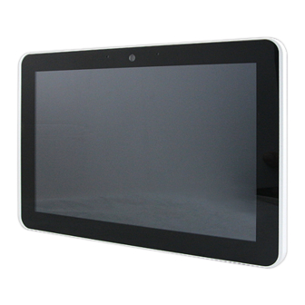
1.5.2 Front View ▲ Figure: 7” Panel PC Front View Description Camera Microphone ▲ Figure: 10.1” Panel PC Front View Description Camera Microphone - 6 -... -
Page 13: Rear View
1.5.3 Rear View ▲ Figure: 7” Rear View Description Speaker ▲ Figure: 10.1” Rear View Description Speaker - 7 -... -
Page 14: Ordering Information
1.6 Ordering Information There are two SKUs – 7” and 10.1” in CCD series, as listed below: Model Description CCD-07W01 CCD-07W01-7V38C-1R 7” Panel PC with Intel®Atom™ Z3735F, 2GB DRAM, 32GB Win10 eMMC, Win10 IoT 2016 ® CCD-07W01 CCD-07W01-7V37C-1R 7” Panel PC with Intel Atom™... -
Page 15: Chapter 2
CHAPTER 2 Hardware Functionality - 9 -... -
Page 16: Power Connector
2.1 Power Connector CCD comes with a round-headed DC-in jack that carries 12 – 24 V external power supply. To prevent damage to the CCD, always use the verified power adapter provided by us. ▲ Figure: DC-in Jack ▲ Figure: Connecting Adaptor via DC-in Jack CAUTION! The power adapter may become warm to hot when in use. -
Page 17: Usb 2.0 Port
▲ Figure: HDMI Connector ▲ Figure: Connecting display via HDMI 2.3 USB 2.0 Port The USB (Universal Serial Bus) 2.0 ports are compatible with USB 1.1 devices such as keyboards, mouse, cameras, and hard disk drives. USB allows many devices to run simultaneously on a single computer with some peripherals acting as additional plug-in hubs. -
Page 18: Ethernet: Lan Port
▲ Figure: Connecting USB Device via USB 2.0 Port 2.5 Ethernet: LAN Port The 8-pin RJ-45 LAN port equipped 10/100 controller which is fully IEEE 802.3 10BASE-T and 802.3u 100BASE-T compliant supports a standard Ethernet cable for connecting to a local network. ▲... -
Page 19: Audio Port
▲ Figure: Connecting network via LAN Port 2.6 Audio Port The supported interface with 3.5 mm audio jack in CCD is: ▪ Line-out ▲ Figure: Audio Jack - 13 -... - Page 20 ▲ Figure: Connecting Audio via Line Out - 14 -...
-
Page 21: Chapter 3
CHAPTER 3 Wireless Connections - 15 -... -
Page 22: Wi-Fi Connection
3.1 Wi-Fi Connection Connecting to a new Wi-fi network with Windows 10 is very easy This may be helpful when setting up a new device or if you're bringing your device to a new place. Follow these steps: NOTICE! Make sure you have installed and configured the wireless network (i.e. Hot Spot) correctly; you'll notice the new wireless network icon in the system tray. - Page 23 3. Turn Wi-Fi button on 4. In the Wi-Fi section, you'll find all the wireless networks available to you, which is the same list you see in the system tray. Select one of them and enter the Wi-Fi password if needed. - 17 -...
-
Page 24: Bluetooth Connection
3.2 Bluetooth Connection There are many different types of Bluetooth enabled devices you can add and pair to your CCD, such as mobile phones, wireless headsets, and wireless mouse devices and keyboards. Here's how to find Bluetooth settings: 1. Click the Start menu > Settings - 18 -... - Page 25 2. Click Devices 3. In the Devices section, you can find all Bluetooth devices supported. If you don’t see Bluetooth listed in Devices settings, it might have Bluetooth hardware that’s not recognized. Clicking on any existing device gives you the option to set that device as default or remove that device. - 19 -...
-
Page 26: Chapter 4
CHAPTER 4 BIOS Setup (SCU) The System Configuration Utility (SCU) is a program for configuring the BIOS (Basic Input / Output System) settings your computer. BIOS is a type of firmware used to perform hardware initialization during the booting process on IBM PC compatible computers and to provide runtime services for OS and programs. -
Page 27: Overview
4.1 Overview The BIOS Setup program, or BIOS Setup for short, is located, together with the setup parameters, in a FLASH block on the motherboard. Change the setup parameters of the device in the BIOS Setup, e.g. system time or boot sequence. Your device configuration is preset for operating with the included software. -
Page 28: Navigation And Options Selection
Exit Save and exit (see Exit menu) The menus always have the same structure. The figure below shows an example for the "Main" menu. Device-specific information is shown blocked. 4.3.2 Navigation and Options Selection Information on the keyboard is located in the bottom of the screen. A brief use of the keyboard is described: Button Function... -
Page 29: Main Menu
4.3.3 Main Menu The "Main" menu shows the most important parameters that identify your device. You can set the date and time. The following figure shows an example for the "Main" menu. Parameter Option Meaning BIOS Version Current software version of installed BIOS. Processor Type Display the CPU model and speed. -
Page 30: Security Menu
System Time Adjust time Current time of the device. Format: "Hour/Minute/Second". System Date Adjust date Current date of the device. "Month/Day/Year". Serial Port HSUART Enabled Enable the High Speed UART Disabled Disable the High Speed UART You can use the <Enter> key to move within a format, for example, from hour to minute. You can use the [+] and [-] keys to set the desired values for the date and time. - Page 31 Parameter Option Meaning Supervisor Password Not Installed The general password is set (Installed) or not set (Not Installed). Enter Password User Password Not Installed The user password is set (Installed) or not set (Not Installed). Enter Password Set Supervisor Password Set supervisor password for full access to the BIOS Setup.
-
Page 32: Boot Menu
Disabled self-test (Enabled) or only when you open the BIOS Setup (Disabled). User Access Level View Only Read access to the BIOS is allowed. The setup parameters cannot be changed. Limited Write access to the BIOS is allowed. Only certain setup parameters can be changed. - Page 33 Parameter Option Meaning Network Stack Enabled Specifies whether the UEFI Network Stack is available (Enabled) or not available (Disabled) for network access using Disabled UEFI. When disabled, for example, no UEFI installation is possible via PXE. PXE Boot Capability Activates (Enabled) or deactivates (Disabled) booting for a boot image which can be loaded from the network (PXE: Pre-boot eXecutable Environment).
-
Page 34: Exit Menu
based on the device path for UEFI boot media. Last Newly detected boot media are placed at the bottom of the boot order. “EFI” Submenu Shows all EFI boot media and the currently valid Windows Boot Manager. 4.3.6 Exit Menu You always exit BIOS Setup in this menu. - Page 35 Parameter Meaning Exit Saving Changes All changes are saved and the system is restarted with the new setup parameters. Save Change Without Exit All changes are saved. Exit Discarding Changes All changes are discarded and the system is restarted with the old setup parameters.
- Page 36 - 30 -...
-
Page 37: Mounting Kits Installation
Appendix A Mounting Kits Installation - 31 -... -
Page 38: Vesa Mounting Installation
Ready to Begin? 7”/10.1” CCD supports standard VESA mounting (75x75) to fit field site installation needs. Please read through these instructions completely to be sure you’re comfortable with this easy install process. Let’s follow below assembly instructions to begin. CAUTIONS! Avoid potential personal injuries and property damage! The wall must be capable of supporting the weight of CCD and mount combined. -
Page 39: Pin Assignments
Appendix B Pin Assignments - 33 -... -
Page 40: Hdmi Connector
B.1 HDMI Connector ▲ Figure B.1 HDMI Connector Name Description HDMI_P2 TMDS data2+ TMDS data2+ shield HDMI_N2 TMDS data2- HDMI_P1 TMDS data1+ TMDS data1+ shield HDMI_N1 TMDS data1- HDMI_P0 TMDS data0+ TMDS data0 shield HDMI_N0 TMDS data0- HDMI_CLKP TMDS clock+ TMDS clock shield HDMI_CLKN TMDS clock-... -
Page 41: Lan Port (Rj-45)
▲ Figure B.2 USB type A Connector Name Description Data- Data+ Signal ground B.3 LAN Port (RJ-45) ▲ Figure B.3 LAN RJ-45 Connector Name Description Transmit Data+ Transmit Data- Receive Data+ Not Connected Not Connected Receive Data- Not Connected Not Connected - 35 -...
Need help?
Do you have a question about the CCD-07W01 and is the answer not in the manual?
Questions and answers