Table of Contents
Advertisement
Quick Links
Advertisement
Table of Contents

Related Manuals for Autel MaxiCheck MX900


Summary of Contents for Autel MaxiCheck MX900
- Page 1 MaxiCheck MX900...
- Page 2 Autel will not be liable for any direct, special, incidental, or indirect damages, or for any economic consequential damages (including the loss of profits) as a result of using this product.
- Page 3 The safety messages herein cover situations Autel is aware of at the time of publication. Autel cannot know, evaluate or advise you as to all of the possible hazards. You must be certain that any condition or service procedure encountered does not jeopardize your...
- Page 4 DANGER When an engine is operating, keep the service area WELL VENTILATED or attach a building exhaust removal system to the engine exhaust system. Engines produce carbon monoxide, an odorless, poisonous gas that causes slower reaction time and can lead to serious personal injury or loss of life.
-
Page 5: Table Of Contents
CONTENTS USING THIS MANUAL ....................1 ......................1 ONVENTIONS 1.1.1 Bold Text ......................1 1.1.2 Notes and Important Messages ..............1 1.1.3 Hyperlinks ....................... 1 1.1.4 Illustrations ...................... 2 1.1.5 Procedures ...................... 2 2 GENERAL INTRODUCTION ..................3 MX900 T .................. - Page 6 4.2.1 Auto Detect ....................13 4.2.2 Manual Input ....................14 4.2.3 Scan VIN/License ..................14 4.2.4 Manual Vehicle Section................. 15 4.2.5 OBDII Direct Entry ..................15 ................16 IAGNOSTICS CREEN AYOUT 4.3.2 Screen Messages ..................18 4.3.3 Making Selections ..................19 ..................
- Page 7 (SAS) S ............... 44 TEERING NGLE ENSOR ERVICE (DPF) S ..............44 IESEL ARTICLE ILTER ERVICE (TPMS) S ..........45 RESSURE ONITOR YSTEM ERVICE (IMMO) S ................45 MMOBILIZER ERVICE 6 DATA MANAGER ......................47 ....................48 EHICLE ISTORY 6.1.1 Historical Test Record ...................
- Page 8 ......................65 RAINING 10.5 FAQ ........................65 11 QUICK LINK ......................... 66 12 MAXIVIEWER ....................... 67 13 MAXIVIDEO ........................70 14 AUTEL USER CENTER ....................71 15 MAINTENANCE AND SERVICE .................. 73 15.1 ................73 AINTENANCE NSTRUCTIONS 15.2 ................73...
-
Page 9: Using This Manual
Using this Manual This manual contains device usage instructions. Some illustrations shown in this manual may make reference to modules and optional equipment that are not included in your system. Contact your sales representative for availability of other modules and optional tools or accessories. 1.1 Conventions The following conventions are used: 1.1.1 Bold Text... -
Page 10: Illustrations
1.1.4 Illustrations Illustrations used in this manual are samples; the actual testing screen may vary for each vehicle being tested. Observe the menu titles and on-screen instructions to make correct option selection. 1.1.5 Procedures An arrow icon indicates a procedure. Example: ➢... -
Page 11: General Introduction
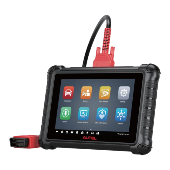
General Introduction This manual describes the construction and operation of the device and how it works to deliver diagnostic solutions. 2.1 MaxiCheck MX900 Tablet 2.1.1 Product Overview Figure 2-1 Tablet Front View 8.0” LCD Capacitive Touchscreen Ambient Light Sensor — detects ambient brightness. - Page 12 C. Red ⚫ Illuminates red when the tablet is powered on and the battery level is below 15% or an error has occurred. Figure 2-2 Tablet Back View Collapsible Stand — extends from the back to allow hands-free viewing of the tablet. Rear Camera Camera Flash Figure 2-3 Tablet Top View...
-
Page 13: Power Sources
2.1.2 Power Sources The tablet can receive power from any of the following sources: Internal battery pack ⚫ Vehicle power ⚫ External power supply ⚫ 2.1.2.1 Internal Battery Pack The tablet can be powered via the internal rechargeable battery, which if fully charged can provide sufficient power for about 7 hours of continuous use. -
Page 14: Other Accessories
Item Description 3.7 V/7700 mAh lithium-polymer battery ⚫ Power and Battery Charges via 5 V DC power supply ⚫ Tested Battery Life Around 7 hours of continuous use Battery Charging Input 5 V/3 A Approx. 600 mA (LCD on with default brightness, Power Consumption Wi-Fi on) @ 3.7 V Operating Temp. -
Page 15: Getting Started
Getting Started Ensure the tablet is sufficiently charged or is connected to an external power supply Power Sources (see 3.1 Power Up Press and hold the Power/Lock button on the top-right of the tablet to power on the unit. The power LED will illuminate green. The system boots up and displays the lock screen. Slide the Lock icon up to unlock. -
Page 16: Application Buttons
Accesses system software update menu. See Update. Remote Configures your unit to receive remote support using the Desktop TeamViewer application. See Remote Desktop. Manages the permissions for unlocking the OE gateway. Authorization Synchronizes Autel's online service database with the Support MaxiCheck tablet. See Support. -
Page 17: Locator And Navigation Buttons
Configures the tablet to operate as a video scope by MaxiVideo connecting to an imager head cable for close vehicle inspections. See MaxiVideo. Allows you to register an account, view and edit your Autel User personal profile and link your device. See Autel User Center Center. -
Page 18: System Status Icons
Button Name Description Chrome Launches the Google Chrome browser. Tap the Camera icon to open camera viewfinder. Press and hold the icon to take a screenshot of the Camera current screen. The saved files are saved in the Data Manager application for later review. See Data Manager for details. -
Page 19: Diagnostics
Diagnostics The Diagnostics application can access the electronic control unit (ECU) for various vehicle control systems, including engine, transmission, antilock brake system (ABS), and airbag system (SRS). 4.1 Getting Started Prior to first using of the Diagnostics application, ensure a communication link is established between the tablet and the test vehicle via the main cable. - Page 20 4.1.1.1 Top Toolbar Buttons The operations of the toolbar buttons at the top of the screen are listed and described in the table below: Table 4-1 Top Toolbar Buttons Button Name Description Home Returns to the MaxiCheck Job Menu. Tap to display a dropdown list: Tap Auto Detect for auto VIN detection.
-
Page 21: Vehicle Identification
4.2 Vehicle Identification The MaxiCheck diagnostics system supports five methods of Vehicle Identification. Auto Detect Manual Input Scan VIN/License Manual Vehicle Selection OBDII Direct Entry 4.2.1 Auto Detect The MaxiCheck diagnostics system features the latest VIN-based Auto Detect function to identify vehicles with just one tap, enabling you to quickly identify the exact vehicle and scan its available systems for fault codes. -
Page 22: Manual Input
4.2.2 Manual Input For vehicles that do not support the Auto Detect function, you may manually enter the vehicle VIN. ➢ To perform Manual Input Tap the Diagnostics application button from the MaxiCheck Job Menu. The Vehicle Menu displays. Tap the VID button on the top toolbar. Select Manual Input. -
Page 23: Manual Vehicle Section
Figure 4-3 Scan VIN/License If the VIN or license number cannot be scanned, you can input manually. Tap button on the bottom-right corner of the screen to display the screen for manually input. After entering the correct VIN, tap OK to continue. Follow the on-screen instructions to complete the operation and advance to the vehicle Diagnostics Menu screen. -
Page 24: Diagnostics Screen Layout
4.3 Diagnostics Screen Layout After the test vehicle is identified, the diagnostic menu will appear. This section consists of various commonly used functions, including Auto Scan and Control Unit. The available functions displayed vary depending on the test vehicle. Figure 4-4 Diagnostic Menu Screen The diagnostics screen typically includes four sections. - Page 25 Table 4-2 Diagnostics Toolbar Buttons Button Name Description Home Returns to the MaxiCheck Job Menu. Exits the diagnostics session of the currently identified Vehicle Swap test vehicle and returns to the vehicle menu screen. Settings Opens the Settings screen. See Settings.
-
Page 26: Screen Messages
Select a specific error, and a submission form will appear to let you enter the report information. Tap Send to submit the report via the Internet, and a confirmation message will appear when sent successfully. 4.3.1.2 Status Information Bar The Status Information Bar at the top of the Main Section displays the following items: Menu Title —... -
Page 27: Making Selections
4.3.2.3 Error Messages Error messages display when a system or procedural error has occurred. Possible errors include cable disconnection and communication interruption. 4.3.3 Making Selections The Diagnostics application is a menu-driven program that presents a series of options one at a time. As you select from a menu, the next menu in the series appears. Each selection narrows the focus and leads to the desired test. - Page 28 Figure 4-5 Auto Scan Screen Navigation Bar Main Section Function Buttons 4.4.1.1 Navigation Bar List Tab — displays the scanned data in list format. Progress Bar — indicates the test progress. 4.4.1.2 Main Section Column 1 — displays the system numbers. Column 2 —...
- Page 29 Table 4-3 Function Buttons in Auto Scan Name Description Report Displays the diagnostics data in a report. Erases all fault information after scanning. A warning message Quick Erase will display to inform you of possible data loss when this function is selected. Confirms the test result.
-
Page 30: Ecu Information
Available functions may vary by vehicle. The function menu may include: ECU Information — displays detailed ECU information. Select to view the ⚫ information screen. Trouble Codes — contains Read Codes and Erase Codes. The former displays ⚫ detailed DTC information retrieved from the vehicle control module, the latter allows you to erase DTCs and other data from the ECU. -
Page 31: Trouble Codes
Diagnostics Toolbar Buttons — see Table 4-2 Diagnostics Toolbar Buttons detailed descriptions for the operations for each button. Main Section — the left column displays the item names, and the right column shows the specifications or descriptions. Function Button — in this case, only the ESC button is available. Tap it to exit after viewing. -
Page 32: Live Data
Function Button Freeze Frame — tap to view the freeze frame data. ⚫ Search — tap to search related fault code information on the Internet. ⚫ Erase Codes — tap to erase the fault codes. ⚫ ESC — tap to return to the previous screen or exit the function. ⚫... - Page 33 Figure 4-9 Live Data Screen Diagnostics Toolbar Buttons — tap the drop-down button at the top center of the screen and the toolbar buttons will display. See Table 4-2 Diagnostics Toolbar Buttons for details. Main Section Name Column — displays the parameter names. ⚫...
- Page 34 Figure 4-10 Display Mode Screen Each parameter item displays its selected mode independently. ◆ Analog Gauge Mode — displays the parameters in gauge charts. ◆ Text Mode — the default mode that displays the parameters as a text list. NOTE Status parameters, such as a switch reading like ON, OFF, ACTIVE, and ABORT, can only be displayed in Text Mode.
- Page 35 Figure 4-11 Waveform Graph Mode Screen Settings Button (SetY) — sets the minimum and maximum values of the ⚫ Y axis. Scale Button — changes the scale values. ⚫ There are two scale buttons, displayed above the waveform graph to the right side, which can be used to change the scale values of the X axis and Y axis of the graph.
- Page 36 ➢ To edit the waveform color and line thickness in a data graph Select parameters to display in Waveform Graph mode. Tap the Edit Button, and an edit window will appear. The parameter is selected automatically in the left column. Select a color from the second column.
- Page 37 Figure 4-13 Trigger Setting Screen Two buttons and two input boxes are available in the Trigger Settings screen. Trigger On — switches the trigger on and off. The trigger is ON by default. Buzzer Alarm — switches the alarm on and off. The alarm function makes a beeping sound to alert you when the data reading reaches the preset minimum or maximum values.
- Page 38 below: Cancel All — tap to cancel all selected parameters. Up to 50 parameters can be selected at one time. Show Selected/Show All — tap to switch between the two options. One displays the selected parameters, the other displays all available items. Graph Merge —...
-
Page 39: Active Test
Previous Frame — moves to the previous frame of frozen data. ⚫ Next Frame — moves to the next frame of frozen data. ⚫ Play/Pause — tap to play/pause the frozen data. ⚫ Resume — tap to exit the freeze data mode and return to live data display. ⚫... -
Page 40: Special Functions
monitoring the operation of the actuators. Such tests may include switching a solenoid, relay or switch, between two operating states. Selecting Active Test displays a menu of test options. Available tests vary by vehicle. Select a test from the menu options. Follow the instructions displayed on the screen to complete the test. -
Page 41: Function Descriptions
between an ECM and a diagnostic tool. Global OBD may use several different communications protocols. Select a specific protocol under the Protocol option. Wait for the OBDII Diagnostics Menu to appear. Select a function to continue. Supported functions may vary by vehicle. DTC &... - Page 42 Stored Codes ⚫ Stored codes are emissions-related DTCs from the ECU of the vehicle. OBDII/EOBD codes are prioritized according to their emissions severity, with higher-priority codes overwriting lower-priority ones. The priority of the code determines the illumination of the Malfunction Indicator Lamp (MIL) and the codes erase procedure. Manufacturers rank codes differently, so DTCs may vary by vehicle.
-
Page 43: Diagnostic Reports
This Drive Cycle — displays the status of monitors since the beginning of the current ⚫ drive cycle. 4.5.2.3 Live Data This function displays the real time PID data from the ECU. Displayed data includes analog and digital input and output, and system status information broadcast in the vehicle data stream. -
Page 44: Diagnostics Report Saving, Viewing, And Sharing
Pre-Scan Function ⚫ Select a vehicle button from the Vehicle Menu screen. Enter the maintenance order number in the pop-up box to scan and detect the whole vehicle. You can also add pictures to record the current condition of the vehicle. Once the pre-scan is completed, you are not allowed to perform pre-scan again, and the scan result cannot be modified. - Page 45 Figure 4-15 History Screen Select a record and tap the button on the upper-right corner. Figure 4-16 Historical Test Screen Tap Get Report. Enter the license plate and current mileage. Tap Save.
- Page 46 Via the Auto Scan function ⚫ Tap Auto Scan from the Diagnostic Menu screen. The tablet will scan the ECU automatically. Figure 4-17 Select Auto Scan Screen When the system scan is completed, tap Report from the function buttons at the bottom of the screen.
- Page 47 Once you saved the reports by tapping the Save All Data button, tap Data Manager > PDF to view these reports. Once you saved the reports by tapping the Get Report or Save Report button, tap Data Manager > Cloud Report to view these reports saved to the Autel cloud platform.
-
Page 48: Exiting Diagnostics
4.6.2.3 Diagnostics Report Cloud Sharing Tap Data Manager > Cloud Report to enter the Report List screen. Figure 4-20 Report List Screen NOTE Note that if the report displays , it means the report has been uploaded to the cloud successfully, and you can share the report with others;... - Page 49 ➢ To exit the Diagnostics application On an active diagnostic screen, tap the Back or ESC function button to exit a diagnostic session; Or Tap the Vehicle Swap button in the diagnostics toolbar to return to the Vehicle Menu screen. On the Vehicle Menu screen, tap the Home button on the top toolbar;...
-
Page 50: Service
Service The Service application is specially designed to provide quick access to the vehicle systems for various scheduled service and maintenance tasks. The typical service operation screen is a series of menu-driven commands. Follow the on-screen instructions to select appropriate options, enter values or data, and perform necessary actions. -
Page 51: Epb Safety
⚫ been completed. NOTE Autel accepts no responsibility for any accident or injury arising from the maintenance of the EPB system. 5.3 Battery Management System (BMS) Service The BMS (Battery Management System) allows the tool to evaluate the battery charge state, monitor the closed-circuit current, register the battery replacement, and activate the rest state of the vehicle. -
Page 52: Steering Angle Sensor (Sas) Service
⚫ part of the steering system may have occurred NOTE AUTEL accepts no responsibility for any accident or injury arising from servicing the ⚫ SAS system. When interpreting DTCs retrieved from the vehicle, always follow the manufacturer’s recommendation for repair. -
Page 53: Tire Pressure Monitor System (Tpms) Service
to the DPF light and "Check Engine" indicators. A service regeneration can be requested in the workshop using the diagnostic tool. Before performing a forced DPF regeneration using the tool, check the following items: The fuel light is not on. ⚫... - Page 54 As an anti-theft device, an immobilizer disables one of the systems needed to start a car's engine, usually the fuel supply or the ignition. This is accomplished by radio frequency identification between a transponder in the ignition key and a device called a radio frequency reader in the steering column.
-
Page 55: Data Manager
Data Manager The Data Manager application allows you to store, print, and review the saved files, manage the workshop information, customer information records and keep test vehicle history records. Selecting the Data Manager application opens the file system menu. There are nine main functions available. -
Page 56: Vehicle History
Button Name Description Tap to review the saved reports and share Cloud Report cloud reports. Tap to review the reports stored as PDF format. Review Data Tap to review the recorded data. Tap to review the communication data and ECU information of the test vehicle. The Data Logging saved data can be reported and sent to the technical center via the Internet. -
Page 57: Historical Test Record
➢ To activate a test session for the recorded vehicle Tap Data Manager on the MaxiCheck Job Menu. Select Vehicle History to open the screen. Tap Diagnostics or Service to select diagnostic test records or service test records. Tap the Diagnostics icon at the bottom of the thumbnail of a vehicle record. The Diagnostics screen of the vehicle will appear and a new diagnostic session will be activated. -
Page 58: Workshop Information
➢ To edit the Test History Tap Data Manager on the MaxiCheck Job Menu. Select Vehicle History. Select the specific vehicle record thumbnail from the main section. The vehicle test record sheet will appear. Tap Edit (a pen icon) to edit the record. Tap each item to enter information or attach data files or images. -
Page 59: Customer
➢ To edit your Workshop Information Tap the Data Manager application on the MaxiCheck Job Menu. Select Workshop Information. Tap on each field to enter information. Tap Done to save the updated workshop information record, or tap Cancel to exit without saving. 6.3 Customer The Customer function allows you to create and edit customer accounts. -
Page 60: Image
➢ To delete a customer account Tap Data Manager on the MaxiCheck Job Menu. Select Customer. Tap the Delete icon on the right of a customer account. A message displays. Tap OK to confirm the command, and the account is deleted, or tap Cancel to cancel the request 6.4 Image The Image section is a database containing all captured screenshots. -
Page 61: Cloud Report
6.5 Cloud Report This section displays the saved reports, which can be transferred to the Autel cloud platform once a stable network connection is established. These reports can then be viewed or shared with others. See... -
Page 62: Review Data
6.7 Review Data The Review Data section allows you to play back recorded data frames of live data streams. On the Review Data main screen, select a record file to play back. Figure 6-6 Data Playback Screen Main Section — displays the recorded data frames. Navigation Toolbar —... -
Page 63: Settings
Settings Selecting Settings application opens a setup screen, on which you can adjust default settings and view information about the MaxiCheck system. The following options are available for the MaxiCheck system settings: Unit ⚫ Language ⚫ Printing Settings ⚫ Report Settings ⚫... -
Page 64: Language
Download the Maxi PC Suite software from www.autel.com > Support > Downloads > Autel Update Tools, and install it to your windows-based PC. Double click on Setup.exe. Select the installation language and the wizard will load momentarily. Follow the instructions on the screen and click Next to continue. -
Page 65: Report Settings
NOTE The MaxiSys Printer runs automatically after the installation. The PC, printer, and the tablet must be connected to the same network. This section describes how to receive files from the tablet and perform printing through the PC. NOTE Make sure the tablet is connected to the same network with your PC, either via Wi- ⚫... -
Page 66: Push Notifications
appears blue if the function is enabled and displays gray if the function is disabled. NOTE Make sure the tablet is connected to network while uploading reports. 7.5 Push Notifications This option allows you to manage notifications. The Notification Preferences option is turned on by default and cannot be turned off by users so that certain system notifications such as system security warnings will not be blocked. -
Page 67: Auto Update
Figure 7-1 Firmware Upgrade Screen ➢ To upgrade the firmware Connect the tablet to the vehicle using the main cable. Tap Settings on the MaxiCheck Job Menu. Tap Firmware Upgrade on the left column. Tap the Update Now button to upgrade the latest firmware version. Tap the Home button on the top-left corner to return to the MaxiCheck Job Menu, or select another setting option for system setup. -
Page 68: Vehicle List
7.8 Vehicle List This option allows you to sort the vehicles either by alphabetic order or by using frequency. ➢ To adjust the vehicle list setting Tap Settings on the MaxiCheck Job Menu. Tap Vehicle List on the left column. Select the desired sort order. -
Page 69: Update
Internet. Any updates that are found can be downloaded and installed on the device. This section describes installing an update to the MaxiCheck system. NOTE Ensure the tablet is registered before utilizing the Update application. See Autel User Center for a comprehensive registration guide. ➢ To update the software Power up the tablet, and ensure that it is connected to a power source and has a steady Internet connection. -
Page 70: Remote Desktop
You can use the application to receive remote support from Autel’s support center, colleagues or friends, by allowing them to control your MaxiCheck tablet on their PC via the TeamViewer software. - Page 71 Your partner must install the Remote Control software to their PC by downloading TeamViewer program (full version) online (see http://www.teamviewer.com), and then launch the software. Provide your ID to the partner and wait for them to send you a remote control request.
-
Page 72: Support
Support This application launches the Support platform which synchronizes Autel’s online service base station with the MaxiCheck tablet. Connected to Autel’s service channel and online communities, the Support application provides the quickest way for problem solutions, allowing you to send help requests to obtain direct service and support. -
Page 73: Data Logging
Tap Send to deliver your message to Autel support. 10.4 Training The Training section provides quick links to Autel’s online video library. Select a video channel by language to see all available online tutorial videos on topics such as product usage techniques and vehicle diagnostics practice. -
Page 74: Quick Link
Quick Link The Quick Link application provides you with convenient access to Autel’s official website and many other well-known sites in automotive service industry to provide technical help, knowledge bases, forums, and training and expertise consultations. Figure 11-1 Quick Link Screen ➢... -
Page 75: Maxiviewer
MaxiViewer The MaxiViewer application allows you to search the functions supported by our tools and the version information. There are two ways of searching, either by searching the product and the vehicle or searching the functions. ➢ To Search by the vehicle Tap the MaxiViewer application on the MaxiCheck Job Menu. - Page 76 Figure 12-2 Function Viewer Screen 2 ➢ To search by the functions Tap the MaxiViewer application on the MaxiCheck Job Menu. The Function Viewer screen displays. Tap the tool name on the top-left to open the drop-down list. Tap the one you want to search.
- Page 77 NOTE Fuzzy search is supported, so type in part of the function you want to search can also find out all the related information.
-
Page 78: Maxivideo
MaxiVideo The MaxiVideo application configures the MaxiCheck tablet to operate as a digital video scope by simply connecting the tablet to a MaxiVideo Digital Inspection Camera. This function allows you to examine difficult-to-reach areas normally hidden from sight, with the ability to record digital still images and videos, which offers you an economical solution to inspect machinery, facilities, and infrastructure in a safe and quick way. -
Page 79: Autel User Center
Figure 14-1 Autel User Center Screen If you already have an Autel ID, you can log in with your phone number and verification code, or tap Log In with Password to log in with your Autel ID and password. If you don't have an Autle ID yet, tap Register to create an Autel ID. - Page 80 If you have an Autel account, sign in with your account ID and password and skip to step 7. If you are a new member to Autel, click the Register button to create your Autel Enter the required personal information in the input fields.
-
Page 81: Maintenance And Service
Maintenance and Service To ensure that the MaxiCheck diagnostic tablet performs at its optimum level, we advise that the product maintenance instructions covered in this section is read and followed. 15.1 Maintenance Instructions The following shows how to maintain your devices, together with precautions to take. Use a soft cloth and alcohol or a mild window cleaner to clean the touchscreen of ⚫... -
Page 82: About Battery Usage
Your device may have not been connected to the charger properly. Check the ⚫ connector. NOTE If your problems persist, please contact Autel’s technical support personnel or your local selling agent. 15.3 About Battery Usage Your tablet is powered by a built-in Lithium-ion Polymer battery. This means that, unlike other forms of battery technology, you can recharge your battery while some charge remains without reducing your tablet’s autonomy due to the “battery memory effect”... -
Page 83: Service Procedures
15.4.1 Technical Support If you have any question or problem on the operation of the product, please contact us (see the following contact info) or your local distributor. Autel China Headquarters Phone: +86 (0755) 8614-7779 (Monday-Friday, 9AM-6PM Beijing Time) ⚫... - Page 84 ⚫ Address: 906-17, Preatoni Tower (Cluster L), Jumeirah Lakes Tower, DMCC, Dubai, ⚫ Web: www.autel.com ⚫ Autel Latin America Mexico: Phone: +52 33 1001 7880 (Spanish in Mexico) ⚫ Email: latsupport@autel.com ⚫ Address: Avenida Americas 1905, 6B, Colonia Aldrete, Guadalajara, Jalisco, ⚫...
-
Page 85: Repair Service
Web: www.autel.com/br ⚫ 15.4.2 Repair Service If it becomes necessary to return your device for repair, please download the repair service form from www.autel.com, and fill it in. The following information must be included: Contact name ⚫ Return address ⚫... -
Page 86: Compliance Information
Compliance Information FCC Compliance FCC ID: WQ8-DS900DV2231 This device complies with Part 15 of the FCC rules and Industry Canada’s license- exempt RSSs. Operation is subject to the following two conditions: This device may not cause harmful interference. This device must accept any interference received, including interference that may cause undesired operation. - Page 87 Changes or modifications not expressly approved by the party responsible for compliance could void the user’s authority to operate the equipment. The radiated output power of this device is below the FCC radio frequency exposure limits. Nevertheless, the device should be used in such a manner that the potential for human contact is minimized during normal operation.
-
Page 88: Warranty
Warranty 17.1 Limited One Year Warranty Autel Intelligent Technology Corp., Ltd. (the Company) warrants to the original retail purchaser of this MaxiCheck Diagnostic Device, that should this product or any part thereof during normal consumer usage and conditions, be proven defective in material... - Page 89 IMPORTANT All contents of the product may be deleted during the process of repair. You should create a back-up copy of any contents of your product before delivering the product for warranty service.
Need help?
Do you have a question about the MaxiCheck MX900 and is the answer not in the manual?
Questions and answers