Autel MaxiCOM MK808 Manual
Hide thumbs
Also See for MaxiCOM MK808:
- Manual (132 pages) ,
- Quick reference manual (2 pages) ,
- Manual (168 pages)
Table of Contents
Advertisement
Quick Links
Trademarks
®
®
®
®
®
®
Autel
,
MaxiSys
,
MaxiDAS
,
MaxiScan
,
MaxiTPMS
,
MaxiRecorder
,
and
®
MaxiCheck
are trademarks of Autel Intelligent Technology Corp., Ltd., registered in
China, the United States and other countries. All other marks are trademarks or
registered trademarks of their respective holders.
Copyright Information
No part of this manual may be reproduced, stored in a retrieval system or transmitted, in
any form or by any means, electronic, mechanical, photocopying, recording, or otherwise
without the prior written permission of Autel.
Disclaimer of Warranties and Limitation of Liabilities
All information, specifications and illustrations in this manual are based on the latest
information available at the time of printing.
Autel reserves the right to make changes at any time without notice. While information of
this manual has been carefully checked for accuracy, no guarantee is given for the
completeness and correctness of the contents, including but not limited to the product
specifications, functions, and illustrations.
Autel will not be liable for any direct, special, incidental, indirect damages or any
economic consequential damages (including the loss of profits).
IMPORTANT
Before operating or maintaining this unit, please read this manual carefully, paying
extra attention to the safety warnings and precautions.
For Services and Support
pro.autel.com
www.autel.com
1-855-288-3587/1-855-AUTELUS (North America)
0086-755-86147779 (China)
Support@autel.com
For technical assistance in all other markets, please contact your local selling agent.
i
Advertisement
Table of Contents

Related Manuals for Autel MaxiCOM MK808


Summary of Contents for Autel MaxiCOM MK808
- Page 1 All information, specifications and illustrations in this manual are based on the latest information available at the time of printing. Autel reserves the right to make changes at any time without notice. While information of this manual has been carefully checked for accuracy, no guarantee is given for the completeness and correctness of the contents, including but not limited to the product specifications, functions, and illustrations.
- Page 2 Safety Instructions The safety messages herein cover situations Autel is aware of. Autel cannot know, evaluate or advise you as to all of the possible hazards. You must be certain that any condition or service procedure encountered does not jeopardize your personal safety.
- Page 3 SAFETY WARNINGS Always perform automotive testing in a safe environment. Wear safety eye protection that meets ANSI standards. Keep clothing, hair, hands, tools, test equipment, etc. away from all moving or hot engine parts. Operate the vehicle in a well-ventilated work area, for exhaust gases are poisonous. ...
-
Page 4: Table Of Contents
CONTENTS USING THIS MANUAL ....................1 ..................... 1 ONVENTIONS Bold Text ...................... 1 Notes and Important Messages ..............1 Hyperlink ....................... 1 Illustrations ....................1 GENERAL INTRODUCTION ..................2 COM MK808 T ................... 2 ABLET Function Description ..................2 Power Sources ..................... 4 Technical Specifications ................ - Page 5 Making Selections ..................20 ......................21 IAGNOSIS Auto Scan ....................21 Control Unit ....................23 OBDII O ................32 ENERIC PERATIONS General Procedure ..................32 Function Descriptions ................. 34 ..................36 XITING IAGNOSTICS SERVICE OPERATIONS ....................37 ................... 37 ESET ERVICE (EPB) S ............
- Page 6 Data Logging ....................68 SETTINGS ........................69 ......................... 69 ......................70 ANGUAGE ................... 70 RINTING ETTINGS ..................... 71 EPORT ETTINGS ......................71 ULTITASK ..................71 IRMWARE PGRADE ....................72 PDATE ...................... 72 RDER ..................... 72 YSTEM ETTINGS ......................73 BOUT UPDATE ........................
- Page 7 Search Fix ....................86 Ask......................86 My MaxiFix ....................87 My Messages ..................... 88 Support ....................... 89 QUICK LINK ......................... 91 FUNCTION VIEWER ....................92 DIGITAL INSPECTION ....................94 .................. 94 DDITIONAL CCESSORIES Inspection Camera ..................95 ................95 MAGER CCESSORIES ..................
-
Page 8: Using This Manual
Using this Manual This manual contains device usage instructions. Some illustrations shown in this manual may contain modules and optional equipment that are not included in your system. Conventions The following conventions are used. Bold Text Bold text is used to highlight selectable items such as buttons and menu options. Example: ... -
Page 9: General Introduction
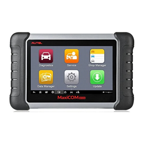
General Introduction When it comes to ultra-portability, MaxiCOM MK808 is your perfect companion. Installed with a fast quad-core processor, MK808 offers maximum convenience and swift diagnosis. The intuitive user screen makes using the device effortless through a 7-inch LCD touchscreen that displays at 1024 x 600 quality. Together with the ability to quickly... - Page 10 C. Red Illuminates red when the tablet is powered on and the battery level is below 15%. Figure 2-2 MaxiCOM MK808, Back View Collapsible Stand — extends from the back to allow hands-free viewing of the tablet. Heat Sink...
-
Page 11: Power Sources
Power Sources The tablet can receive power from any of the following sources: Internal Battery Pack Vehicle Power External Power Supply Internal Battery Pack The tablet can be powered with the internal rechargeable battery, which if fully charged can provide sufficient power for about 4.5 hours of continuous operation. -
Page 12: Technical Specifications
Technical Specifications Table 2-1 Specifications Item Description Recommended Use Indoor Operating System Android 4.4.4 Processor Cortex-A9 processor (1.5 GHz) Memory 64 GB 7-inch capacitive touchscreen with Display 1024x600 resolution Mini USB 2.0 USB 2.0 Connectivity Wi-Fi Micro SD card (supports up to 32 GB) Sensors Ambient light sensor for brightness auto adjust... -
Page 13: Accessory Kit
Item Description ISO9141-2, ISO14230-2,ISO15765, K/L-Line, Flashing Code, SAE-J1850 VPW, SAE-J1850 Supported Automotive PWM, ISO11898 (Highspeed, Middlespeed, Protocols Lowspeed and Singlewire CAN,fault-tolerant CAN), SAE J2610,GM UART,UART Echo Byte Protocol, Honda Diag-H Protocol, TP2.0, TP1.6 Accessory Kit Main Cable The Main Cable connects the tablet to the vehicle’s data link connector (DLC). Figure 2-4 Main Cable... -
Page 14: Other Accessories
Other Accessories Table 2-2 Other Accessories Mini USB Cable Connects the tablet to the PC or DC external power adapter. USB External Power Adapter Together with the mini USB cable, connects the tablet to the external DC power port for power supply. Quick Guide Device connection and diagnostics software update instructions. -
Page 15: Getting Started
Slide the Lock icon to the left to access the MaxiCOM Job Menu or slide to the right to unlock. Figure 3-1 Sample MaxiCOM MK808 Job Menu Application Buttons Locator and Navigation Buttons... - Page 16 See Settings. Checks for the latest update available for the Update MaxiCOM system, and performs updates. See Update. Launches Support platform which synchronizes Autel’s on-line service base Support station with MaxiCOM tablet. Support. Accesses technical tutorials and training...
-
Page 17: Locator And Navigation Buttons
Button Name Description Provides quick search for the supported Function functions and vehicles of Autel diagnostics Viewer tools. See Function Viewer. Configures the unit to operate as a video scope Digital device by connecting to an Imager head cable Inspection for close vehicle inspections. -
Page 18: System Status Icons
System Status Icons Tap on the bottom right corner to display Shortcuts Panel to set system settings of the tablet. Each icons function is described in the table below: NOTE The shortcuts buttons will be highlighted when enabled and dimmed when disabled. Table 3-3 Shortcuts Panel Buttons Button Name... -
Page 19: Diagnostics
Vehicle Menu Layout When the tablet is properly connected to the vehicle, the platform is ready to start vehicle diagnosis. Tap on the Diagnostics application button on the MaxiCOM MK808 Job Menu, the Vehicle Menu then displays. Figure 4-1 Sample Vehicle Menu... -
Page 20: Top Toolbar Buttons
Top Toolbar Buttons The operations of the toolbar buttons at the top of the screen are listed and described in the table below: Table 4-1 Top Toolbar Buttons Button Name Description Home Returns to the MaxiCOM Job Menu. Displays a dropdown list; tap Auto Detect for VIN Scan auto VIN detection;... -
Page 21: Vehicle Identification
Vehicle Identification The MaxiCOM diagnostics system supports four methods for Vehicle Identification. Auto VIN Scan Manual VIN Input Automatic Selection Manual Selection Auto VIN Scan The MaxiCOM diagnostics system features the latest VIN-based Auto VIN Scan function to identify vehicles with just one touch, enabling the technician to quickly identify the vehicle, san all the diagnosable ECUs on the vehicle and perform diagnostics on the selected system. - Page 22 Figure 4-3 Sample Auto VIN Screen 2 Review the information to ensure it is correct. Tap Yes to confirm the vehicle or NO if the information is not correct. Figure 4-4 Sample Vehicle Profile Screen The tool will establish communication with the vehicle to read control unit information.
-
Page 23: Manual Vin Input
Manual VIN Input For some vehicles that not supporting the Auto VIN Scan function, the MaxiCOM diagnostics system allows you to enter the vehicle VIN manually. To perform Manual VIN Input Tap the Diagnostics application button from the MaxiCOM Job Menu. The Vehicle Menu displays. -
Page 24: Manual Selection
To perform Automatic Selection Tap the Diagnostics application button from the MaxiCOM Job Menu. The Vehicle Menu displays. Tap the vehicle brand of the test vehicle. Tap Automatic Selection and the system will proceed to acquire the VIN. Follow the on-screen instruction to access the diagnostics screen. Manual Selection When the vehicle’s VIN is not automatically retrievable through the vehicle's ECU, or the specific VIN is unknown, you can choose to select the vehicle manually. - Page 25 Manager. Records the communication data and information of the test vehicle. The saved data can be reported and sent to Autel’s technical center via Data the Internet. Logging You can go to the Support application to follow up the processing progress, See Data Logging detailed information.
-
Page 26: Screen Messages
To print data in Diagnostics Tap the Diagnostics application button from the MaxiCOM Job Menu. The Print button on the diagnostics toolbar is available throughout the Diagnostics operations. Tap Print. A drop-down menu displays. Tap Print This Page to print a screenshot of the current screen. -
Page 27: Making Selections
4.3.2.1 Confirmation Messages This type of messages usually displays as an “Information” screen that informs you when you are about to perform an action that cannot be reversed or when an action has been initiated and your confirmation is needed to continue. When a user-response is not required to continue, the message displays briefly. -
Page 28: Diagnosis
Diagnosis The Diagnostics application enables a data link to the electronic control system of the test vehicle for vehicle diagnosis. The application performs functional tests, retrieves vehicle diagnostics information such as trouble and event codes and live data for various vehicle control systems, such as engine, transmission, and ABS. - Page 29 4.4.1.1 Navigation Bar List Tab — displays the scanned data in list format. Progress Bar — indicates the test progress. 4.4.1.2 Main Section Column 1 — displays the sequence numbers. Column 2 — displays the scanned systems. Column 3 —...
-
Page 30: Control Unit
Control Unit This option allows you to manually locate a required control system for testing through a series of choices. Follow the menu driven procedures and make proper selection each time; the program will guide you to the diagnostics function menu after selections are made. - Page 31 NOTE With the diagnostics toolbar on top of the screen throughout the whole diagnostics procedures, you are allowed to make various controls of the diagnostics information at any time, such as printing and saving the displayed data, getting help information, or performing data logging, etc.
- Page 32 4.4.2.2 Trouble Codes Read Codes This function retrieves and displays the DTCs from the vehicle’s control system. The Read Codes screen varies for each vehicle being tested. On some vehicles, freeze frame data can also be retrieved for viewing. The sample Read Codes screen displays as below: Figure 4-12 Sample Read Codes Screen Main Section Code Column —...
- Page 33 To erase codes Tap Trouble Codes from the Function Menu, then tap Erase Codes. A warning message displays to inform you of data loss if this function is completed. a) Tap Yes to continue. A confirming screen displays when the operation is successfully done.
- Page 34 To change the unit mode, tap the Setting button on the top toolbar and select a required mode. See Unit for more information. Display Mode There are four types of display modes available for data viewing, allowing you to view various types of parameters in the most suitable way.
- Page 35 Select a desired sample color from the middle column. Select a desired sample line thickness from the right column. Repeat steps 3-5 to edit the waveform for each parameter item. Tap Done to save the setting and exit, or tap Cancel to exit without saving. Function Buttons The operations of available function buttons on Live Data screen are described below:...
- Page 36 Figure 4-14 Sample Setting Mode in Live Data There are four navigation buttons on top of the Setting mode screen. Selected Button — displays the configuration screen on which you can set the threshold values, an upper limit and a lower limit, for triggering the buzzer alarm.
- Page 37 threshold lines are shown in different colors from the waveform of the parameters for distinction. Record Button — displays the configuration screen for Record Setting, on which you can set the trigger type, duration and trigger point for the data recording function.
- Page 38 Selecting Active Test opens a menu of test options that varies by make and model. Select a test from the menu options. Follow on-screen instructions to complete the tests. Procedures and instructions vary by vehicles. Some toggle and variable control tests display Active Test Controls at the top of the screen with data stream information below, or vice versa.
-
Page 39: Generic Obdii Operations
The main menu displays the supported special functions for the test vehicle. Follow the on-screen instructions to complete the tests. When the operation is done, an execution status message such as Completed, Finished or Successful displays. Tap the ESC button to exit the function. Figure 4-16 Sample Special Functions Screen Generic OBDII Operations A fast-access option for OBDII/EOBD vehicle diagnosis is available on the Vehicle Menu... - Page 40 communication between an ECM and a diagnostics tool. Global OBD may use several different communications protocols. Select a specific protocol under the Protocol option. Wait for the OBDII Diagnostic Menu to display. Figure 4-17 Sample OBDII Diagnostic Menu NOTE Tapping the button beside the function name to display additional function information.
-
Page 41: Function Descriptions
NOTE Some functions are supported only on certain vehicle manufacturers. Function Descriptions This section describes the various functions of each diagnostics option: 4.5.2.1 DTC & FFD When this function is selected, the screen displays a list of Stored Codes and Pending Codes. - Page 42 Freeze Frame In most cases the stored frame is the last DTC that occurred. Certain DTCs, which have a greater impact on vehicle emission, have a higher priority. In these cases, the top prioritized DTC is the one for which the freeze frame records are retained. Freeze frame data includes a “snapshot”...
-
Page 43: Exiting Diagnostics
4.5.2.7 Vehicle Status This item is used to check the current condition of the vehicle, including communication protocols of OBDII modules, amount of codes, status of the Malfunction Indicator Light (MIL), and additional information. Exiting Diagnostics The Diagnostics application remains open as long as there is active communication with the vehicle. -
Page 44: Service Operations
Service Operations The Service section is specially designed to provide you with quick access to the vehicle systems for various scheduled service and maintenance performances. The typical service operation screen is a series of menu driven executive commands. By following the on-screen instructions to select appropriate execution options, enter correct values or data, and perform necessary actions, the system will guide you through the complete performance for various service operations. - Page 45 NOTE For some vehicles, the scan tool can perform added functionality to reset additional service lights (maintenance cycle, service interval). Using BMW as an example, its service reset function includes engine oil, spark plugs, front/rear brakes, coolant, particle filter, brake fluid, micro filter, vehicle inspection, exhaust emission inspection and vehicle check.
- Page 46 Figure 5-2 Sample Oil Reset Service Screen 1 On the next screen, the available items would be listed with three columns displayed: CBS value, availability, and service counter. Figure 5-3 Sample Oil Reset Service Screen 2 Tap on the value you want to reset and then tap the Reset button on the right bottom of the screen.
-
Page 47: Electronic Parking Brake (Epb) Service
Ensure that the EPB control system is reactivated after the maintenance work has been completed. NOTE Autel accepts no responsibility for any accident or injury arising from the maintenance of the Electronic Parking Brake system. To perform EPB functions Tap the Service application button from the MaxiCOM Job Menu. -
Page 48: Emf Start-Up
Figure 5-5 Sample EPB Function List Follow the step-by-step on-screen instruction to complete the service. Press OK button to exit. EMF Start-up This service function would start the parking brake, it must be conducted after the following repairs: Replacing an EMF control unit. ... - Page 49 Figure 5-7 Sample EMF Star-up Screen 2 A screen will display to remind you that the fault memory of the parking brake control unit will be deleted, press Continue to proceed or the Back button to exit. Figure 5-8 Sample EMF Star-up Screen 3 Follow the on-screen instructions to pull the parking brake button and wait for around 3 seconds until the parking brake is set.
-
Page 50: Bms
When the operation is successfully completed, a “Completed successfully” message will appear on the screen. Press OK to exit. The BMS (Battery Management System) allows the scan tool to evaluate the battery charge state, monitor the close-circuit current, register the battery replacement, and activate the rest state of the vehicle. - Page 51 Figure 5-9 Sample BMS Function List Tap on the desired service. In this example, Tap function 2 (F2) to choose the function Battery exchange history display. A notice screen displays. Figure 5-10 Sample BMS Screen 1 Read carefully the complete information and press Continue. Figure 5-11 Sample BMS Screen 2 Check the battery capacity and the battery replacement information displayed.
- Page 52 Figure 5-12 Sample BMS Screen 3 To register the battery replacement Tap on the appropriate step to complete. In our example, tap function 1 (F1) Register battery replacement. Figure 5-13 Sample BMS Screen 4 Read carefully the information on the screen. Scroll through lists to view all the functions.
- Page 53 Enter battery replacement: same capacity Enter battery replacement: different capacity Enter battery replacement: Changing from the normal lead-acid battery (white housing) to AGM battery (black housing) Figure 5-15 Sample BMS Screen 6 Read carefully the information on the screen and tap Yes to continue. Follow the on-screen instructions to input the data matrix code of the newly installed battery that should be on the label of the battery.
-
Page 54: Steering Angle Sensor (Sas) Service
When the battery exchange is successfully entered, tap Continue to exit. Figure 5-17 Sample BMS Screen 8 Steering Angle Sensor (SAS) Service Steering Angle Sensor Calibration permanently stores the current steering wheel position as the straight-ahead position in the steering angle sensor EEPROM. Therefore, the front wheels and the steering wheel must be set exactly to the straight-ahead position before calibration. -
Page 55: Steering Angle Sensor Calibration
NOTE AUTEL accepts no responsibility for any accident or injury arising from servicing the SAS system. When interpreting DTCs retrieved from the vehicle, always follow the manufacturer’s recommendation for repair. All software screens shown in this manual are examples, actual test screens may vary for each vehicle being tested. - Page 56 Figure 5-19 Sample SAS Function Screen 1 A confirmation message will display when the operation is complete. A message will display if operation could not be completed because of an existing issue. Repair problem after exiting the diagnostics application. Figure 5-20 Sample SAS Function Screen 2...
-
Page 57: Dpf Service
DPF Service The DPF function allows you to carry out numerous functions to the Diesel Particulate Filter system. The tool will manage DPF regeneration, DPF component replacement teach-in and DPF teach-in after replacing the engine control unit. The ECM monitors driving style and selects a suitable time to employ regeneration. Cars driven primarily at idling speed and low load will attempt to regenerate earlier than cars driven with higher loads and at higher speed. -
Page 58: Diesel Particulate Filter: Replacement
Figure 5-21 Sample DPF Service Function Menu Diesel Particulate Filter: Replacement This function enable you to reset the adaptation values. Tap Diesel Particulate Filter: Replacement from the service functions menu to enter the service screen. Read carefully the information on the screen and press Continue. Figure 5-22 Sample Diesel Particulate Filter Screen 1... - Page 59 Tap function 1 (F1) to reset adaptation values for the particle filter. Figure 5-23 Sample Diesel Particulate Filter Screen 2 A confirmation message will display. Tap Yes to continue. Figure 5-24 Sample Diesel Particulate Filter Screen 3 The adaptation values are reset successfully. Tap Continue to end the service function.
-
Page 60: Diesel Particulate Filter: Request Regeneration
Diesel Particulate Filter: Request Regeneration This function is used to perform a regeneration run when some problems caused by a clogged Diesel Particulate Filter (DPF) happen. Available function options vary by vehicle. Tap Diesel Particulate Filter: Request Regeneration from the service functions menu. -
Page 61: Tire Pressure Monitor System (Tpms) Service
Figure 5-28 Sample Status Display Confirmation Screen Tire Pressure Monitor System (TPMS) Service The TPMS service function include displaying sensor IDs from the vehicle’s ECU, inputting TPMS sensor replacement IDs and testing sensors. Figure 5-29 Sample TPMS Function Menu Select Tire Pressure Sensor Replacement (Front left wheel sensor) as an example. - Page 62 NOTE This function will require the sensor ID be inputted on the screen. The sensor IDs can be read directly from the sensor or by using a sensor activation tool that can read the ID. Once the IDs have been entered, the vehicle may have to be driven at a certain speed for a certain time to complete procedure.
-
Page 63: Immo Service
For other services, please follow the on-screen instructions to operate. On completion of the drive cycle, carry out the tire pressure monitor system test application. IMMO Service An immobilizer is an anti-theft mechanism that prevents an automobile’s engine from starting if the correct ignition key is not used or other device is present. This device prevents thieves from starting the vehicle by a method known as hot wiring. - Page 64 Figure 5-32 Sample IMMO Note Screen Figure 5-33 Sample Program Key FOB Screen...
-
Page 65: Shop Manager
Shop Manager The Shop Manager application manages the workshop information including customer information records and test vehicle history records. There are three main functions available: Vehicle History Workshop Information Customer Manager The operations of these functions of the Shop Manager application are controlled by the toolbar buttons, which are listed and described in the table below: Table 6-1 Top Toolbar Buttons in Shop Manager Button... -
Page 66: Vehicle History
Vehicle History This function stores test vehicle history records, including vehicle information and the retrieved DTCs from previous diagnostics sessions. All information is displayed in summarized details. Tap on a record to resume a diagnostics session on a “stored vehicle”. ①—... - Page 67 Figure 6-2 Sample Historical Test Record Sheet To edit the Historical Test record sheet Tap the Shop Manager application on the MaxiCOM Job Menu. Tap Vehicle History. Select the specific vehicle history record thumbnail from the main section. The Historical Test record sheet displays.
-
Page 68: Workshop Information
Workshop Information Use the Workshop Information form to edit, input and save the detailed workshop information, such as shop name, address, phone number and other remarks, which when printing vehicle diagnostics reports and other associated test file, will display as the header of the printed documents. - Page 69 Choose Photo to choose from an existing images. If a customer adds or changes vehicles, tap Add New Vehicle Information, ○ and input the vehicle information. Tap the x button to cancel. Tap Done to save the account, or tap Cancel to exit without saving. ...
-
Page 70: Data Manager
Data Manager The Data Manager application is used to store, print, and review the saved files. Most operations are controlled through the toolbar. Selecting the Data Manager application opens the file system menu. Different file types are sorted separately under different options, there are seven types of information files to be viewed or played back. - Page 71 Figure 7-2 Sample Image Screen Toolbar Buttons — used to edit, print and delete the image files. See the following table for detailed information. Main Section — displays the stored images. Table 7-1 Toolbar Buttons in Image Button Name Description Back Returns to the previous screen.
-
Page 72: Report
Tap Image to access the image database. Select an image to display in full screen. Tap the screen to display the editing toolbar. Tap the Info button to display image information. Tap the Edit button on the top right corner of the window. The editing screen displays. -
Page 73: Pdf
Tap a report record to display the Report sharing dialog box. Figure 7-4 Sharing Report Screen 1 Tap View local reports to display it in full screen. Return to the Report List screen, tap the report and tap Report cloud sharing. Scan the QR code or tap Send Email or Send SMS to share the report. -
Page 74: Apps Uninstall
Figure 7-6 Sample Data Playback Screen Drop-down Toolbar — tap the button at the top center of the screen to open the Drop-down Toolbar. Main Section — displays the recorded data frames. Navigation Toolbar — allows you to manipulate data playback. Use the Navigation Toolbar buttons to playback the record data from frame to frame. -
Page 75: Vehicle Management
Vehicle Management The Vehicle Management section allows you to transfer the vehicle data to an external memory card to save memories of the tablet. Figure 7-7 Sample Vehicle Management Screen Data Logging The Data Logging section allows you to launch Support platform to view all records of all sent or unsent (saved) data logs on the diagnostics system. -
Page 76: Settings
Settings Selecting Settings application opens a setup screen to adjust the default setting and view information about the MaxiCOM system. The following shows options available for the MaxiCOM system settings: Unit Language Printing Settings Report Settings ... -
Page 77: Language
To install the printer driver Download the Maxi PC Suite from www.autel.com > Support > Downloads > Diagnostic Tool and install to your PC. Double click the setup.exe file. Select the installation language and the wizard will load momentarily. -
Page 78: Report Settings
If the Auto Print option on the MaxiSys Printer tab is selected, the received file is automatically printed. If the Auto Print option is not selected, click Open PDF File to view files. Select the file(s) to print and click Print. Report Settings This option automatically synchronizes the diagnostics information of the vehicle to the vehicle history and forms a diagnostics report for user to upload. -
Page 79: Auto Update
Auto Update The Auto Update allows the tool to automatically update the operating system, the MaxiCOM system and vehicle software. Tap the button on the right side of each software update to perform and set the time the automatic update should be done. ... -
Page 80: About
Mark the checkbox beside “Always show the App Switcher” on the right side of the screen. The App Switcher icon displays. Short press the App Switcher icon to open a control panel: Tap a specific app shortcut button to be directed to the selected application screen. ... -
Page 81: Update
Update The Update application allows you to download the latest released software. The updates can improve the MaxiCOM applications’ capabilities, typically by adding new tests, new models, or enhanced applications. The tablet automatically searches for available updates for the MaxiCOM software when it is connected to the internet. - Page 82 Middle Column — displays a synopsis of the changes to the software. Tap the button to open an information screen to view details. Tap outside the information screen to close it. Right Column — controls software update. According to the status of the ...
-
Page 83: Support
If you already have an Autel account, sign in with your account ID and password, and skip to step 9. If you are a new member to Autel, click Register on the left side of the screen to create your Autel ID. -
Page 84: Support Screen Layout
Personal Info The User Info and Device Info are both included under the Personal Info section. User Info — displays detailed information of your registered on-line Autel account, such as your Autel ID, Name, Address and other contact information. ... -
Page 85: Update Info
The Communities section launches and synchronizes with the Technical Forums on Autel’s official website www.autel.com. The community’s forum allows for discussion of technical issues, the sharing of information or tips with other members in Autel’s online support communities. Figure 10-2 Sample Communities Home Screen ... -
Page 86: Data Logging
Stuff — displays a list of your posts in the various forums. Training The Training section provides quick links to Autel’s online video accounts. Select a video channel by language to see all the available online tutorial videos. -
Page 87: Faq
The FAQ section provides comprehensive answers to the most frequently asked questions about member accounts and online subscription purchases. Account — displays questions and answers about the use of Autel’s online user account. Shopping & Payment — displays questions and answers about online subscription... -
Page 88: Academy
Academy Autel provides various tutorials and technical bulletins written by top-notch technicians and product experts. Please review the materials on the tablet or view additional technical articles on the online forum by clicking on click on the links provided. -
Page 89: Remote Desk
The Remote Desk application launches the TeamViewer Quick Support program, a simple, fast and secure remote control screen. Use this application to receive ad-hoc remote support from Autel’s support technicians by allowing them to control your MaxiCOM tablet on their PC via the TeamViewer software. -
Page 90: Maxifix
MaxiFix The MaxiFix application launches the on-line troubleshooter database, which not only provides you virtually all common diagnostics trouble code (DTC) database for most vehicles, but also serves as a forum allowing for technicians to network with other MaxiCOM users, and gives you access to a vast database of repair and diagnostics tips along with proven filed fixes. -
Page 91: The Header
The Header The Header at the top of the screen features: A Select Vehicle button to open the vehicle identification window, and vehicle information bar, for example “2014 > Hyundai > Accord Coupe > L4-2.4L (K24W1)”. A search field to find relevant information by entering keywords, codes, or problems. Select Vehicle Button The “Select Vehicle”... -
Page 92: Operations
Select the make of the vehicle from the list. Select the model of the vehicle from the list. Select the submodel of the vehicle from the list. Select the engine of the vehicle from the list. After completing the vehicle selection, the chosen vehicle is shown in the Header. Enter a Search Term. -
Page 93: Home
My MaxiFix — displays all your posts including Questions and Fixes in the community, and allows you to view your personal profile, select your vehicle preference, and share your tips. My Messages — shows a list of message notifications that are relevant to your activities in the Question section. -
Page 94: My Maxifix
Marked Posts — opens a list with links to Tips and discussions that you are actively participating in. My Profile — allows you to view your Autel account information including: your Autel ID, personal information, MaxiFix score, phone number and register time, and add an avatar image. -
Page 95: My Messages
13.2.4.1 Create a Tip A “Tip” is a concise and complete description of the fix for a particular vehicle repair issue. To create a new MaxiFix Tip Select My MaxiFix from the Navigation Menu. Select Select Vehicle from the Header and enter the identifying attributes of the vehicle you are writing the Tip about. -
Page 96: Support
13.2.5.1 Select “Adopted Answers” Members should select one Adopted Answer from responses on the “My Messages” screen before closing a question. Community members who provided the Adopted Answer are rewarded with scores for their contribution. About Adopted Answer: Only one answer can be selected as “Adopted Answer”. ... - Page 97 A contact email address A contact phone number...
-
Page 98: Quick Link
Quick Link The Quick Link application provides access to Autel’s official website and to other popular automotive service websites. These sites are invaluable resources of automotive information and repair data and include forums, video training and expert consultation. Figure 14-1 Sample Quick Link Screen ... -
Page 99: Function Viewer
Function Viewer The Function Viewer allows you to search the supported functions. There are two ways of searching, by vehicle or by function. To search by the vehicle Tap the Function Viewer application on the MaxiCOM Job Menu. The Function Viewer application screen displays. - Page 100 To search by the functions Tap the Function Viewer application on the MaxiCOM Job Menu. The Function Viewer application screen displays. Tap the tool name on the top left to drop down the tool list, tap the one you want to search.
-
Page 101: Digital Inspection
Digital Inspection The Digital Inspection application configures the MaxiCOM Diagnostics Device to operate as a digital video scope by simply connecting the tablet to a Digital Inspection Camera. This function allows you to examine difficult-to-reach areas normally hidden from sight, with the ability to record digital still images and videos, which offers you an economical solution to inspect machinery, facilities, and infrastructure in a safe and quick way. -
Page 102: Inspection Camera
Inspection Camera Figure 16-1 Digital Inspection Camera ① Removable Imager Head Cable — connects to the tool when performing inspection for image and video viewing. ② Handgrip — ergonomically designed handle for comfortable grip and agile operation. ③ USB Cable — connects the Camera to the MaxiCOM tablet. Imager Head Accessories Figure 16-2 8.5 mm Imager Head Accessories ①... -
Page 103: Accessory Assembly
Figure 16-3 5.5 mm Imager Head Accessories ① Mirror — helps to look around corners and see the unreachable areas. ② Magnet — picks up small metal objects, such as dropped rings or screws. Accessory Assembly 8.5 mm Imager Head The three accessories, including the Magnet, Hook, and Mirror, can be attached to the Imager Head in the same manner described below: Hold the accessory and the imager head. -
Page 104: Technical Specifications
Hold the accessory and the imager head. Screw the thread part of the accessory over the imager head to fix the accessory. Technical Specifications Table 16-1 Technical Specifications Item Description 0.79 to 2.36" (2 to 6 cm) with 8.5 mm-diameter imager head Optimal Viewing ... -
Page 105: Operations
Operations Before opening the Digital Inspection application, the imager head cable must be connected to the tablet using the USB cable. Install the correct imager head accessories according to the specific needs. NOTE When in operation, the imager head cable can be manipulated so as to better access confined or awkward spaces. - Page 106 Select the corresponding button on the upper-right corner to search or delete a video.
-
Page 107: Maintenance And Service
Maintenance and Service Maintenance Instructions The following shows how to maintain your devices, together with precautions to take. Use a soft cloth and alcohol or a mild window cleaner to clean the touch screen on the tablet. Do not use any abrasive cleansers, detergent, or automotive chemicals to the tablet. ... -
Page 108: Troubleshooting Checklist
You may be attempting to use the device in an overly hot/cold temperature. Try changing the charging environment. Your device may have not been connected to the charger properly. Check the connector. NOTE If your problems persist, please contact Autel’s technical support personnel or your local selling agent. -
Page 109: About Battery Usage
About Battery Usage Your tablet is powered by a built-in Lithium-ion Polymer battery. This means that, unlike other forms of battery technology, you can recharge your battery while some charge remains without reducing your tablet’s autonomy due to the “battery memory effect” inherent in those technologies. -
Page 110: Service Procedures
Technical Support If you have any question or problem on the operation of the product, please contact us (see the following contact info) or your local distributor. AUTEL NORTH AMERICA Phone:1-855-AUTEL-US(288-3587) Monday-Friday 9am-6pm EST Website: www.autel.com Email: sales@autel.com;... -
Page 111: Repair Service
Address: Office 1006-1010, Cluster C, Fortune Tower, Jumeirah Lakes Tower (JLT), Dubai, U.A.E Repair Service If it becomes necessary to return your device for repair, please download the repair service form from www.autel.com, and fill it in. The following information must be included: Contact name ... -
Page 112: Compliance Information
Compliance Information FCC Compliance FCC ID: WQ8-1610MX808 This device complies with Part 15 of the FCC rules and Industry Canada’s license- exempt RSSs. Operation is subject to the following two conditions: This device may not cause harmful interference. This device must accept any interference received, including interference that may cause undesired operation. -
Page 113: Sar
The radiated output power of this device is below the FCC radio frequency exposure limits. Nevertheless, the device should be used in such a manner that the potential for human contact is minimized during normal operation. The exposure standard for wireless devices employs a unit of measurement known as the Specific Absorption Rate, or SAR. -
Page 114: Warranty
Warranty Limited One Year Warranty Autel Intelligent Technology Corp., Ltd. (the Company) warrants to the original retail purchaser of this MaxiCOM Diagnostics Device, that should this product or any part thereof during normal consumer usage and conditions, be proven defective in material...
Need help?
Do you have a question about the MaxiCOM MK808 and is the answer not in the manual?
Questions and answers