Table of Contents
Advertisement
Quick Links
Trademarks
®
®
Autel
, MaxiCOM
, MaxiDAS
are trademarks of Autel Intelligent Technology Corp., Ltd., registered in China, the United
States, and other countries. All other marks are trademarks or registered trademarks of their
respective holders.
Copyright Information
No part of this manual may be reproduced, stored in a retrieval system or transmitted in any
form or by any means electronic, mechanical, photocopying, recording, or otherwise without
the prior written permission of Autel.
Disclaimer of Warranties and Limitation of Liabilities
All information, specifications and illustrations in this manual are based on the latest
information available at the time of printing.
Autel reserves the right to make changes at any time without notice. While information of
this manual has been carefully checked for accuracy, no guarantee is given for the
completeness and correctness of the contents, including but not limited to the product
specifications, functions, and illustrations.
Autel will not be liable for any direct, special, incidental, or indirect damages, or for any
economic consequential damages (including lost profits) as a result of using this product.
IMPORTANT
Before operating or maintaining this unit, please read this manual carefully, paying extra
attention to the safety warnings and precautions.
For Services and Support:
pro.autel.com
www.autel.com
1-855-288-3587/1-855-AUTELUS (North America)
0086-755-86147779 (China)
support@autel.com
For details, please refer to the
®
®
, MaxiScan
, MaxiTPMS
Service Procedures
i
®
, MaxiRecorder
in this manual.
®
®
, and MaxiCheck
Advertisement
Table of Contents

Related Manuals for Autel MaxiCOM Ultra Lite


Summary of Contents for Autel MaxiCOM Ultra Lite
- Page 1 Autel will not be liable for any direct, special, incidental, or indirect damages, or for any economic consequential damages (including lost profits) as a result of using this product.
-
Page 2: Safety Instructions
The safety messages herein cover situations Autel is aware of at the time of publication. Autel cannot know, evaluate or advise you in regards of all possible hazards. You must be certain that any condition or service procedure encountered does not jeopardize your... - Page 3 DANGER When an engine is operating, keep the service area WELL VENTILATED or attach a building exhaust removal system to the engine exhaust system. Engines produce carbon monoxide, an odorless, poisonous gas that causes slower reaction time and can lead to serious personal injury or loss of life.
-
Page 4: Table Of Contents
CONTENTS ......................AFETY NFORMATION ...................... AFETY NSTRUCTIONS 1 USING THIS MANUAL ...................... 1 ......................1 ONVENTIONS 2 GENERAL INTRODUCTION ..................... 3 COM T ...................... 3 ABLET VCI — V ..........8 LASH EHICLE OMMUNICATION NTERFACE ...................... 10 CCESSORIES 3 GETTING STARTED ....................... 13 3.1 P ........................ - Page 5 6.6 I (IMMO) S ................... 82 MMOBILIZER ERVICE 6.7 S (SAS) S ..............82 TEERING NGLE ENSOR ERVICE 7 DATA MANAGER ......................84 7.1 V ...................... 85 EHICLE ISTORY 7.2 W ..................87 ORKSHOP NFORMATION 7.3 C ....................... 87 USTOMER 7.4 I ........................
- Page 6 14 QUICK LINK ........................ 121 15 MAXIVIEWER ......................122 16 MAXIVIDEO ........................ 124 16.1 A ..................124 DDITIONAL CCESSORIES 16.2 O ......................128 PERATIONS 17 USER FEEDBACK ...................... 130 18 MAINTENANCE AND SERVICE ................. 131 18.1 M ................. 131 AINTENANCE NSTRUCTIONS 18.2 T ................
-
Page 7: Using This Manual
Using This Manual This manual contains device usage instructions. Some illustrations shown in this manual may make reference to modules and optional equipment that are not included in your system. Conventions The following conventions are used: 1.1.1 Bold Text Bold text is used to highlight selectable items such as buttons and menu options. Example: ... - Page 8 Example: To use the camera: Tap the Camera icon. The camera screen opens. Focus the image to be captured in the viewfinder. Tap the camera icon on the right side of the screen. The viewfinder now shows the captured picture and auto-saves the taken photo. Tap the thumbnail image on the top-right corner of the screen to view the stored image.
-
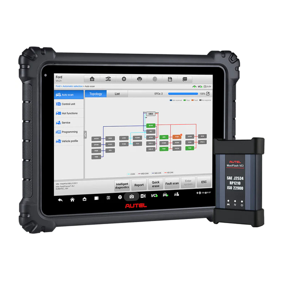
Page 9: General Introduction
General Introduction MaxiCOM Ultra Lite is a multi-platform diagnostics solution comprised of a powerful 12.9- inch TFT-LCD touchscreen Android-based tablet, a VCI communication and diagnostics unit, and an on-tool and cloud-based repair instructions and expert advice. As an intelligent diagnostics and information system, MaxiCOM Ultra Lite not only displays the relevant repairs gathered from experienced industry experts, but provides step-by-step guidance to ensure the repair is done correctly and efficiently. - Page 10 Table 2-1 Power LED Description Color Description Lights green when the tablet is charging and the battery level is above 90%. Green Lights green when the tablet is powered on and the battery level is above 15%. Power Lights yellow when the tablet is charging and the battery Yellow level is below 90%.
- Page 11 11. Mini USB Port — cannot be used with the USB Port simultaneously 12. USB Port 13. USB Port 14. Micro SD Card Slot 15. HDMI (High-Definition Multimedia Interface) Port 16. Head Phone Jack 17. DC Power Supply Input Port 18.
- Page 12 2.1.2 Power Sources The tablet can receive power from any of the following sources: Internal battery pack AC/DC power supply Vehicle utility power port IMPORTANT Do not charge the battery when the temperature is below 0 ° C (32 ° F) or above 45 ° C (113 °...
- Page 13 Item Description Wi-Fi x 2 (802.11 a/b/g/n/ac 2 x 2 MIMO) Bluetooth v.5.0 + EDR Connectivity USB 2.0 (two USB host Type A, one USB mini device) HDMI 2.0 SD card (supports up to 256 GB) ...
-
Page 14: Maxiflash Vci - Vehicle Communication Interface
MaxiFlash VCI — Vehicle Communication Interface 2.2.1 Function Descriptions Figure 2-5 MaxiFlash VCI Programming Device DC Power Supply Input Port Vehicle Data Connector Ethernet Port Vehicle LED Flashes green when the device is communicating with the vehicle system Connection LED ... - Page 15 IMPORTANT Do not disconnect the programming device while the vehicle LED status light is on! If the flash programming procedure is interrupted while the vehicle's ECU is blank or only partially programmed, the module may be unrecoverable. 2.2.1.1 Programming Capability The MaxiFlash VCI is a D-PDU, SAE J2534 &...
-
Page 16: Accessories Kit
Accessories Kit 2.3.1 Main Cable The VCI can be powered through the Autel Main Cable V2.0 (the V2.0 icon can be seen on the cable) when connected to an OBDII/EOBD compliant vehicle. The Main Cable connects the VCI to the vehicle's Data Link Connector (DLC), through which the VCI can... - Page 17 Figure 2-6 Main Cable — 1.5m in Length Note MaxiFlash VCI can be connected by the Autel Main Cable V2.0 only. DO NOT use other Autel main cables to connect the MaxiFlash VCI. 2.3.2 OBDI-Type Adapters (Optional) The optional OBDI-type adapters are for Non-OBDII vehicles. The adapter used depends on the type of vehicle being tested.
- Page 18 Auxiliary Power Outlet Adapter Supplies power to the tablet or the VCI through connection to the vehicle’s auxiliary power outlet, as some non-OBDII vehicles cannot provide power via the DLC connection. Clamp Cable Supplies power to the tablet or the VCI through connection to the vehicle battery.
-
Page 19: Getting Started
Getting Started Make sure the tablet has sufficient power or is connected to an external power supply (see Power Sources on page 6). NOTE The images and illustrations depicted in this manual may differ slightly from those in the most recent product. - Page 20 98. Assesses the Battery Test menu. See Battery Battery Test Test on page 104 for details. Synchronizes Autel's online service database with Support the MaxiCOM tablet. See Support on page 115. Configures your unit to receive remote support Remote using the TeamViewer application.
- Page 21 Button Name Description Provides a quick search for supported functions MaxiViewer and/or vehicles. See MaxiViewer on page 122. Configures the unit to operate as a video scope device by connecting to an imager head cable for MaxiVideo close vehicle inspections. See MaxiVideo on page 124.
-
Page 22: Power Down
Button Name Description Adjusts the brightness of the screen and the Display & Sound volume of the audio output. Opens the VCI Manager application. A green icon at the bottom-right corner indicates the VCI is connected, while a red “x” indicates no connection. - Page 23 To power down the MaxiCOM tablet Press and hold the Power/Lock button. Tap Power Off. Tap OK. 3.2.1 Reboot System In case of a system crash, long press the Power/Lock button and tap Reboot to restart the system.
-
Page 24: Diagnostics
Diagnostics The Diagnostics application can access the electronic control module of multiple vehicle control systems, including but not limited to the engine, transmission, anti-lock brake system (ABS), and airbag system (SRS). 4.1 Establish Vehicle Communication and Selection 4.1.1 Establish Vehicle Communication The Diagnostics operations require connecting the MaxiCOM tablet to the test vehicle through the VCI using the Main Cable V2.0 (Use the applicable OBDI-type adapter if needed). - Page 25 NOTE The vehicle's DLC is not always located under the dashboard. Refer to the user manual of the test vehicle for additional connection information. Non-OBDII Vehicle Connection This type of connection requires both the main cable and a required OBDI adapter for the specific vehicle being serviced.
- Page 26 After the VCI is properly connected to the vehicle, the Power LED on the VCI lights solid green, and is ready to establish communication with the tablet. The VCI device supplied with the MaxiCOM Ultra Lite tool kit supports three communication methods with the tablet: Bluetooth, Wi-Fi, and USB.
- Page 27 Wi-Fi Connection The VCI supports 5 GHz Wi-Fi connection. In open areas, the working range of 5G Wi-Fi communication is up to 164 feet (50 m). To pair the tablet with the VCI via Wi-Fi Power up the tablet. Select the VCI Manager application from the MaxiCOM Job Menu.
- Page 28 Move the tablet closer to the VCI. If using the wired connection, ensure the cable is securely attached to the VCI. Ensure the VCI communication mode is lit for the selected communication type: Bluetooth, Wi-Fi, or USB. B. If the VCI is unable to establish a communication link, troubleshooting instructions will appear.
- Page 29 Top toolbar Buttons The operations of the Toolbar buttons at the top of the screen are listed and described in the table below: Table 4-1 Top Toolbar Buttons Name Button Description Home Returns to the MaxiCOM Job Menu. Opens a dropdown list; tap Auto Detect for auto VIN detection;...
- Page 30 Auto VIN Scan Manual Input Scan VIN/License Manual Vehicle Selection OBDII Direct Entry 4.1.3.1 Auto VIN Scan The MaxiCOM diagnostics system features the latest VIN-based Auto VIN Scan function to identify test vehicles with just one tap, enabling the technician to quickly identify the exact vehicle and scan its available systems for fault codes.
- Page 31 Figure 4-4 Automatic Selection Screen 4.1.3.2 Manual Input For vehicles that do not support the Auto Scan function, the MaxiCOM diagnostics system allows you to enter the VIN or license number manually, or simply take a photo of the VIN sticker or license plate for quick vehicle identification.
- Page 32 Tap the icon on the top-right corner to exit Manual Input. 4.1.3.3 Scan VIN/License Tap Scan VIN/License in the dropdown list (Figure 4-3). The camera will be opened. On the right side of the screen, from top to bottom, three options are available: Scan Bar Code, Scan VIN, and Scan License.
- Page 33 Figure 4-7 Scan VIN Code Sample 2 4.1.3.4 Manual Vehicle Selection When the VIN is not automatically retrievable through the vehicle's ECU, or when the VIN is unknown, you can select the vehicle manually. Step-by-step Vehicle Selection This mode of vehicle selection is menu-driven. Select the Manufacturer icon on the Vehicle Menu screen to open the Vehicle Selection screen.
-
Page 34: Diagnostics Screen Layout
4.1.3.5 Alternative Vehicle Identification Occasionally, the tablet may not be able to identify a vehicle. For these vehicles, the user may perform a generic OBDII or EOBD diagnostics. See Generic OBDII Operations page 50 for additional information. 4.2 Diagnostics Screen Layout This section consists of various commonly used functions, including Auto Scan, Control Unit, and more. - Page 35 This function will record the communication data and ECU information of the test Data vehicle and send it to Autel technical staff to review Logging and provide a solution. Go to the Support application to view the processing progress.
- Page 36 NOTE Make sure the tablet and the printer are connected either by Wi-Fi or LAN before printing. For more instructions on printing, see Printing Settings on page 93 for details. To submit Data Logging reports in Diagnostics Tap the Diagnostics application button from the MaxiCOM Job Menu. The Data Logging button on the diagnostics toolbar is available throughout the Diagnostics operations.
- Page 37 The table below provides a brief description of how the function buttons operate. Table 4-3 Function Buttons in Diagnostics Screen Name Description Directly accesses the Intelligent Diagnostics screen to view the Intelligent code-related information of ALL DTCs for the whole vehicle. Diagnostics For detailed operation instructions, please refers to the Intelligent Diagnostics Operation...
-
Page 38: Auto Scan
Error Messages These appear when a systemic or procedural error has occurred. Possible errors include cable disconnection and communication interruption. 4.2.2 Making Selections The Diagnostics application is a menu-driven program that presents a series of options. As you select from a menu, the next menu in the series appears. Each selection narrows the focus and leads to the desired test. - Page 39 B. List Tab Page Figure 4-11 List Tab Page The Auto Scan function performs a comprehensive scan of all the systems in the vehicle ECU to locate faults and retrieve DTCs. Tap Fault Scan to start. Systems with no faults detected will appear in green;...
- Page 40 Figure 4-12 Vehicle Information Selection Screen The Topology tab page displays in the main section. Tap the Fault Scan button at the bottom of the screen to scan the vehicle system modules. Figure 4-13 Auto Scan Screen Sample 1 A system scanned with no faults detected appears in green; a system scanned with faults detected will appear in orange.
-
Page 41: Control Unit
Figure 4-14 Auto Scan Screen Sample 2 Select System On the Auto Scan screen, there is a Select System icon on the upper-right corner. Select the corresponding system(s) to scan, saving more time than scanning all systems. 4.4 Control Unit The Control Unit allows you to manually locate a required control system for testing through a series of choices. -
Page 42: Ecu Information
Available functions may vary by vehicle. The function menu may include: ECU Information — displays detailed ECU information. Select to display information screen. Trouble Codes — contains Read Codes and Erase Codes. The former displays detailed DTC information retrieved from the vehicle control module; the latter allows you to erase DTCs and other data from the ECU. -
Page 43: Trouble Codes
specifications or descriptions. 6. Function Button — in this case, only the ESC button is available. Tap it to exit after viewing. 4.6 Trouble Codes 4.6.1 Read Codes This function retrieves and displays DTCs from the vehicle control system. The Read Codes screen varies for each vehicle being tested. -
Page 44: Live Data
related repair cases and help information. Freeze Frame — a snowflake icon appears when freeze frame data is available for viewing; Tap to display data screen. The Freeze Frame interface is similar to that of the Read Codes interface and shares similar operations. Search —... - Page 45 Figure 4-18 Live Data Screen 1. Diagnostics Toolbar Buttons — see Table 4-2 Diagnostics Toolbar Buttons on page 29 for detailed descriptions of the operations of each button. 2. Current Directory Path 3. Status Information Bar 4. Navigation Bar 5. Main Section Name Column —...
- Page 46 Change button (for switching the unit of displayed data), and one Trigger button (tap to open the "Trigger Settings" window). Figure 4-19 Display Mode Screen Each parameter displays the selected mode independently. Analog Gauge Mode — displays the parameters in gauge charts. ...
- Page 47 Settings Button (SetY) — sets the minimum and maximum value of the Y-axis. Scale Button — changes the scale values. There are two scale buttons, displayed above the waveform graph to the right side, which can be used to change the scale values of the X-axis and Y-axis of the graph. There are four scales available for the X-axis: x1, x2, x4 and x8, and three scales available for the Y-axis: x1, x2, and x4.
- Page 48 5. Select a line thickness from the right column. 6. Tap Done to save the settings and exit, or tap Cancel to exit without saving. NOTE In full screen display mode, you can edit the waveform color and line thickness by tapping the Edit button on the top-right side of the screen.
- Page 49 To set a trigger Tap the drop-down button to the right of a parameter to open a submenu. Tap the Trigger button to the right of the submenu to open the Trigger Settings window. Tap the MIN input box and enter the minimum threshold value. Tap the MAX input box and enter the maximum threshold value.
- Page 50 Please select 2 to 5 of the supported parameters and tap the OK button to merge. Tap the Cancel Merge button at the bottom of the Live Data screen to cancel merge. To Top — moves a selected data item to the top of the list. ...
-
Page 51: Active Test
NOTE Only data recorded during the current operation can be reviewed on the Live Data screen. All historical recorded data can be reviewed in "Review Data" in the Data Manager application. Previous Frame — switches to the previous frame of recorded data. ... -
Page 52: Special Functions
screen. Follow the on-screen instructions and make appropriate selections to complete the tests. Tap the ESC function button to exit the test when finished. 4.9 Special Functions These functions perform various component adaptations, including the recalibration or configuration of certain components after repairs or replacements have been completed. Figure 4-24 Special Function Screen Sample 1 Select a function to display detailed function information and the execution screen. -
Page 53: Programming And Coding
Column 2 — displays the execution status such as Completed or Activated or may display live data values that correspond to the special function Column 3 — displays the measurement units of the live data Tap a function button to perform the selected function or exit the function. 4.10 Programming and Coding Since the introduction of OBDII and leading up to modern hybrids and EVs, hardware and software technologies in cars have been advancing at an exponential rate. - Page 54 Selecting the Programming or Coding function opens a menu of operation options that varies by vehicle make and model. Selecting a menu option either displays a programming interface or opens another menu of additional choices. Follow all screen instructions while performing the programming or coding operations.
- Page 55 Figure 4-26 Reprogramming Operation Screen Typical reprogramming operations require you to input and validate the VIN number first. Tap the input box and enter the correct number. The programming interface then appears. The main section of the reprogramming interface offers information about the hardware, the current software version and the newest software versions to be programmed into the control units.
-
Page 56: Generic Obdii Operations
4.11 Generic OBDII Operations The OBDII/EOBD vehicle diagnosis option offers a quick way to check for DTCs, isolate the cause of an illuminated malfunction indicator lamp (MIL), check monitor status prior to emissions certification testing, verify repairs, and perform other emissions-related services. - Page 57 I/M Readiness Live Data O2 Sensor Monitor On-Board Monitor Component Test Vehicle Information Vehicle Status NOTE Supported functions may vary by vehicle. 4.11.2 Function Descriptions This section describes the various functions of each diagnostics option: DTC &...
- Page 58 rank codes differently, so DTCs may vary by vehicle. Pending Codes These are codes whose storing conditions have been met during the last drive cycle, but need to be met on two or more consecutive drive cycles before the DTC stored. The purpose of displaying pending codes is to assist the service technician after a vehicle repair when diagnostics information is cleared, by reporting test results after a single driving cycle.
-
Page 59: Diagnostics Report
4.11.2.3 Live Data This function enables the display of real-time PID data from the ECU. Displayed data includes analog and digital input and output, and system status information broadcast in the vehicle data stream. Live data can be displayed in various modes. See Live Data on page 38 for detailed information. - Page 60 2. Print Pre-scan Report — vehicle images can be taken with tablet and attached to scan report. The report file can be generated and submitted. The report can be customized with shop and vehicle information. 3. Repair Vehicle — creates efficient repair plan from the start. 4.
- Page 61 Figure 4-30 Historical Test Screen b) Via the Report function: Tap Data Manager on the MaxiCOM Job Menu. Tap Report to open the report list. Figure 4-31 Report Screen Sample 1 Select a specific history record from the report list.
- Page 62 Figure 4-32 Report Screen Sample 2 View the local reports or share the report to Autel cloud. Figure 4-33 Report Screen Sample 3 Tap the ellipses button in the upper-right corner to save the report to the document...
- Page 63 Figure 4-34 Report Screen Sample 4 c) Via the Auto Scan function: Enter the Auto Scan page and tap Fault Scan in the Function Button Bar at the bottom of the screen. Figure 4-35 Auto Scan Screen Sample 1 ...
- Page 64 Figure 4-36 Auto Scan Screen Sample 2 Tap the button in the Diagnostics Toolbar, and select Save All Data to save the PDF document, select Take a Screenshot to save the screenshot of the current page, or select Save Report to save the vehicle test report. Figure 4-37 Auto Scan Screen Sample 3...
-
Page 65: Exit Diagnostics
Figure 4-38 PDF Document Screen d) Via the buttons on the Navigation Bar: The diagnostics report can also be viewed from the Auto Scan, Trouble Codes, Live Data, and Active Test screens. Tap the button in the Diagnostics Toolbar, and select Save All Data to save the PDF document. - Page 66 NOTE Damage to the vehicle electronic control module (ECM) may occur if communication is disrupted. Ensure all forms of communication links such as data cable, USB cable, and wireless or wired network, are properly connected throughout the test. Exit all interfaces before disconnecting the test cable and power supply.
-
Page 67: Intelligent Diagnostics
Intelligent Diagnostics Intelligent Diagnostics is a specific fault code analysis function, with which you can access the most comprehensive and the latest code-specific data, DTC analysis, repair assist, repair tips, and relevant repair cases. It has been drawn from actual shop repair orders and records and with input from experienced industry professionals. - Page 68 Figure 5-1 System List Screen For a number of vehicle brands, including Volkswagen, Audi, BMW, Ford, Land Rover, Jaguar, Chrysler, Fiat, Volvo, and more, a topology map is available to display the relationship among vehicle systems. Figure 5-2 Topology Display Screen Select the List tab to display the vehicle systems as a list.
- Page 69 Figure 5-3 List Screen 5.1.2 Scan System Faults Once the vehicle system listing or Topology mapping has been completed, tap the Fault scan button at the bottom of the System list, Topology or List screen to find the faults in the vehicle systems.
- Page 70 Figure 5-5 Fault Scan on System List Screen Sample 2 On the Topology screen, a system with identified faults will appear in orange, with the number of faults displayed in the upper-right corner of the system icon. The number of total faults will appear on the top. Figure 5-6 Fault Scan on Topology Screen On the List screen, a system with identified faults will also appear in red, with the number of faults on the right.
- Page 71 Figure 5-7 Fault Scan on List Screen After scanning system faults, there are two methods to access the Intelligent Diagnostics screen: Access via the Intelligent Diagnostics button to view code-related information of all DTCs for the whole vehicle. Access via the Intelligent Diagnostics icon to view code-related information of a specific DTC.
- Page 72 Figure 5-8 Intelligent Diagnostics Button Screen 5.1.4 Access via Intelligent Diagnostics Icon You can also use the Intelligent Diagnostics icon to enter the Intelligent Diagnostics function to get detailed fault repair instructions of a specific DTC. The details of the detected fault(s), including the fault code, fault description, and status, will be displayed right under the system name or module.
- Page 73 Diagnostics icon shown below. Tap the Intelligent Diagnostics icon to enter the Intelligent Diagnostics screen directly. Figure 5-10 Intelligent Diagnostics Icon Screen Sample 2 When entering a specific system by tapping the arrow-shaped icon , you can also access the Intelligent Diagnostics screen if the Intelligent Diagnostics function is available for this vehicle.
- Page 74 Figure 5-12 Entering System Icon Screen (Topology) Select Trouble codes from the Function menu screen and the trouble codes screen will appear. Figure 5-13 Function Menu Screen Tap the Intelligent Diagnostics icon to the right of the DTC description. Or select a specific DTC from the DTC list, and then tap the Intelligent Diagnostics button at the bottom of the screen.
-
Page 75: Intelligent Diagnostics Operation
Figure 5-14 Trouble Codes Screen 5.2 Intelligent Diagnostics Operation Intelligent Diagnostics is an important and powerful function of MaxiCOM Ultra Lite. It provides substantial information for intelligent diagnosis of the faults detected, offering Technical Service Bulletin, DTC Analysis, Repair Assist, Repair Tips, and Component Measurement to help you repair detected faults. - Page 76 The Intelligent Diagnostics function consists of the following sections: Vehicle System and Detected DTC(s) — displays the name of the vehicle system(s) and the detected DTC(s). Technical Service Bulletin — contains DTC-related recalls, TSB, and OEM campaigns. DTC Analysis — provides repair assistance information related to the fault code. Repair Assist —...
- Page 77 5.2.2 Technical Service Bulletin (OEM Information) The Technical Service Bulletin function matches the selected fault code with relevant vehicle manufacturer TSBs. All TSBs that relate to the selected DTC are listed in the TSB display window. Select a TSB to open the TSB page and view the TSB in details. Figure 5-17 TSB Screen Figure 5-18 TSB in Details 5.2.3 DTC Analysis...
- Page 78 Figure 5-19 DTC Analysis Screen 5.2.4 Repair Assist The Repair Assist displays a list of items and their descriptions, completion status, and priorities. The higher the priority number is (1 is the highest), the earlier the related items will be tested. ...
- Page 79 Figure 5-21 Repair Assist Screen Sample 2 Table 5-2 Completion Status in Repair Assist Button Name Description This indicates that all branches of the Completed procedure are completed. This indicates that certain branches of the Uncompleted procedure has not uncompleted. This indicates that no branch of the Not running procedure is running.
- Page 80 NOTE In some cases, you need to tap the right-arrow icon on the center divider to hide the right column so that the whole interface of Select Branch can be seen. In this repair process, it may integrate one or more diagnostics functions such as Read Codes, Erase Codes, Live Data, Freeze Frame and Active Test as needed.
- Page 81 Figure 5-25 Repair Assist Screen Sample 6 The instructions for using the Wiring Diagram are as follows: Figure 5-26 Repair Assist Screen Sample 7 ① Tap this button to search or tap a certain module name to locate it. After location, the related wires will be highlighted.
- Page 82 Figure 5-27 Repair Assist Screen Sample 8 Measure the resistance/voltage/current between the two pins according to the prompts in the multimeter to see if the measured value is correct or not. NOTE If you have connected to a VCMI device, tap the F1 button to start measurement directly. After the inspection finishes, a solution will be generated to guide you to solve the problem with some reference information.
- Page 83 Figure 5-29 Repair Tips Description 5.2.6 Component Measurement The component measurement section directs technicians to oscilloscope in one click. This section may include relevant waveforms and waveform analysis to aid the technician in diagnostics and repairs. Figure 5-30 Component Measurement Screen NOTE To run the oscilloscope for measuring components, connect the tablet to a VCMI device.
- Page 84 5.2.7 Relevant Cases This section offers recommended repair cases that may be relevant to the current vehicle and/or the current fault. These repair cases may provide greater insight into diagnosing and repairing your vehicle. Tap the relevant cases to review. ...
-
Page 85: Service
Service The Service section is designed to provide quick access to the vehicle systems for various scheduled service and maintenance tasks. The typical service operation screen is a series of menu driven executive commands. Follow on-screen instructions to select appropriate execution options, enter correct values or data, and perform necessary actions. -
Page 86: Electric Parking Brake (Epb) Service
Ensure that the EPB control system is reactivated after the maintenance work has been completed. NOTE Autel accepts no responsibility for any accident or injury arising from the maintenance of the Electric Parking Brake system. 6.3 Tire Pressure Monitoring System (TPMS) Service This function allows you to quickly look up the tire sensor IDs from the vehicle ECU, as well as to perform TPMS replacement and reset procedures after tire sensors are replaced. -
Page 87: Battery Management System (Bms) Service
6.4 Battery Management System (BMS) Service The Battery Management System (BMS) allows the tool to evaluate the battery charge state, monitor the close-circuit current, register the battery replacement, activate the rest state of the vehicle, and charge the battery via the diagnostics socket. NOTE This function is not supported by all vehicles. -
Page 88: Immobilizer (Immo) Service
IMPORTANT Before diagnosing the problem vehicle and attempting to perform an emergency regeneration, it is important to obtain a full diagnostics log and read out relevant measured value blocks. NOTE The DPF will not regenerate if the engine management light is on, or there is a faulty EGR valve. - Page 89 Accident repairs where damage to the SAS, SAS assembly, or any part of the steering system may have occurred NOTE Autel accepts no responsibility for any accident or injury arising from servicing the SAS system. When interpreting DTCs retrieved from the vehicle, always follow the manufacturer's recommendation for repair.
-
Page 90: Data Manager
Data Manager The Data Manager application allows you to store, print, and review saved files, manage workshop information, customer information records, and store test vehicle records. Selecting Data Manager opens the file system menu. There are nine main functions available. Figure 7-1 Data Manager Main Screen The table below describes each of the function buttons in Data Manager. -
Page 91: Vehicle History
Review Data View recorded data. Uninstall Uninstall applications. Apps View communications with Autel support service and ECU information for the test vehicle. The saved Data Logging data can be reported and sent to the technical center via the Internet. 7.1 Vehicle History This function stores vehicle test records, including vehicle information and the retrieved DTCs from previous diagnostics sessions. - Page 92 4. The Diagnostics screen of the vehicle displays and a new diagnostics session is activated. See Diagnostics for detailed instructions on vehicle diagnostics operations. 5. Select a vehicle thumbnail to select a record. A History Test record sheet appears. Review the recorded information of the test vehicle, and tap the Diagnostics button on the upper-right corner to continue diagnostics.
-
Page 93: Workshop Information
6. Tap Add a Customer to correlate the historical Records sheet to an existing customer account, or add a new account to be correlated with the test vehicle record. See 7.3 Customer on page 87 for more information. 7. Tap Done to save the updated record, or tap Cancel to exit without saving. NOTE The vehicle VIN, license number, and customer account are correlated by default. -
Page 94: Image
2. Select Customer. 3. Tap the Add a customer button. An empty information form displays. Tap each field to input the appropriate information. NOTE The items that must be filled are indicated as required fields. 4. For customers with more than one vehicle for service, tap Add New Vehicle Information. - Page 95 Figure 7-5 Image Database Screen 1. Toolbar Buttons — used to edit, print or delete stored image files. See Table 7-2 Toolbar Buttons Description on page 89 for detailed information. 2. Main Section — displays the stored images. Table 7-2 Toolbar Buttons Description Button Name Description...
-
Page 96: Report
Tap Email to send the selected image(s) to an email. 7.5 Report The Report section stores diagnostics reports. You can view local reports or share the report to Autel cloud after entering the report database and selecting a specific report. For more Report information, please refer to Diagnostics Report on Page 53. -
Page 97: Uninstall Apps
7.8 Uninstall Apps This section allows you to manage the software application installed on the MaxiCOM Diagnostics System. Selecting this section opens a management screen, on which you can check all the available vehicle diagnostics applications. Select the vehicle software you want to delete by tapping on the vehicle brand icon, after which the selected item will display a blue check mark at the upper-right corner. -
Page 98: Settings
Settings Access the Settings menu to adjust MaxiCOM system settings and view information about the system. The following options are available for the MaxiCOM system settings: Units Language Printing Settings Report Settings Auto Update Vehicle List ... - Page 99 To install the MaxiSys Printer driver 1. Download Maxi PC Suite from www.autel.com > Support > Downloads > Autel Update Tools, and install to your Windows-based PC. 2. Double-click on Setup.exe. 3. Select an installation language to launch the installation wizard.
- Page 100 OS Update, MaxiCOM Update and Vehicle Update. Tap ON/OFF to enable or disable Auto Update. The button displays blue if the Autel Update is enabled and displays grey if the Auto Update is disabled. Set the time of the day for updating.
- Page 101 8.1.7 Country/Region Code This function provides Wi-Fi channel options for different country regions to ensure reliable and stable Wi-Fi communication. Please connect the tablet with VCI before making adjustment. To adjust the country code setting Tap the Settings application on the MaxiCOM Job Menu. Tap the Country/Region Code option on the left column.
-
Page 102: Update
Update The Update application allows you to download the latest released software. The updates can improve the MaxiCOM applications’ capabilities, typically by adding new tests, expanded vehicle coverage, or enhanced applications. The device automatically searches for available updates for all of the MaxiCOM components when it is connected to the Internet. - Page 103 Tap Get to update the selected item. Tap Pause to suspend the updating procedure. Tap Continue to continue updating a paused update. To update the software 1. Power up the tablet and ensure that it is connected to a power source and has a steady Internet connection.
-
Page 104: Vci Manager
VCI Manager VCI Manager is for connecting the MaxiCOM tablet with a VCI through Wi-Fi or Bluetooth, or with a battery tester via Bluetooth. This application allows you to pair the tablet with the VCI/battery tester and to check the communication status. Figure 10-1 VCI Manager Screen 10.1 Wi-Fi Connection Wi-Fi Connection is an advanced function for quick linkage with the VCI. -
Page 105: Vci Bluetooth Pairing
To connect the VCI with the tablet via Wi-Fi connection Power on the tablet. Connect the 26-pin end of the main cable to the VCI's vehicle data connector. Connect the 16-pin end of the main cable to the vehicle Data Link Connector (DLC). -
Page 106: Bas Bluetooth Pairing
Figure 10-3 VCI Bluetooth Pairing Screen To pair the VCI with the tablet via Bluetooth Power on the tablet. Connect the 26-pin end of the main cable to the VCI's vehicle data connector. Connect the 16-pin end of the main cable to the vehicle Data Link Connector (DLC). -
Page 107: Vci Update
Figure 10-4 Battery Tester Bluetooth Pairing Screen To pair the BT506 tester with the tablet Press and hold the Power button to turn on the MaxiCOM tablet. Ensure that the unit is sufficiently charged before using. Power on the MaxiBAS BT506. Tap VCI Manager on the MaxiSys Job Menu of the tablet. -
Page 108: Bas Update
Figure 10-5 VCI Update Screen To update the VCI 1. Power on the tablet. 2. Connect the VCI to the tablet via USB cable or Bluetooth. 3. Tap VCI Manager on the MaxiCOM Job Menu of the tablet. 4. Select VCI Update from the connection mode list. 5. - Page 109 To update the MaxiBAS BT506 1. Power on the tablet and the MaxiBAS BT506. 2. Connect the MaxiBAS BT506 device to the tablet via Bluetooth or USB cable. 3. Tap VCI Manager on the MaxiSys Job Menu of the tablet. 4.
-
Page 110: Battery Test
Battery Test The MaxiBAS BT506 is a battery and electrical system analysis tool that uses Adaptive Conductance, an advanced battery analysis method to produce a more accurate examination of the battery’s cold cranking ability and reserve capacity, which is vital to determining a battery’s true health. - Page 111 Table 11-1 LED Description Color Description Flashing Green The tester is communicating via USB cable. Flashing Blue Status The tester is communicating via Bluetooth. Battery clamps are connected to the wrong battery Flashing Red terminals. The tester is powered on and the battery is sufficiently Solid Green charged.
-
Page 112: Test Preparation
11.1.3 Technical Specifications Table 11-2 Technical specifications Item Description USB 2.0, type C Connectivity Bluetooth 4.2 Input Voltage 5 V DC Working Current < 150 mA at 12 V DC Internal Battery 3.7 V/800 mAh lithium-ion polymer battery CCA Range 100 to 2000 A Voltage Range... -
Page 113: In-Vehicle Test
the Status LED will flash blue. Figure 11-2 Connecting with the Tablet To connect to a battery Press and hold the Power button to turn on the BT506. Connect the red clamp to the positive (+) terminal and the black clamp to the negative (-) terminal of the battery. - Page 114 NOTE The complete in-vehicle test includes battery test, starter test and generator test, in sequence. Confirm Vehicle Information Select In-vehicle Test. Confirm your vehicle information and make sure the VIN information is filled. Confirm your battery information, including voltage, type, standard, and capacity. Tap Next to continue.
- Page 115 11.3.1 Battery Test Follow the on-screen instructions. Check the boxes once all required tasks are completed, and tap Start Testing. Figure 11-5 Battery Screen Wait until the test is completed. The test results will be displayed on the tablet. Figure 11-6 Battery Test Results Screen Battery Test Results The battery test results include a color-coded results summary, a list of test data, and repair tips.
- Page 116 Table 11-4 Test Results Result Repair Tip Good Battery Battery is good. Good & Recharge Battery is good but insufficiently charged. Recharge the battery. Charge & Retest Battery requires charge to determine its condition. Bad Cell Replace the battery. Replace Battery Replace the battery.
- Page 117 Table 11-5 Starter Test Results Result Description Cranking Normal The starter is good. Current Too Low Low momentary discharge capacity. Voltage Too Low Low battery storage capacity. Not Started The starter is not detected for starting. 11.3.3 Generator Test Follow the on-screen instructions to complete the test. The test results will appear as follows: Figure 11-8 Generator Test Results Screen Table 11-6 Generator Test Results...
-
Page 118: Out-Vehicle Test
Result Description The generator is not properly connected to the ground; Output Too High The voltage adjuster is broken and needs replacement. Ripple Too Large The commutation diode is broken. The cable is loose; Some vehicles with power management systems do not provide path for charging due to the sufficient No Output load capacity of the battery;... - Page 119 Figure 11-9 Out-vehicle Test Screen The test results will display in a few seconds. Figure 11-10 Out-vehicle Test Results Screen...
- Page 120 11.4.2 Test Results Icons are color-coded to indicate status. Table 11-7 Out-vehicle Test Results Result Description Good Battery Battery meets required standards. Battery is good, but low on charge. Fully charge Good & Recharge the battery. Check for causes of low charge. Charge &...
-
Page 121: Support
2. If you have an Autel account, sign in with your account ID and password. 3. If you are a new member to Autel, click the Register button to create your Autel ID. 4. Enter the required personal information in the input fields. -
Page 122: M Yaccount
The Service Info section displays a detailed record list of the device's service history information. Every time the device has been sent back to Autel for repair, the device's serial number and the detailed repair information, such as the fault type, changed... -
Page 123: Training
The Data Logging section keeps a record of all tickets (with and without feedback from Autel Tech Support) and a history of the latest 20 data logs on the diagnostics system. Autel support personnel will receive and process these submitted reports through the Support platform and the solution will be sent back within 48 hours. -
Page 124: Faq Database
12.6 FAQ Database The FAQ section provides comprehensive references for all questions frequently asked and answered about the use of Autel's online member account, shopping, and payment procedures. Account — displays questions and answers about the use of Autel's online user ... -
Page 125: Remote Desktop
You can use the application to receive ad-hoc remote support from Autel's support center, colleagues or friends by allowing them to control your MaxiCOM tablet on their PC via the TeamViewer software. - Page 126 Provide your ID to the partner, and wait for them to send you a remote control request. A message displays to ask for your confirmation to allow remote control on your device. Tap Allow to accept, or tap Deny to reject. Refer to the associated TeamViewer documents for additional information.
-
Page 127: Quick Link
Quick Link The Quick Link application provides you with convenient access to Autel's official website and many other well-known sites in the automotive service industry to provide technical help, knowledgebase, forums, training, and expert consultations. Figure 14-1 Quick Link Screen ... -
Page 128: Maxiviewer
MaxiViewer MaxiViewer allows you to search for functions supported by our tools and the version information. There are two ways of searching, either by searching the tool and the vehicle or searching the functions. To search by vehicle Tap the MaxiViewer application on the MaxiCOM Job Menu. The MaxiViewer screen appears. - Page 129 Figure 15-2 MaxiViewer Screen Sample 2 To search by the functions Tap the MaxiViewer application on the MaxiCOM Job Menu. The MaxiViewer screen appears. Tap the tool name on the top-left to drop down the tool list, then choose the one you want to search.
-
Page 130: Maxivideo
MaxiVideo The MaxiVideo application configures the MaxiCOM Diagnostics Device to operate as a digital video scope by simply connecting the tablet to a MaxiVideo Camera. This function allows you to examine difficult-to-reach areas normally hidden from sight, with the ability to record digital still images and videos, which offers you an economical solution to inspect machinery, facilities, and infrastructure in a safe and quick way. - Page 131 16.1.1 MaxiVideo Camera Figure 16-1 MaxiVideo Camera 1. Removable Imager Head Cable — connects to the tablet when performing MaxiVideos for image and video viewing. 2. Handgrip — ergonomically designed handle for comfortable grips and agile operation. 3. USB Cable — connects the MaxiVideo Camera to the MaxiCOM tablet. 16.1.2 Imager Head Accessories Figure 16-2 8.5 mm Imager Head Accessories 1.
- Page 132 Figure 16-3 5.5 mm Imager Head Accessories 1. Mirror — helps to look around corners and see the unreachable areas. 2. Magnet — picks up small metal objects, such as dropped rings or screws. 16.1.3 Accessory Assembly 16.1.3.1 For 8.5 mm Imager Head The three accessories, including the Magnet, Hook, and Mirror, can be attached to the Imager Head in the same manner described below: 1.
- Page 133 1. Hold the accessory and the imager head. 2. Screw the thread part of the accessory over the imager head to fix the accessory. 16.1.4 Technical Specifications Table 16-1 Specifications Item Description 0.79 to 2.36" (2 to 6 cm) with 8.5 mm-diameter imager head Optimal Viewing Distance...
-
Page 134: Operations
16.2 Operations Before opening the MaxiVideo application, the imager head cable must be connected to the tablet through the USB port. Install the correct imager head accessories according to the specific needs. NOTE When in operation, the imager head cable can be manipulated so as to better access confined or awkward spaces ... - Page 135 9. Select the corresponding button on the upper-right corner to search or delete a video.
-
Page 136: User Feedback
PDF files to the form. To help us resolve the issue more efficiently, we recommend you complete the form with as much details as possible. 4. Tap Submit to send the completed form to Autel's online service center. The submitted feedback will be carefully read and handled by our service personnel. -
Page 137: Maintenance And Service
Maintenance and Service To ensure that the tablet and the combined VCI unit perform at their optimum level, we advise that the product maintenance instructions in this section are strictly followed. 18.1 Maintenance Instructions The following includes instructions on how to maintain your devices, together with precautions to take. -
Page 138: About Battery Usage
Your device may not be connected to the charger properly. Check the connector. NOTE If the problems persist, please contact Autel's technical support personnel or your local selling agent. 18.3 About Battery Usage Your tablet is powered by a built-in lithium-ion polymer battery, which enables you to recharge your battery when there is electricity left. -
Page 139: Service Procedures
This section provides information on technical support, repair service, and application for replacement or optional parts. 18.4.1 Technical Support If you have any question or problem on product operations, please contact us. AUTEL NORTH AMERICA Phone:1-855-AUTEL-US (855-288-3587) (Monday-Friday 9AM-9PM EST) Website: www.autel.com Email: sales@autel.com;... - Page 140 7-8th, 10th Floor, Building B1, Zhiyuan, Xueyuan Road, Xili, Nanshan, Shenzhen, 518055, China 18.4.3 Other Services You can purchase the accessories directly from authorized tool suppliers of Autel, or your local distributor or agent. Your purchase order should include the following information: ...
-
Page 141: Compliance Information
Compliance Information FCC Compliance FCC ID: WQ8MAXISYSULTRA This equipment has been tested and found to comply with the limits for a Class B digital device, pursuant to Part 15 of the FCC Rules. These limits are designed to provide reasonable protection against harmful interference in a residential installation. This equipment generates uses and can radiate radio frequency energy and, if not installed and used in accordance with the instructions, may cause harmful interference to radio communications. - Page 142 CE Compliance RED Directive 2014/53/EU. RoHS Compliance This device is declared to be in compliance with the European RoHS Directive 2011/65/EU.
-
Page 143: Warranty
Warranty 20.1 12-month Limited Warranty Autel Intelligent Technology Corp., Ltd. (the Company) warrants to the original retail purchaser of this MaxiCOM Diagnostics Device that should this product or any part thereof during normal usage and under normal conditions be proven defective in material or...
Need help?
Do you have a question about the MaxiCOM Ultra Lite and is the answer not in the manual?
Questions and answers