Table of Contents
Advertisement
Quick Links
Trademarks
®
®
®
®
®
®
Autel
, MaxiCOM
, MaxiDAS
, MaxiScan
, MaxiTPMS
, MaxiRecorder
, and
®
MaxiCheck
are trademarks of Autel Intelligent Technology Corp., Ltd., registered in
China, the United States, and other countries. All other marks are trademarks or
registered trademarks of their respective holders.
Copyright Information
No part of this manual may be reproduced, stored in a retrieval system or transmitted in
any form or by any means electronic, mechanical, photocopying, recording, or otherwise
without the prior written permission of Autel.
Disclaimer of Warranties and Limitation of Liabilities
All information, specifications and illustrations in this manual are based on the latest
information available at the time of printing. Autel reserves the right to make changes at
any time without notice. While information of this manual has been carefully checked for
accuracy, no guarantee is given for the completeness and correctness of the contents,
including but not limited to the product specifications, functions, and illustrations.
Autel will not be liable for any direct damages or for any special, incidental, or indirect
damages, or for any economic consequential damages (including the loss of profits) as
a result of using this product.
IMPORTANT
Before operating or maintaining this unit, please read this manual carefully, paying extra
attention to the safety warnings and precautions.
For Services and Support
pro.autel.com
www.autel.com
1-855-288-3587/1-855-AUTELUS (North America)
0086-755-86147779 (China)
support@autel.com
For technical assistance in all other markets, please contact your local distributor.
i
Advertisement
Table of Contents

Related Manuals for Autel MaxiCOM MK906 Pro


Summary of Contents for Autel MaxiCOM MK906 Pro
- Page 1 Autel will not be liable for any direct damages or for any special, incidental, or indirect damages, or for any economic consequential damages (including the loss of profits) as a result of using this product.
- Page 2 The safety messages herein cover situations Autel is aware of at the time of publication. Autel cannot know, evaluate or advise you as to all of the possible hazards. You must be certain that any condition or service procedure encountered does not jeopardize your...
- Page 3 DANGER When an engine is operating, keep the service area WELL VENTILATED or attach a building exhaust removal system to the engine exhaust system. Engines produce carbon monoxide, an odorless, poisonous gas that causes slower reaction time and can lead to serious personal injury or loss of life.
-
Page 4: Table Of Contents
Contents 1 USING THIS MANUAL ...................... 1 ...................... 1 ONVENTIONS Bold Text...................... 1 Notes and Important Messages ..............1 Hyperlinks ....................1 Illustrations ....................1 Procedure ....................2 2 GENERAL INTRODUCTION ..................... 3 COM S ..................3 YSTEM TABLET Function Description ..................3 Power Sources .................... - Page 5 Manual VIN Input ..................26 Scan VIN/License ..................26 Manual Vehicle Selection ................27 Alternative Vehicle Identification ..............27 ......................28 AVIGATION Diagnostics Screen Layout ................ 28 Screen Messages ..................31 Making Selections ..................31 ......................31 ......................32 IAGNOSIS Auto Scan ....................
- Page 6 Copy by Activation ..................69 Copy by OBD .................... 70 Copy by Input .................... 71 Auto Create ....................71 ..................72 ELEARN PERATIONS OBD Relearn ..................... 72 Automatic Relearn ..................73 Stationary Relearn ..................73 Copy Relearn .................... 73 ..................74 ETROFIT PERATIONS TPMS...
- Page 7 Battery Test ....................95 9 DATA MANAGER ......................97 ....................98 EHICLE ISTORY Historical Test Record ................99 .................. 100 ORKSHOP NFORMATION ....................... 101 USTOMER ......................102 EPORT ......................102 MAGE PDF ........................ 103 ....................103 EVIEW ....................104 NINSTALL ....................
- Page 8 16 MAXIVIEWER ......................120 17 MAXIVIDEO ........................ 122 ................. 122 DDITIONAL CCESSORIES MaxiVideo Camera ................123 Imager Head Accessories ..............123 Accessory Assembly ................124 Technical Specifications ................125 ..................... 126 PERATIONS 18 QUICK LINK ........................ 128 19 MAINTENANCE AND SERVICE ................. 129 ................
-
Page 9: Using This Manual
Using This Manual This manual contains device usage instructions. Some illustrations shown in this manual may make reference to modules and optional equipment that are not included in your system. Contact your sales representative for availability of other modules and optional tools or accessories. Conventions The following conventions are used: Bold Text... -
Page 10: Procedure
Procedure An arrow icon indicates a procedure. Example: To use the camera Tap the Camera button. The camera screen opens. Focus the image to be captured in the viewfinder. Tap the camera icon on the right side of the screen. The viewfinder now shows the captured picture and auto-saves the taken photo. -
Page 11: General Introduction
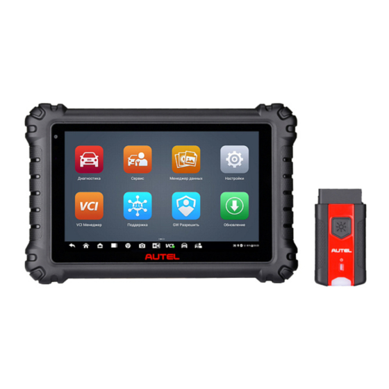
General Introduction The MaxiCOM MK906 Pro/MaxiCOM MK906 Pro-TS (hereinafter referred to as MK906 Pro/MK906 Pro-TS) is an advanced smart wireless diagnostics device providing specialized automotive diagnostic service for customers. Featuring the powerful SDM660/SDA660 octa-core processor, an 8.0-inch TFT-LED capacitive touchscreen,... - Page 12 ⑤ Microphone ⑥ TPMS Service Symbol — indicates the position of the embedded TPMS antenna (for MK906 Pro-TS only) The power LED displays different colors in response to the following scenarios: Green: Illuminates green when the tablet is charging and the battery level is above 90%. Yellow: Illuminates yellow when the tablet is charging and the battery level is below 90%.
-
Page 13: Power Sources
⑤ Headset Jack (3-band 3.5 mm) ⑥ Power/Lock Button — press and hold to turn on/off the tablet, or tap to lock the screen Figure 2-4 MaxiCOM Tablet, Bottom View ① TF Card Slot Power Sources The tablet can receive power from any of the following sources: ... -
Page 14: Technical Specifications
Technical Specifications Table 2-1 Technical Specifications Item Description Operating System Android 10 Octa-core processor (2.2 GHz Qual high- Processor performance Kryo cores + 1.8 GHz Qual low- power Kryo cores) Memory 4 GB RAM & 128 GB on-board memory 8.0-inch TFT-LED capacitive touch screen with Display 1920 x 1200 P resolution ... - Page 15 Item Description ISO 9142-2, ISO 14230-2, ISO 15765-4, K-Line, L-Line, Flashing Code, SAE-J1850 VPW, SAE- J1850 PWM, CAN ISO 11898, High speed, Middle Supported Automotive speed, Low speed and Single wire CAN, GM Protocols UART, UART Echo Byte Protocol, Honda Diag-H Protocol, TP 2.0, TP 1.6, SAE J1939, SAE J1708, Fault-Tolerant CAN...
-
Page 16: Vci - Vehicle Communication Interface
VCI — Vehicle Communication Interface The wireless diagnostic interface MaxiVCI V200 is a small vehicle communication interface (VCI) used to connect to a vehicle’s DLC and connect wirelessly with the tablet for vehicle data transmission. Function Description Figure 2-5 MaxiVCI V200 Views ①... -
Page 17: Technical Specifications
Table 2-3 Connection LED Description Color Description Solid green: The VCI is connected via USB cable. Green Flashing green: The VCI is communicating via Connection USB cable. Solid blue: The VCI is connected via Bluetooth. Blue Flashing blue: The VCI is communicating via Bluetooth. -
Page 18: Accessory Kit
Accessory Kit OBDI Adapters (Optional) The optional OBDI adapters are for Non-OBDII vehicles. The adapter used depends on the type of vehicle being tested. The most common adapters are shown below. Table 2-5 Optional OBDI Adapters Benz-14 PSA-2 Chrysler-16 Mazda-17 Volkswagen/ BMW-20 Audi-2+2... -
Page 19: Other Accessories
Other Accessories Table 2-6 Other Accessories Type-C USB Cable Connects the tablet to the VCI. AC/DC External Power Adapter Connects the tablet to the external DC power port for power supply. Auxiliary Power Outlet Adapter Provides power to the tablet through the vehicle’s auxiliary power outlet. -
Page 20: Getting Started
Getting Started Make sure the tablet has sufficient battery level or is connected to the DC power supply (see Power Sources on page 5). NOTE The images and illustrations depicted in this manual may differ from the actual ones. Powering Up Press the Power/Lock button on the top of the tablet to switch on the unit. -
Page 21: Application Buttons
① Application Buttons ② Locator and Navigation Buttons ③ Status Icons NOTE The screen is locked by default when you first turn on the tablet. It is recommended to lock the screen to protect the information in the system and reduce the power consumption. - Page 22 Checks for the latest update available for the Update MaxiCOM system, and performs updating for details procedures. See Update Launches the Support platform which synchronizes Autel’s on-line service base station Support with the MaxiCOM tablet. See Support details Configures your unit to receive remote support Remote Desktop using the TeamViewer application program.
-
Page 23: Locator And Navigation Buttons
Button Name Description Allows you to submit feedback related to this User Feedback for details product. See User Feedback Provides a quick search for supported functions MaxiViewer for details and/or vehicles. See MaxiViewer Configures the unit to operate as a video scope device by connecting to an imager head cable for MaxiVideo close vehicle inspections. - Page 24 Button Name Description Opens the camera with short press; takes and saves screenshot image with long press. The saved files are Camera auto-stored in the Data Manager application for later reviews. See Data Manager for details. Display & Allows you to adjust the brightness of the screen and the Sound volume of the audio output.
-
Page 25: System Status Icons
System Status Icons By tapping on the bottom right corner, a Shortcuts Panel will be displayed, on which you are allowed to set various system settings of the tablet. Operations of each button on the panel are described in the table below. NOTE The shortcuts buttons will be highlighted when enabled and dimmed when disabled. -
Page 26: Reboot System
Reboot System In case of a system crash, press and hold the Power/Lock button to power off the tablet and restart it. To reboot the tablet Press and hold the Power/Lock button. Tap Restart. Tap OK. The tablet will turn off and restart. -
Page 27: Diagnostics
Diagnostics By establishing a data link to the electronic control systems of the vehicle being serviced through the VCI, the Diagnostics application allows you to retrieve diagnostics information, view live data parameters, and perform active tests. The Diagnostics application can access the electronic control module (ECM) for various vehicle control systems, such as engine, transmission, antilock brake system (ABS), airbag system (SRS) and more. -
Page 28: Vci Connection
NOTE If the vehicle’s DLC is not located under the dashboard. Refer to the user manual of the vehicle for additional connection information. 4.1.1.2 Non-OBDII Vehicle Connection This type of connection requires both the VCI and a required OBDI adapter for the specific vehicle being serviced. -
Page 29: No Communication Message
To pair up the tablet with the MaxiVCI V200 via Bluetooth Power up the tablet. Select the VCI Manager application from the MaxiCOM Job Menu. Select VCI BT from the connection mode list. Tap the Bluetooth toggle to turn it ON. -
Page 30: Getting Started
Try standing closer to the VCI to obtain more stable signals, and faster communication speed. In case of wired connection, check the cable connection between the tablet and the VCI. Check if the Connection LED on the VCI is illuminated for Bluetooth or USB. ... - Page 31 Figure 4-1 Vehicle Menu Screen ① Top Toolbar Buttons ② Manufacturer Icons Top toolbar Buttons The operations of the Toolbar buttons at the top of the screen are listed and described in the table below. Table 4-1 Top Toolbar Buttons Button Name Description...
-
Page 32: Vehicle Identification
Button Name Description America Displays the USA vehicle menu. Europe Displays the European vehicle menu. Asia Displays the Asian vehicle menu. China Displays the Chinese vehicle menu. Opens the virtual keyboard, allowing you to manually Search enter the specific vehicle make required. Cancel Exits the search screen, or cancels an operation. - Page 33 To perform an Auto VIN Scan Tap the Diagnostics application from the MaxiCOM Job Menu. The Vehicle Menu displays. Tap the VID button on the top toolbar. Tap Auto Detect. The tester starts VIN scanning on the vehicle’s ECU. Confirm the vehicle information and the system will guide you to the Vehicle Diagnostics screen directly.
-
Page 34: Manual Vin Input
Manual VIN Input For some vehicles that do not support the Auto VIN Scan function, the MaxiCOM diagnostics system allows you to enter the vehicle VIN manually. To perform Manual VIN Input Tap the Diagnostics application from the MaxiCOM Job Menu. The Vehicle Menu displays. -
Page 35: Manual Vehicle Selection
screen will display on the tablet. If all the vehicle information is correct, tap the icon in the middle of the screen to confirm the VIN of the vehicle being tested, tap OK to continue. Figure 4-5 Scan VIN Code If the VIN/License number cannot be scanned, please manually enter the VIN/License number. -
Page 36: Navigation
Navigation This section describes how to navigate the Diagnostics interface and select test options. Diagnostics Screen Layout The diagnostic screens typically include five sections. Figure 4-6 Diagnostics Screen ① Diagnostics Toolbar ② Current Directory Path ③ Status Information Bar ④ Main Section ⑤... - Page 37 Table 4-2 Diagnostics Toolbar Buttons Button Name Description Home Returns to the MaxiCOM Job Menu. Exits the diagnostics session of the currently Vehicle identified vehicle, and returns to the vehicle menu Swap screen to select another vehicle for testing. Opens the Settings screen. See Settings Settings details.
- Page 38 To print data in Diagnostics Tap the Diagnostics application from the MaxiCOM Job Menu. The Print button on the diagnostics toolbar is available throughout the whole Diagnostics operations. Tap Print whenever you want to make a printing. A drop-down menu displays. Print this page —...
-
Page 39: Making Selections
Function Buttons The displayed Function Buttons at this section of the screen varies depending on the stage of operations. They can be used to navigate, save or clear the diagnostic data, exit scanning as well as make other function controls. The functions of these buttons will be introduced respectively in the following sections of the corresponding test operations. -
Page 40: Diagnosis
The Vehicle Diagnostics screen (Figure 4-2 Vehicle Diagnostics Screen) has 2 main sections: Diagnosis — a comprehensive section which includes all available functions: reading, clearing, saving, and printing diagnostic information, as well as performing active tests and special functions Service — a separate section designed to perform vehicle scheduled service and maintenance, such as to reset the service lights and perform calibration for various systems After a section is selected and the tablet establishes communication with the vehicle via... - Page 41 Navigation Bar List Tab — displays the scanned data in list format. Progress Bar — indicates the test progress. Main Section List Tab Column 1 — displays system numbers. Column 2 — displays scanned systems. Column 3 —...
-
Page 42: Control Unit
Name Description Suspends scanning and changes to show the Continue Pause button. Enter System Enters the ECU system. Returns to the previous screen or exit Auto Scan. Control Unit This option allows you to manually locate a required control system for testing through a series of choices. -
Page 43: Ecu Information
values for certain components after making repairs. Depending on the vehicle, this selection may sometimes appear as Control unit adaptations, Special function, Variant coding, Configuration, etc. NOTE With the diagnostics toolbar on top of the screen throughout the whole diagnostics procedures, you are allowed to make various controls of the diagnostics information at any time, such as printing, and saving the displayed data, getting help information, or performing data logging, etc. -
Page 44: Trouble Codes
③ Function Button — in this case, only an ESC button is available. Tap it to exit after viewing. Trouble Codes Read Codes This function retrieves and displays the DTCs from the vehicle’s control system. The Read Codes screen varies for each vehicle being tested. On some vehicles, freeze frame data can also be retrieved for viewing. - Page 45 Table 4-4 Function Buttons in Trouble Codes Name Description DTC Guide Checks the related help information. Displays when freeze frame data is available for viewing; Tap the icon to display data screen. The Freeze Frame Freeze Frame interface is similar to that of the Read Codes interface and share similar operations.
-
Page 46: Live Data
successful. Live Data When this function is selected, the screen shows the data list for the selected module. The items available for any control module vary from one vehicle to another. The parameters display in the order that they are transmitted by the ECM, so expect variation among vehicles. - Page 47 Display Mode There are 4 types of display modes available for data viewing, allowing you to view various types of parameters in the most suitable way. Tap the drop-down button on the right side of a parameter to open a submenu. A total of 7 buttons will be displayed: The 4 buttons to the left represent different data display modes, plus one Information button, active when additional information is available, and one Unit Change button, for switching the unit of displayed data, and one Trigger button,...
- Page 48 Figure 4-13 Waveform Graph Mode Screen Settings (SetY) — sets the minimum and maximum value of the Y axis. Edit — edits the waveform color and the line thickness. Scale — changes the scale values, which are displayed below the ...
- Page 49 Repeat step 4-7 to edit the waveform for each parameter item. Tap Done to save the settings and exit, or tap Cancel to exit without saving. Digital Gauge Mode — displays the parameters in form of a digital gauge graph. ...
- Page 50 To set a trigger Tap the drop-down button on the right side of a parameter name to open a submenu. Tap the Trigger button on the right side of the submenu to open the trigger settings dialog box. Tap the MIN button on the right side, and enter the required minimum value. Tap the MAX button on the right side, and enter the required maximum value.
- Page 51 Figure 4-15 Setting Mode in Live Data To set live data record duration Tap Setting button at the bottom of the Live Data screen. Tap the > button to the right of Recording time after trigger bar and select a time length.
-
Page 52: Active Test
Review — review the recorded data. Tap the Review button to display a recording list, and select one item to review. NOTE Only the data recorded during the current operation can be reviewed on the Live Data screen. All the historical recorded data can be reviewed in "Review Data" in the Data Manager application. -
Page 53: Special Functions
Figure 4-16 Active Test Screen The function buttons at the lower-right corner of the Active Test screen manipulate the test signals. The operational instructions are displayed on the main section of the test screen. Simply follow the on-screen instructions and make appropriate selections to complete the tests. -
Page 54: Service
Figure 4-17 Adaptation Operation Screen Read the information carefully and check the vehicle condition accordingly, when you are sure that the vehicle is ready to perform the adaptation, simply follow the instruction provided to make appropriate selections. When the operation is done, an execution status message such as Completed, Finished or Successful, displays. -
Page 55: Function Descriptions
Function Descriptions This section describes the main functions for vehicle service: Oil Reset Service This function allows you to perform reset for the Engine Oil Life system, which calculates an optimal oil life change interval depending on the vehicle driving conditions and climate. The Oil Life Reminder must be reset every time the oil is changed, so the system can calculate when the next oil change is required. -
Page 56: General Procedure
monitor status prior to emissions certification testing, verify repairs, and perform a number of other services that are emissions-related. The OBD direct access option is also used for testing OBDII/EOBD compliant vehicles that are not included in the Diagnostics database. Functions of the diagnostics toolbar buttons at the top of the screen are the same as those available for specific vehicle diagnostics. -
Page 57: Function Descriptions
I/M readiness Live data O2 sensor monitor On-Board monitor Component test Vehicle information Vehicle status NOTE Some functions are supported only on certain vehicle makes. Function Descriptions This section describes the various functions of each diagnostic option: DTC &... - Page 58 Pending Codes These are codes whose setting conditions were met during the last drive cycle, but need to be met on two or more consecutive drive cycles before the DTC actually sets. The intended use of this service is to assist the service technician after a vehicle repair and after clearing diagnostic information, by reporting test results after a driving cycle.
-
Page 59: Exiting Diagnostics
O2 Sensor Monitor This option allows retrieval and viewing of O2 sensor monitor test results for the most recently performed tests from the vehicle’s on-board computer. The O2 Sensor Monitor test function is not supported by vehicles which communicate using a controller area network (CAN). For O2 Sensor Monitor tests results of CAN- equipped vehicles, refer to On-Board Monitor. - Page 60 From the Vehicle Menu screen, tap the Home button on the top toolbar; or tap the Back button on the navigation bar at the bottom of the screen. Or Tap the Home button on the diagnostics toolbar to exit the application directly and go back to the MaxiCOM Job Menu.
-
Page 61: Tpms
TPMS The TPMS application is used to check the TPMS sensor conditions, program the MX- Sensor, perform the TPMS Relearn procedure and basic TPMS diagnostic functions. NOTE The TPMS service operation is available for MK906 Pro-TS only. Getting Started Tap TPMS from the MaxiCOM Job Menu, the Vehicle Menu displays. Select the specific vehicle to perform TPMS service. -
Page 62: Vehicle Selection
Auto Detect Properly connect the tablet and vehicle first (refer to Establishing Vehicle Communication for details), then tap the TPMS application button on the MaxiCOM MK906 Pro-TS Home Menu to access the Vehicle Menu. To perform Auto detect in TPMS Tap the TPMS application button from the MaxiCOM Home Menu. - Page 63 Figure 5-2 MaxiCOM Home Menu Tap the VID button on the top toolbar to open the dropdown list. Figure 5-3 VID Screen in TPMS Select Auto Detect. Once the test vehicle is identified, the screen will display the vehicle VIN. Tap OK at the bottom right to confirm the vehicle VIN. If the VIN does not match with the test vehicle’s VIN, enter VIN manually or tap Read to acquire VIN again.
- Page 64 Figure 5-4 Vehicle Information in TPMS Then the TPMS Service Menu will display. See Figure 5-14 TPMS Service Screen. 5.1.1.2 Manual Input For vehicles not supporting the Auto detect function, you may manually enter the vehicle VIN. To perform Manual input Tap the TPMS application button from the MaxiCOM Home Menu (Figure 5-2).
- Page 65 NOTE Before acquiring the vehicle VIN, make sure the tablet is connected to the network. After confirming vehicle information, tap OK to enter the TPMS Service Menu. Figure 5-14 TPMS Service Screen. 5.1.1.3 Scan VIN/License Tap Scan VIN/License (Figure 5-3) in the dropdown list, the camera will be opened. On the right side of the screen, from top to bottom, three options are available: Scan Bar Code, Scan VIN, and Scan License.
- Page 66 To perform Automatic selection Tap the TPMS application button from the MaxiCOM Home Menu (Figure 5-2). The Vehicle Menu displays. Select a vehicle brand on the Vehicle Manufacturer Selection screen. Figure 5-7 Vehicle Brand Selection Tap Automatic Selection in the diagnostic type selection screen. Figure 5-8 Selection Screen in TPMS Tap Read to acquire VIN or manually enter VIN.
- Page 67 Figure 5-9 Automatic Selection in TPMS After that, follow the screen to confirm vehicle information and enter TPMS Service Menu. See Figure 5-14 TPMS Service Screen. 5.1.1.5 Manual Selection You can also tap Manual Selection on the Select diagnostics type screen to select vehicle mode and year step by step.
- Page 68 Figure 5-11 Vehicle Year Selection The following screen may display for vehicles using Indirect TPMS. Figure 5-12 Indirect TPMS Selection Screen For indirect TPMS vehicle, only the Relearn Procedure is supported. Tap the vehicle year information button, in the case of the above screen — 2008/08-2019/12 (indirect), to display the Relearn Procedure.
-
Page 69: Tpms Service Screen Layout
Figure 5-13 Relearn Procedure for Indirect TPMS For vehicles using Direct TPMS, select the correct vehicle. The TPMS service menu will display next. Figure 5-14 TPMS Service Screen TPMS Service Screen Layout The screens in TPMS service application typically include four sections. - Page 70 Figure 5-15 Sample TPMS Service Screen Layout ① Top Toolbar Buttons ② Navigation Tab ③ Main Section ④ Function Buttons Top Toolbar Buttons The top toolbar contains a number of buttons that allow you to print or save the displayed data and make other controls.
-
Page 71: Check Operations
Main Section The main section of the screen varies depending on the stage of operations. The main section can show the TPMS sensor conditions, such as sensor ID, pressure, temperature and battery status, and the specific relearn procedures. Function Buttons The displayed function buttons at this section of the screen varies depending on the stage of operations. - Page 72 NOTE You can tap the dropdown button on the table header to choose a unit of the sensor ID, tire pressure, and tire temperature according to your preference. To check TPMS sensor Tap the Check tab. Tap the desired wheel position on the vehicle thumbnail. Hold the tablet with its top right corner (with the TPMS service symbol) close to the tire sidewall near the valve stem, and then press the Trigger button.
-
Page 73: Diagnostics Operations
Diagnostics Operations The Diagnostics function is used to check the status of the TPMS system. This function requires connection with the test vehicle. Refer to Establishing Vehicle Communication for details. Tap the Diagnostics tab, the tablet will automatically communicate with the vehicle. Figure 5-17 Diagnostics Communication Screen Figure 5-18 Diagnostics Screen Sample 1 Sensor IDs Retrieved by Activation... -
Page 74: Detail
If the sensor ID retrieved from sensor activation is the same as the ID saved in the ECU, the trigger mark ( ) and OBD mark ( ) beside the IDs will display green. If the IDs are different, the marks will become red ( ). -
Page 75: Retry Diagnosis
If no DTCs are present in the TPMS ECU, a green “No DTC” message will display in the DTC column. Figure 5-21 No DTC Screen Retry Diagnosis Tap Retry Diagnosis to establish communication with the ECU again and to retrieve sensor IDs and DTCs present in the ECU. -
Page 76: Ecu Information
Check box before the parameters you want to see, the Show selected icon on the bottom of the screen will be available and turn blue. Tap Show selected and the selected parameters will be displayed in a separate screen. For more details, please refer to Live Data. -
Page 77: Copy By Activation
NOTE Programming function will only work with Autel’s MX-Sensor. Currently, there are two models available: Clamp-in Sensor and Snap-in Sensor, both with two types, one in orange color with 433 MHz frequency, and one in dark gray color with 315 MHz frequency. -
Page 78: Copy By Obd
Figure 5-26 Copy by Activation Function Screen The programed sensor ID will appear on Column 2. Copy by OBD This function allows users to copy the OBD retrieved sensor ID into MX-Sensor after performing Read IDs combined in the Diagnostics function. Figure 5-27 Copy by OBD Function Main Screen ... -
Page 79: Copy By Input
NOTE If you have successfully performed both Check and Diagnostics functions, you can select either Copy by Activation or Copy by OBD to program the retrieved sensor ID to the MX-Sensor. Copy by Input This function allows you to manually enter sensor IDs. You can enter a random ID or the original sensor ID. -
Page 80: Relearn Operations
NOTE It is necessary to perform Relearn procedure after installing the new MX-Sensor programmed by the way of Auto Create. Relearn Operations This function allows quick access to the vehicle’s ECU, performing TPMS diagnostics, reading IDs from vehicle, writing IDs to the vehicle and reading/clearing codes of tire pressure monitoring system. -
Page 81: Automatic Relearn
Copy Relearn is to clone the sensor ID and tire location. Before performing Copy Relearn, it is necessary to obtain the sensor ID and tire location that need to be cloned, then use Autel tools to clone and program the sensor ID, and install the sensor to the corresponding tire to complete Copy Relearn. -
Page 82: Retrofit Operations
Tap the TPMS retrofit tab. Follow the instructions displayed on the screen, which will guide you to choose the procedure, including the Back-up, Retrofit, Restore, Program Autel ECU, Autel ECU Relearn and Service Function buttons. After the retrofit function is finished, tap on the other tabs to perform optional... -
Page 83: Tpms By Oem Part No
TPMS by OEM Part NO. If the sensor’s OEM part number is known, this function is an efficient method to activate and program MX-Sensors. Application Scenarios This method is ideal for the following two cases: In the Workshop If the mounted sensor is faulty and the part number is known to the technician, the technician can use this method to check the original sensor, and then write the information that was retrieved into a new MX-Sensor via Programming. - Page 84 Figure 5-32 OEM Part NO. Search Screen When a specific OEM Part NO. is selected, the screen will display as below. Figure 5-33 OEM Part NO. Service Menu NOTE Only sensor Check and Programming functions are available with the OEM Part NO. function.
- Page 85 Figure 5-34 Check Screen via OEM Part NO. Programming The programming function is used to program the sensor data to the MX-Sensor and replace the faulty sensor (poor battery life or malfunction). There are three options available when programming MX-Sensor using the OEM Part NO.
- Page 86 The Product Serial Number (PSN) Code, which is printed on the MX-Sensor, acts as reference to identify the corresponding sensor ID. This can be especially useful when programming multiple MX-Sensors. Support Support will display the correct vehicle types for the selected OEM part number. To conduct additional procedures such as Diagnostics and Relearn, select the correct test vehicle model and then tap Enter Vehicle at the bottom left of the screen.
-
Page 87: Service
Service The Service application is designed to provide quick access to the vehicle systems for various scheduled service and maintenance tasks. The typical service operation screen is a series of menu driven executive commands. Follow on-screen instructions to select appropriate execution options, enter correct values or data, and perform necessary actions. -
Page 88: Oil Reset
Only perform maintenance work when the vehicle is stationary and on level ground. Ensure that the EPB control system is reactivated after the maintenance work has been completed. NOTE Autel accepts no responsibility for any accident or injury arising from the maintenance of the Electric Parking Brake system. -
Page 89: Tire Pressure Monitoring System (Tpms)
Tire Pressure Monitoring System (TPMS) This function allows you to quickly look up the tire sensor IDs from the vehicle's ECU, as well as to perform TPMS replacement and reset procedures after tire sensors are replaced. Battery Management System (BMS) The Battery Management System (BMS) allows the tool to evaluate the battery charge state, monitor the close-circuit current, register the battery replacement, activate the rest state of the vehicle, and charge the battery via the diagnostic socket. -
Page 90: Steering Angle Sensor (Sas)
Accident repairs where damage to the steering angle sensor or assembly, or any part of the steering system may have occurred NOTE Autel accepts no responsibility for any accident or injury arising from servicing the SAS system. When interpreting DTCs retrieved from the vehicle, always follow the manufacturer's recommendation for repair. -
Page 91: Oem Authorization
OEM Authorization The OEM Authorization application allows to unlock the gateway ECU (CGW) for some vehicles to perform advanced diagnostics tests. NOTE Make sure the tablet is connected to the Internet before launching the OEM Authorization application. To unlock the gateway ECU (CGW) Connect the MaxiCOM Diagnostics Platform to the vehicle through the VCI. - Page 92 Figure 7-2 Purchase Screen Exit the Diagnostics application. Tap OEM Authorization on the MaxiCOM Job Menu. On the OEM Authorization screen, tap Renew. The Unlocking Information screen appears, on which you can view the remaining service sessions. Figure 7-3 Unlocking Information Screen...
-
Page 93: Battery Test
Battery Test The MaxiBAS BT506 is a battery and electrical system analysis tool that uses Adaptive Conductance, an advanced battery analysis method to produce a more accurate examination of the battery’s cold cranking ability and reserve capacity, which is vital to determining a battery’s true health. -
Page 94: Power Sources
Table 8-1 LED Description Color Description Flashing Green The tester is communicating via USB cable. Status Flashing Blue The tester is communicating via Bluetooth. Battery clamps are connected to the wrong battery Flashing Red terminals. The tester is powered on and the battery is sufficiently Solid Green charged. -
Page 95: Technical Specifications
Technical Specifications Table 8-2 Technical specifications Item Description USB 2.0, Type C Connectivity Bluetooth 4.2 Input Voltage 5 V DC Working Current < 150 mA at 12 V DC Internal Battery 3.7 V/800 mAh Lithium-ion Polymer battery CCA Range 100 to 2000 A Voltage Range 6 to 36 V... -
Page 96: Connecting To A Battery
When pairing is successful, the connection status reads “Connected.” Once paired, the VCI button on the upper right corner of the screen will display a green badge and the Connection LED on the MaxiBAS BT506 illuminates blue. This signifies that the tablet is connected to the MaxiBAS BT506, and is ready to for use. -
Page 97: In-Vehicle Test
In-vehicle Test In-vehicle Test is used for testing batteries that are installed in a vehicle. An in-vehicle test includes battery test, starter test, and generator test. These tests help determine the health status of the battery, the starter, and the generator, respectively. IMPORTANT Before using the diagnostic functions, download the desired vehicle software on the Update screen. - Page 98 Figure 8-4 OBD Connect Screen Confirm the vehicle information. The Vehicle information screen automatically displays when vehicle communication is established. A Battery location button will pop up from the bottom of the screen. Figure 8-5 Vehicle Information Screen Table 8-3 Upper Toolbar Buttons Button Name Description...
- Page 99 Tap Next and access the Battery tab. Perform required operations before the battery test based on the on-screen instructions. And tap the Start Testing button. Figure 8-6 Battery Screen Wait for the battery test to complete and view the test results. Figure 8-7 Battery Result Screen Possible in-vehicle test results are as follows: ...
-
Page 100: Starter Test
Starter Test To perform the starter test Tap Continue. Perform required operations before the battery test based on the on-screen instructions. And tap the Start Testing button. Turn the vehicle ignition to ON when the following screen displays. Wait for the test to complete and view the test results. Figure 8-8 Starter Screen Sample 1 Figure 8-9 Starter Screen Sample 2... - Page 101 Figure 8-10 Starter Test Result Screen Possible starter test results are as follows: Cranking Normal Current Too Low Voltage Too Low Not Started...
-
Page 102: Generator Test
Generator Test To perform the generator test Tap Continue. Perform required operations based on the on-screen instructions. Figure 8-11 Generator Test Screen Tap Continue and view the test results. Figure 8-12 Generator Test Result Screen Possible generator test results are as follows: ... -
Page 103: Out-Vehicle Test
Out-vehicle Test Out-vehicle test is used to test the condition of batteries that are not connected to a vehicle. This function aims to check the health status of the battery only. The battery types and standards able to be tested are as follows. Types: FLOODED, AGM, AGM SPIRAL, EFB, and GEL Standards: CCA, SAE, CA, EN, IEC, DIN, JIS, and MCA Battery Test... - Page 104 Figure 8-14 Sample Out-vehicle Test Result Screen Possible out-vehicle test results are as follows: Good Battery Good & Recharge Charge & Retest Replace Battery Bad Cell...
-
Page 105: Data Manager
Data Manager The Data Manager application allows you to store, print, and review the saved files, manage the workshop information, customer information records, and keep vehicle history records. Tapping the Data Manager application opens the file system menu. There are nine main functions available. -
Page 106: Vehicle History
Button Name Description Review Data Review the recorded data. Uninstall Apps Uninstall applications. Review the communication data and ECU information of the vehicle. The saved data Data Logging can be reported and sent to the technical center via the internet. Vehicle History This function stores records of vehicle history, including vehicle information and the retrieved DTCs from previous diagnostics sessions. -
Page 107: Historical Test Record
operations. Or, Select a vehicle thumbnail. A historical test record screen displays. Review the recorded information of the vehicle, and tap the Diagnostics button on the upper-right corner to continue diagnostics. Historical Test Record The historical test record is a detailed data form of the tested vehicle, which includes general vehicle information, service record, customer information, and the diagnostic trouble codes retrieved from the previous test sessions. -
Page 108: Workshop Information
with the vehicle record. See Customer for more information. Tap Done to save the updated record, or tap Cancel to exit without saving. Workshop Information The Workshop Information screen allows you to enter, edit, and save the detailed workshop information, such as shop name, address, phone number, and other remarks, which, when printing vehicle diagnostics reports and other associated test file, will display as the header of the printed documents. -
Page 109: Customer
Customer The Customer function allows you to create and edit customer accounts. It helps you to save and organize all customer information accounts that are correlated with the associated vehicle history records. To create a customer account Tap the Data Manager application on the MaxiCOM Job Menu. Tap Customer. -
Page 110: Report
Report The Report section stores diagnostics reports. You can view local reports or share the report to Autel cloud after entering the report database and selecting a specific report. Image The Image section is a PNG database containing all captured screenshots. -
Page 111: Pdf
To edit/delete image(s) Tap Data Manager from the MaxiCOM Job Menu. Tap Image to access the PNG database. Tap Edit on the top right corner of the screen. The editing screen displays. Select the image(s) you want to edit. Tap Delete to delete the selected images or delete all images. -
Page 112: Uninstall Apps
Uninstall Apps This section allows you to manage the software applications installed on the MaxiCOM Diagnostics System. Selecting this section opens a managing screen, on which you can check all the available vehicle diagnostic applications. Select the vehicle software you want to delete by tapping on the car brand icon, the selected item will display a blue check mark at the upper right corner. -
Page 113: Settings
Settings Access the Settings menu to adjust default setting and view information about the MaxiCOM system. The following options are available for the MaxiCOM system settings: Units Language Printing Settings Report Settings Auto Update TPMS Market (for MK906 Pro-TS) ... -
Page 114: Language
Download Maxi PC Suite from www.autel.com > Support > Downloads > Autel Update Tools, and install to your PC. Double click the setup.exe file. Select the installation language and the wizard will load momentarily. Follow the instructions on the screen and click Next to continue. -
Page 115: Report Settings
This section describes how to receive file from the MaxiCOM tablet and print the file using the PC. NOTE Make sure the tablet is connected to the PC network, either via Wi-Fi or LAN, before printing. Make sure the PC installed with the Printing Services program is connected to a printer. -
Page 116: Tps Prog. Setting
TPS Prog. Setting This option allows you to set the TPS program pressure limit. The available options are Prog. Pressure ≤ 69Kpa/10PSI and No Prog. Pressure Limit. A check mark will display to the right of the selected item. Vehicle List This option allows you to sort the vehicles either by alphabetic order or by frequency of use. -
Page 117: Vci Manager
VCI Manager This application allows you to pair up the tablet with the VCI, check the communication status, and update the firmware of the VCI and battery tester BT506. Figure 11-1 VCI Manager Screen ① Connection mode — there are four connection modes available for selection. The connection state is displayed alongside. - Page 118 To update the BT506 Power on the tablet and the BT506. Connect the BT506 to the tablet via Bluetooth or USB. Tap VCI Manager on the MaxiCOM Job Menu of the tablet. Tap BAS Update from the connection mode list. The current version and the latest version of the BT506 will appear.
-
Page 119: Update
Update The Update application allows you to download the latest released software. The updates can improve the MaxiCOM applications’ capabilities, typically by adding new tests, new models, or enhanced applications to the database. The tablet automatically searches for available updates for all of the MaxiCOM software when it is connected to the internet. - Page 120 ③ Main Section Left Column — displays vehicle logos. Middle Column — displays a brief introduction about the new changes to the software operation or capabilities. Tap the button to open an information screen to view more details, and tap the dim area around to close the window. Right Column —...
-
Page 121: Support
Visit the website: http://pro.autel.com. If you have an Autel account, sign in with your account ID and password. If you are a new member to Autel, click the Register button to create your Autel ID. Enter the required personal information in the input fields. -
Page 122: My Account
The Service Info tab displays a detailed record list of the device’s service history information. Every time the device has been sent back to Autel for repair, the device’s serial number and the detailed repair information, including Service date, Type of faults, and Repair content, will be recorded and updated to the associated online product account, which will be synchronized to the Service Info tab. -
Page 123: Training
The Training screen provides quick links to Autel’s online video accounts. Select a video channel by the language to see all the available online tutorial videos from Autel for various technical supports, such as product usage techniques and vehicle diagnostics practice, etc., may be available for your interests. -
Page 124: Faq
Autel’s online member account, and shopping and payment procedures. Account — displays questions and answers about the use of Autel’s online user account. Shopping & Payment — displays questions and answers about online product... -
Page 125: Remote Desktop
The Remote Desktop application launches the TeamViewer QuickSupport program, which is a simple, fast and secure remote control interface. You can use the application to receive ad-hoc remote support from Autel’s support technicians by allowing them to control your MaxiCOM tablet on their PC via the TeamViewer software. - Page 126 you a remote control request. A popup dialog box displays to ask for your confirmation to allow remote control on your device. Tap Allow to accept, or tap Deny to reject. Refer to the associated TeamViewer documents for additional information.
-
Page 127: User Feedback
To help us resolve the issue more efficiently, we recommend you complete the form with as much details as possible. Tap Submit to send the completed form to Autel's online service center. The submitted feedback will be carefully read and handled by our service personnel. -
Page 128: Maxiviewer
MaxiViewer The MaxiViewer application allows you to search the functions supported by our tools and the version information. There are two ways of searching, either by searching the product and the vehicle or searching the functions. To search by product and vehicle Tap MaxiViewer on the MaxiCOM Job Menu. - Page 129 To search by functions Tap MaxiViewer on the MaxiCOM Job Menu. The Function Viewer screen displays. Select a product from the Product Type drop-down list. Tap the Search icon. Enter the desired function in the search box. The screen will display all vehicles that support this function, along with information such as the vehicles' year, system, capacity, type, function, sub-function, and version.
-
Page 130: Maxivideo
MaxiVideo The MaxiVideo application configures the MaxiCOM Diagnostics Device to operate as a digital video scope by simply connecting the tablet to a MaxiVideo Camera. This function allows you to examine difficult-to-reach areas normally hidden from sight, with the ability to record digital still images and videos, which offers you an economical solution to inspect machinery, facilities, and infrastructure in a safe and quick way. -
Page 131: Maxivideo Camera
MaxiVideo Camera Figure 17-1 MaxiVideo Camera ① Removable Imager Head Cable — connects to the tool when performing MaxiVideo cameras for image and video viewing. ② Handgrip — ergonomically designed handle for comfortable grips and agile operation. ③ USB Cable — connects the MaxiVideo Camera to the MaxiCOM tablet. Imager Head Accessories Figure 17-2 8.5 mm Imager Head Accessories ①... -
Page 132: Accessory Assembly
Figure 17-3 5.5 mm Imager Head Accessories ① Mirror — helps to look around corners and see the unreachable areas. ② Magnet — picks up small metal objects, such as dropped rings or screws. Accessory Assembly 8.5 mm Imager Head The three accessories, including the Magnet, Hook, and Mirror, can be attached to the Imager Head in the same manner described below: Hold the accessory and the imager head. -
Page 133: Technical Specifications
5.5 mm Imager Head The two accessories, the Magnet and Mirror, can be attached to the Imager Head in the same manner described below: Hold the accessory and the imager head. Screw the thread part of the accessory over the imager head to fix the accessory. Technical Specifications Table 17-1 Technical Specifications Item... -
Page 134: Operations
Item Description 0.3 kg for 8.5 mm diameter imager head Weight 0.2 kg for 5.5 mm diameter imager head Operations Before opening the MaxiVideo application, the imager head cable must be connected to the tablet using the USB cable. Install the correct imager head accessories according to the specific needs. - Page 135 Properly locate the imager head cable to focus the inspection scene for recording. Tap the red ring on the operating screen to start recording. Tap the red circle again to stop recording. The recorded video is automatically saved. Tap the gallery icon at the bottom-right corner to review all recorded videos. Select the corresponding button on the upper-right corner to search or delete a video.
-
Page 136: Quick Link
Quick Link The Quick Link application provides you with convenient access to Autel’s official website and many other well-known sites in automotive service, which offers you abundant information and resources, such as technical help, knowledge base, forums, training, and expertise consultations. -
Page 137: Maintenance And Service
Maintenance and Service To ensure that the MaxiCOM diagnostic tablet and the combined VCI perform at their optimum level, we advise that the product maintenance instructions covered in this section is read and followed. Maintenance Instructions The following shows how to maintain your devices, together with precautions to take. ... -
Page 138: About Battery Usage
Your device may have not been connected to the charger properly. Check the connector. NOTE If your problems persist, please contact Autel’s technical support personnel or your local selling agent. About Battery Usage Your tablet is powered by a built-in Lithium-ion Polymer battery. This means that, unlike other forms of battery technology, you can recharge your battery while some charge remains without reducing your tablet’s autonomy due to the “battery memory effect”... -
Page 139: Service Procedures
Technical Support If you have any question or problem on the operation of the product, please: Call 1-855-288-3587/1-855-AUTELUS (North America). Contact the local distributer or agent. Visit our website http://pro.autel.com or www.autel.com. -
Page 140: Repair Service
Repair Service If it becomes necessary to return your device for repair, please download the repair service form from www.autel.com, and fill in the form. The following information must be included: Contact name Return address Telephone number ... -
Page 141: Compliance Information
Compliance Information FCC Compliance FCC ID: WQ8-MS906PRO2121 (for MK906 Pro) FCC ID: WQ8-MS906TS2121 (for MK906 Pro-TS) This device complies with Part 15 of the FCC rules and Industry Canada’s license- exempt RSSs. Operation is subject to the following two conditions: This device may not cause harmful interference. -
Page 142: Rf Warning Statement
RF WARNING STATEMENT The device has been evaluated to meet general RF exposure requirement. The device can be used in portable exposure condition without restriction. CE Compliance RED Directive 2014/53/EU RoHS Compliance This device is declared to be in compliance with the European RoHS Directive 2011/65/EU. -
Page 143: Warranty
Warranty 12-Month Limited Warranty Autel Intelligent Technology Corp., Ltd. (the Company) warrants to the original retail purchaser of this MaxiCOM Diagnostics Device, that should this product or any part thereof during normal consumer usage and conditions, be proven defective in material...
Need help?
Do you have a question about the MaxiCOM MK906 Pro and is the answer not in the manual?
Questions and answers