Autel MaxiPRO MP808 Manual
Hide thumbs
Also See for MaxiPRO MP808:
- Quick reference manual (2 pages) ,
- User manual (111 pages) ,
- Manual (111 pages)
Table of Contents
Advertisement
Quick Links
Trademarks
®
Autel
,
MaxiSys
®
MaxiCheck
are trademarks of Autel Intelligent Technology Corp., Ltd., registered in
China, the United States and other countries. All other marks are trademarks or
registered trademarks of their respective holders.
Copyright Information
No part of this manual may be reproduced, stored in a retrieval system or transmitted, in
any form or by any means, electronic, mechanical, photocopying, recording, or otherwise
without the prior written permission of Autel.
Disclaimer of Warranties and Limitation of Liabilities
All information, specifications and illustrations in this manual are based on the latest
information available at the time of printing.
Autel reserves the right to make changes at any time without notice. While information of
this manual has been carefully checked for accuracy, no guarantee is given for the
completeness and correctness of the contents, including but not limited to the product
specifications, functions, and illustrations.
Autel will not be liable for any direct, special, incidental, indirect damages or any
economic consequential damages (including the loss of profits).
IMPORTANT
Before operating or maintaining this unit, please read this manual carefully, paying extra
attention to the safety warnings and precautions.
For Services and Support
pro.autel.com
www.autel.com
1-855-288-3587/1-855-AUTELUS (North America)
0086-755-86147779 (China)
Support@autel.com
For technical assistance in all other markets, please contact your local selling agent.
®
®
,
MaxiDAS
,
®
MaxiScan
,
MaxiTPMS
i
®
,
MaxiRecorder
®
,
and
Advertisement
Table of Contents

Related Manuals for Autel MaxiPRO MP808


Summary of Contents for Autel MaxiPRO MP808
- Page 1 All information, specifications and illustrations in this manual are based on the latest information available at the time of printing. Autel reserves the right to make changes at any time without notice. While information of this manual has been carefully checked for accuracy, no guarantee is given for the completeness and correctness of the contents, including but not limited to the product specifications, functions, and illustrations.
- Page 2 Safety Instructions The safety messages herein cover situations Autel is aware of. Autel cannot know, evaluate or advise you as to all of the possible hazards. You must be certain that any condition or service procedure encountered does not jeopardize your personal safety.
- Page 3 SAFETY WARNINGS Always perform automotive testing in a safe environment. Wear safety eye protection that meets ANSI standards. Keep clothing, hair, hands, tools, test equipment, etc. away from all moving or hot engine parts. Operate the vehicle in a well-ventilated work area, for exhaust gases are poisonous. ...
-
Page 4: Table Of Contents
CONTENTS USING THIS MANUAL ....................1 ........................1 ONVENTIONS Hyperlink ........................1 Illustrations ........................1 GENERAL INTRODUCTION ..................2 PRO MP808 T ....................2 ABLET Function Description ....................2 Power Sources ......................3 Technical Specifications ..................... 4 ......................5 THER CCESSORIES Main Cable ........................ - Page 5 Control Unit ....................... 21 ......................30 UNCTIONS Oil Reset Service ...................... 30 Tire Pressure Monitor System (TPMS) Service ............30 Electric Parking Brake (EPB) Service ............... 31 ABS/SRS Services....................31 Steering Angle Sensor (SAS) Service ............... 31 DPF Regeneration Service ..................31 OBDII O ..................
- Page 6 Vehicle Management ....................55 Data Logging ......................55 SETTINGS ........................ 56 ..........................56 ........................56 ANGUAGE ......................57 RINTING ETTINGS Printing via APP ......................57 Printing via PC ......................57 ......................58 EPORT ETTINGS ........................58 ULTITASK ....................... 58 IRMWARE PGRADE .........................
- Page 7 ....................75 CCESSORY SSEMBLY ..................... 77 ECHNICAL PECIFICATIONS ........................77 PERATIONS MAINTENANCE AND SERVICE................79 ................... 79 AINTENANCE NSTRUCTIONS ..................79 ROUBLESHOOTING HECKLIST ....................80 BOUT ATTERY SAGE ....................81 ERVICE ROCEDURES Technical Support ..................... 81 Repair Service ......................82 Other Services ......................
-
Page 8: Using This Manual
Using This Manual This manual contains device usage instructions. Some illustrations shown in this manual may contain modules and optional equipment that are not included in your system. Contact your sales representative for availability of other modules and optional tools or accessories. Conventions The following conventions are used. -
Page 9: General Introduction
General Introduction Based on the Android operating system, MaxiPRO MP808 is featured with an extensive coverage of OE-level diagnostics. Installed with a fast quad-core processor, MP808 offers maximum convenience and efficiency for your diagnosis and analysis. The intuitive user interface makes using the device effortless through a 7-inch LCD touchscreen that displays at 1024 x 600 quality. -
Page 10: Power Sources
C. Red Illuminates red when the tablet is powered on and the battery level is below 15%. Figure 2-2 MaxiPRO MP808, Back View Collapsible Stand — extends from the back to allow hands-free viewing of the tablet. Heat Sink... -
Page 11: Technical Specifications
Internal Battery Pack The tablet can be powered with the internal rechargeable battery, which if fully charged can provide sufficient power for about 4.5 hours of continuous operation. Vehicle Power When the tablet is connected to the test vehicle via the main cable, the tablet automatically receives power from the vehicle. -
Page 12: Other Accessories
Item Description 500 mA (LCD on with default brightness, Wi-Fi Power Consumption on) @3.7 V Operating Temp. 0 to 50 ° C (32 to 122 ° F) Storage Temp. -10 to 60 ° C (14 to 140 ° F) Operating Humidity 5 % to 95 % non-condensing 237.8 mm (9.4”) x 148.6 mm (5.9”) x 35.5 mm Dimensions (W x H x D) -
Page 13: Getting Started
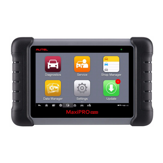
LED light will illuminate green. The system boots up and displays the lock screen. Slide the Lock icon to the left to enter the MaxiPRO Job Menu or slide to the right to unlock. Figure 3-1 Sample MaxiPRO MP808 Job Menu Application Buttons Locator and Navigation Buttons... -
Page 14: Application Buttons
Checks for the latest update available for the Update MaxiPRO system and performs updates. See Update for details. Launches the Support platform which synchronizes Support Autel’s on-line service base station with the MaxiPRO tablet. See Support for details. - Page 15 See Quick Link for details. Provides quick search for the supported functions Function and vehicles of Autel diagnostic tools. See Function Viewer Viewer for details. Configures the unit to operate as a video scope...
-
Page 16: Locator And Navigation Buttons
Locator and Navigation Buttons Operations of the Navigation buttons at the bottom of the screen are described in the table below: Table 3-2 Locator and Navigation Buttons Button Name Description Indicates the location of the screen. Swipe the Locator screen left or right to view the previous or next screen. -
Page 17: Powering Down
NOTE The shortcuts buttons will be highlighted when enabled and dimmed when disabled. Table 3-3 Shortcuts Panel Buttons Button Name Description Calculator Launches calculator when pressed. Clock Launches clock when pressed. Wi-Fi Enables/disables Wi-Fi when pressed. Enables/disables Airplane Mode when Airplane Mode pressed. -
Page 18: Diagnostics
Vehicle Menu Layout When the tablet is properly connected to the vehicle, the platform is ready to start vehicle diagnosis. Tap on the Diagnostics application button on the MaxiPRO MP808 Job Menu to access the Vehicle menu. Figure 4-1 Sample Vehicle Menu... -
Page 19: Vehicle Identification
Table 4-1 Top Toolbar Buttons Button Name Description Home Returns to the MaxiPRO Job Menu. Provides a fast way to identify the test vehicle. VIN Scan Auto VIN Scan for details. Displays all the vehicle makes in the vehicle menu. Displays the stored test vehicle history records. - Page 20 Tap the VIN Scan button on the top toolbar to open the dropdown list. Figure 4-2 Sample Auto VIN Screen Select Auto Detect. Once the test vehicle is identified, the screen will display the vehicle VIN. Tap OK at the bottom right to confirm the vehicle VIN. If the VIN does not match with the test vehicle’s VIN, enter VIN manually or tap Read to acquire VIN again.
-
Page 21: Manual Vin Input
The tool establishes communication with the vehicle and reads the control unit information. Choose Auto Scan to scan all the test vehicles’ available systems or tap Control Unit to access a specific system to diagnose. Figure 4-5 Sample Diagnostic Screen Manual VIN Input For vehicles not supporting the Auto VIN Scan function, you may manually enter the vehicle VIN. -
Page 22: Automatic Selection
Tap Cancel to exit Manual Input. Automatic Selection The Auto VIN Scan can be selected after selecting the test vehicle manufacturer. Figure 4-7 Sample Selection Screen To perform Automatic Selection Tap the Diagnostics application button from the MaxiPRO Job Menu. The Vehicle Menu displays. -
Page 23: Diagnostics Screen Layout
Diagnostics Screen Layout Figure 4-8 Sample Diagnostics Screen The diagnostic screens typically include four sections. Diagnostics Toolbar Status Information Bar Main Section Function Buttons Diagnostics Toolbar The Diagnostics Toolbar contains a number of buttons such as print and save. The table below provides a brief description of the operations of the Diagnostics Toolbar buttons. - Page 24 Button Name Description Tap Take a Screenshot to take a screenshot of the current screen. Tap Save All Data to save a PDF file (use this save option when data displays on multiple screens). Tap Save Report to save the data in a report form.
-
Page 25: Screen Messages
Main Section The Main Section of the screen varies depending on the stage of operations. The Main Section can display vehicle identification selections, the main menu, test data, messages, instructions, and other diagnostic information. Function Buttons The displayed Function Buttons vary depending on the stage of operations. Function Buttons can be used to navigate menus, to save or clear diagnostic data, to exit scanning and to perform a number of other control functions. -
Page 26: Diagnosis
The Vehicle Diagnostics screen has two main options: Figure 4-9 Sample Main Menu Diagnosis — a comprehensive section which includes all available functions: reading, clearing, saving and printing diagnostic information, as well as performing active tests and special functions. Hot Function — a separate section designed to perform vehicle scheduled service and maintenance, such as to reset the service lights and perform calibration for various systems. - Page 27 Figure 4-10 Sample Auto Scan Operation Screen Navigation Bar Main Section Function Buttons Navigation Bar List Tab — displays the scanned data in list format. Progress Bar — indicates the test progress. Main Section Column 1 — displays the sequence numbers. Column 2 —...
-
Page 28: Control Unit
Table 4-3 Function Buttons in Auto Scan Name Description Displays the diagnostic data in the report form. Report Deletes codes. A warning message screen will display to Quick inform you of possible data loss when this function is selected. Confirms the test result. Continues to the system diagnosis after required system is selected by tapping the item in the Main Section. - Page 29 DTC records and other data from the test vehicle’s ECU. Freeze Frame — displays the freeze frame data of the DTCs. Live Data — retrieves and displays live data and parameters from the test vehicle’s ECU. Active Test — provides specific subsystem and component tests. This selection may ...
- Page 30 specifications or descriptions. Function Button — ESC (or Back) button is available; tap it to exit after viewing. Trouble Codes Read Codes This function retrieves and displays the DTCs from the vehicle’s control system. The Read Codes screen varies for each vehicle being tested. On some vehicles, freeze frame data can also be retrieved for viewing.
- Page 31 To erase codes Tap Trouble Codes from the Function Menu, then tap Erase Codes. A warning message displays to advice of data loss if this function is completed. Tap Yes to continue. A confirming screen displays when the operation is successfully done.
- Page 32 Unit Column — displays the unit for the parameters. To change the unit mode, tap the Setting button on the top toolbar and select a required mode. See Unit for more information. Display Mode There are four types of display modes available for data viewing. Select the proper mode for the diagnostic purpose.
- Page 33 To edit the waveform color and line thickness in a data graph Select 1 to 3 parameter items to display in Waveform Graph mode. Tap the Zoom-in Button on the right to display the data graph in full screen. Select a parameter item on the left column.
- Page 34 Setting — tap this button to access setting menu to set the trigger mode, recording duration and threshold values for data recording, and define other control settings. Figure 4-15 Sample Setting Mode in Live Data There are four navigation buttons on top of the Setting mode screen. Selected Button —...
- Page 35 If the threshold limits are successfully set, two horizontal lines will display on each of the data graphs (when Waveform Graph Mode is applied) to indicate the alarm point. The threshold lines are displayed in different colors from the waveform of the parameters. Record Button —...
- Page 36 Selecting Active Test opens a menu of test options that varies by make and model. Selecting a menu option activates the test. Follow on-screen instructions while performing tests. The content and pattern of the on-screen information vary according to the type of test being performed. Some toggle and variable control tests display Active Test Controls at the top of the screen with data stream information below, or vice versa.
-
Page 37: Hot Functions
Figure 4-17 Sample Special Functions Screen Hot Functions The Service section is specially designed to provide you with quick access to the vehicle systems for various scheduled service and maintenance performances. The typical service operation screen is a series of menu driven executive commands. By following the on-screen instructions to select appropriate execution options, enter correct values or data, and perform necessary actions, the system will guide you through the complete performance for various service operations. -
Page 38: Electric Parking Brake (Epb) Service
Electric Parking Brake (EPB) Service This function has a multitude of usages to maintain the electronic braking system safely and effectively. The applications include deactivating and activating the brake control system, assisting with brake fluid control, opening and closing brake pads, and setting brakes after disc or pad replacement, etc. - Page 39 Tap the EOBD button. There are two options to establish communication with the vehicle. Auto Scan — when this option is selected, the diagnostic tool attempts to establish communication using each protocol in order to determine the one from which the vehicle is broadcasting. Protocol —...
-
Page 40: Function Descriptions
Function Descriptions This section describes the various functions of each diagnostic option: DTC & FFD When this function is selected, the screen displays a list of Stored and Pending Codes. A snowflake button will display on the right side of the DTC item when the Freeze Frame data is available for viewing. - Page 41 Freeze Typically, the stored frame is the last DTC that occurred. Certain DTCs that have a greater impact on vehicle emission, have a higher priority. In these cases, the top prioritized DTC is the one for which the freeze frame records are retained. Freeze data includes a “snapshot”...
- Page 42 Component Test This service enables bi-directional control of the ECM so that the diagnostic tool is able to transmit control commands to operate the vehicle systems. This function is useful in determining whether the ECM responds to a command well. Vehicle Information The option displays the vehicle identification number (VIN), the calibration identification, and the calibration verification number (CVN), and other information of the test vehicle.
-
Page 43: Exiting Diagnostics
Exiting Diagnostics The Diagnostics application remains open as long as there is an active communication with the vehicle. You must exit the diagnostics operation to stop all communications with the vehicle before closing the Diagnostics application. NOTE Damage to the vehicle electronic control module (ECM) may occur if communication is disrupted. -
Page 44: Maxifix
MaxiFix The MaxiFix application launches the on-line troubleshooter database, which not only provides you virtually all common diagnostic trouble code (DTC) database for most vehicles, but also serves as a forum allowing you to network with other MaxiPRO users, and gives you access to a vast database of repair and diagnostic tips along with proven filed fixes. -
Page 45: The Header
you access to different sections of MaxiFix. The Header The Header at the top of the screen features: A Select Vehicle button to open the vehicle identification window, and vehicle information bar, for example “2014 > Hyundai > Accord Coupe > L4-2.4L (K24W1)”. ... -
Page 46: Operations
Click the Select Vehicle button on the Header at the top of the screen. Select the year of the vehicle from the list. Select the make of the vehicle from the list. Select the model of the vehicle from the list. Select the submodel of the vehicle from the list. -
Page 47: Home
MaxiFix, including: Open Questions, Tips, and Real Fixes, and displays search results. Ask — allows you to ask a question in the community. My MaxiFix — shows all your posts including Questions and Fixes in the community, and allows you to view your personal profile, select your vehicle preference, and share your tips. -
Page 48: My Maxifix
Marked Posts — opens a list with links to Tips and discussions that you are actively participating in. My Profile — allows you to view your Autel account information including: your Autel ID, personal information, MaxiFix score, phone number and register time, and edit your portrait. -
Page 49: My Messages
preferred makes will also be displayed in the Filter option on the Home screen. Share a Tip — allows you to share your personal repair experience with the community. Click My MaxiFix on the Navigation Menu at the bottom of the screen to display all questions and tips that you have contributed to the community. - Page 50 correspondingly after viewing. The message notification will appear under the following two conditions: Your question or answer is replied by other MaxiFix community members. Your answer is marked as the Adopted! by the MaxiFix community member who asked the question. Tap My Messages, select and open the message you want to read from the list.
-
Page 51: Support
Support Support, the last option on the Navigation Menu at the bottom of the screen, opens a screen that provides two ways to gain support from MaxiFix: A message form to contact the administrator of MaxiFix. A Frequently Asked Questions (FAQ) link that answers the most frequent questions we hear from MaxiFix community members. -
Page 52: Shop Manager
Shop Manager The Shop Manager application manages the workshop information, customer information records, and test vehicle history records. There are three main functions available: Vehicle History Workshop Information Customer Manager The operations of these functions of the Shop Manager application are mainly manipulated by the toolbar buttons, which are listed and described in the table below: Table 6-1 Top Toolbar Buttons in Shop Manager Button... -
Page 53: Vehicle History
Vehicle History This function stores test vehicle history records, including vehicle information and the retrieved DTCs from previous diagnostic sessions. All information is displayed in summarized details. Tap on a record to resume a diagnostic session on a “stored vehicle”. ... - Page 54 Figure 6-2 Sample Historical Test Record Sheet To edit the Historical Test record sheet Tap the Shop Manager application on the MaxiPRO Job Menu. Tap Vehicle History. Select the specific vehicle history record thumbnail from the main section. The Historical Test record sheet displays.
-
Page 55: Workshop Information
Workshop Information The Workshop Information form allows you to edit, input and save the detailed workshop information, such as shop name, address, phone number and other remarks, which when printing vehicle diagnostic reports and other associated test file, will display as the header of the printed documents. - Page 56 Choose Photo to choose from an existing image. Some customers may have more than one vehicle for service; you can always add new vehicle information to the account to be correlated. Tap Add New ○ Vehicle Information and then fill in the vehicle information. Tap the x button to cancel adding.
-
Page 57: Data Manager
Data Manager The Data Manager application is used to store, print, and review the saved files. Most operations are controlled through the toolbar. Selecting the Data Manager application opens the file system menu. Different file types are sorted separately under different options, there are seven types of information files to be viewed or played back. - Page 58 Figure 7-2 Sample Image Screen Toolbar Buttons — used to edit, print and delete the image files. See the following table for detailed information. Main Section — displays the stored images. Table 7-1 Toolbar Buttons in Image Button Name Description Back Returns to the previous screen.
-
Page 59: Report
Tap the screen to display the editing toolbar. Tap the Info button to display image information. Tap the Edit button on the top right corner of the window. The editing screen displays. Edit the image information by entering the new file name and file information. Tap Done to save the information and exit or tap Cancel to exit without saving. -
Page 60: Pdf
Tap a report record to display the Report sharing dialog box. Figure 7-4 Sharing Report Screen 1 Tap View local reports to display it in full screen. Return to the Report List screen, tap the report and tap Report cloud sharing. Scan the QR code or tap Send Email or Send SMS to share the report. -
Page 61: Apps Uninstall
On the Review Data main screen, select a record file to playback. Figure 7-6 Sample Data Playback Screen Drop-down Toolbar — tap the button at the top center of the screen to open the Drop-down Toolbar. Main Section — displays the recorded data frames. Navigation Toolbar —... -
Page 62: Vehicle Management
Vehicle Management The Vehicle Management section allows you to transfer the vehicle data to an external memory card to save memories of the tablet. Figure 7-7 Sample Vehicle Management Screen Data Logging The Data Logging section allows you to launch Support platform directly to view all records of all sent or unsent (saved) data loggings on the diagnostic system. -
Page 63: Settings
Settings Tap the Settings button to adjust the default setting and view information about the MaxiPRO system. The following shows options available for the MaxiDAS system settings: Unit Language Printing Settings Report Settings Multitask Firmware Upgrade ... -
Page 64: Printing Settings
Follow the instructions below to realize this function. To install the printer driver program to a PC Download the Maxi PC Suite from www.autel.com > Support > Downloads > Diagnostic Tool and install to your PC. Double click the setup.exe file. -
Page 65: Report Settings
If the Auto Print option on the MaxiSys Printer tab is selected, the received file is automatically printed. If the Auto Print option is not selected, click Open PDF File to view files. Select the file(s) to print and click Print. Report Settings This option automatically synchronizes the diagnostics information of the vehicle to the vehicle history and forms a diagnostics report for user to upload. -
Page 66: Car Order
To enable auto update Tap the Settings application on the MaxiPRO Job Menu. Tap the Auto Update option on the left column. The three auto update items display on the right. Select the update type to schedule. Toggle the button to ON. –... -
Page 67: About
Press and drag the App Switcher icon to alter the icon position on the screen. Refer to Android documentation for additional information about Android system settings. About About displays information regarding the MaxiPRO diagnostic device including the product name, version, hardware, and serial number. ... -
Page 68: Update
Update The Update application allows you to download the latest released software. The updates can improve the MaxiPRO applications’ capabilities, typically by adding new tests, new models, or enhanced applications. The tablet automatically searches for available updates for the of the MaxiPRO software when it is connected to the internet. - Page 69 Middle Column — displays a synopsis of the changes to the software. Tap button to open an information screen to view more details. Tap outside the information screen to close it. Right Column — controls software update. According to the status of the ...
-
Page 70: Support
If you already have an Autel account, sign in with your account ID and password, and skip to step 9. If you are a new member to Autel, click Register on the left side of the screen to create your Autel ID. -
Page 71: Support Screen Layout
Personal Info The User Info and Device Info are both included under the Personal Info section. User Info — displays detailed information of your registered on-line Autel account, such as your Autel ID, Name, Address and other contact information. -
Page 72: Update Info
The Communities section launches and synchronizes with the Technical Forums on Autel’s official website www.autel.com, The Communities forum allows for discussion of technical issues, the sharing of information or tips with other members in Autel’s online support communities. Figure 10-2 Sample Communities Home Screen ... -
Page 73: User Profile
Audio button to record a voice message, tap the camera button to take a picture. Tap Send to send your message to the technical center. Training The Training section provides quick links to Autel’s online video accounts. Select a video channel by the language to see all the available online tutorial videos. -
Page 74: Faq
The FAQ section provides comprehensive answers to the most frequently asked questions about member accounts and online subscription purchases. Account — displays questions and answers about the use of Autel’s online user account. Shopping & Payment — displays questions and answers about online subscription ... -
Page 75: Academy
Academy Autel provides tutorials and technical bulletins written by top-notch technicians and product experts. Please view the materials on the tablet or view additional technical articles on the online forum by clicking on the links provided. -
Page 76: Remote Desk
The Remote Desk application launches the TeamViewer Quick Support program, a simple, fast and secure remote control interface. Use this application to receive ad-hoc remote support from Autel’s support technicians by allowing them to control your MaxiPRO tablet on their PC via the TeamViewer software. -
Page 77: Quick Link
Quick Link The Quick Link application provides access to Autel’s official website and to other popular automotive service websites. These sites are invaluable resources of automotive information and repair data and include forums, video training and expert consultations. Figure 13-1 Sample Quick Link Screen ... -
Page 78: Function Viewer
Function Viewer The Function Viewer allows you to search supported functions. There are two ways to search, by vehicle or by function. To search by the vehicle Tap the Function Viewer application on the MaxiPRO Job Menu. The Function Viewer application screen displays. - Page 79 To search by the functions Tap the Function Viewer application on the MaxiPRO Job Menu. The Function Viewer application screen displays. Tap the tool name on the top left to drop down the tool list, tap the one you want to search.
-
Page 80: Digital Inspection
Digital Inspection The Digital Inspection application configures the MaxiPRO Diagnostics Device to operate as a digital video scope by simply connecting the tablet to an Inspection Camera. This function allows you to examine difficult-to-reach areas normally hidden from sight, with the ability to record digital still images and videos, which offers you an economical solution to inspect machinery, facilities, and infrastructure in a safe and quick way. -
Page 81: Inspection Camera
Inspection Camera Figure 15-1 Inspection Camera ① Removable Imager Head Cable — connects to the tool when performing inspection for image and video viewing. ② Handgrip — ergonomically designed handle for comfortable grip and agile operation. ③ USB Cable — connects the Inspection Camera to the MaxiPRO tablet. Imager Head Accessories Figure 15-2 8.5 mm Imager Head Accessories ①... -
Page 82: Accessory Assembly
Figure 15-3 5.5 mm Imager Head Accessories ① Mirror — helps to look around corners and see the unreachable areas. ② Magnet — picks up small metal objects, such as dropped rings or screws. Accessory Assembly 8.5 mm Imager Head The three accessories, including the Magnet, Hook, and Mirror, can be attached to the Imager Head in the same manner described below: Hold the accessory and the imager head. - Page 83 Hold the accessory and the imager head. Screw the thread part of the accessory over the imager head to fix the accessory.
-
Page 84: Technical Specifications
Technical Specifications Table 15-1 Technical Specifications Item Description 0.79 to 2.36" (2 to 6 cm) with 8.5 mm- diameter imager head Optimal Viewing 0.79 to 2.36" (2 to 6 cm) with 5.5 mm- Distance diameter imager head JPG images (640 x 480) Resolution ... - Page 85 stored image. Slide the screen left and right to view the images. Tap on the selected image and the edit toolbar instantly displays. Tap the corresponding button to share or delete an image. 10. Tap the Back or Home button on the Navigation Bar at the bottom of the screen to exit the Digital Inspection application.
-
Page 86: Maintenance And Service
Maintenance and Service Maintenance Instructions The following shows how to maintain your devices, together with precautions to take. Use a soft cloth and alcohol or a mild window cleaner to clean the touch screen on the tablet. Do not use any abrasive cleansers, detergent, or automotive chemicals to the tablet. ... -
Page 87: About Battery Usage
Your device may have not been connected to the charger properly. Check the connector. NOTE If your problems persist, please contact Autel’s technical support personnel or your local selling agent. About Battery Usage Your tablet is powered by a built-in Lithium-ion Polymer battery. This means that, unlike other forms of battery technology, you can recharge your battery while some charge remains without reducing your tablet’s autonomy due to the “battery memory effect”... -
Page 88: Service Procedures
Technical Support If you have any question or problem on the operation of the product, please contact us (see the following contact info) or your local distributor. AUTEL NORTH AMERICA Phone:1-855-AUTEL-US (288-3587) Monday-Friday 9am-6pm EST Website: www.autel.com Email: sales@autel.com;... -
Page 89: Repair Service
8th Floor, Building B1, Zhiyuan, Xueyuan Road, Xili, Nanshan, Shenzhen, 518055, China Other Services You can purchase the optional accessories directly from Autel’s authorized tool suppliers, and/or your local distributor or agent. Your purchase order should include the following information: ... -
Page 90: Compliance Information
Compliance Information FCC Compliance FCC ID: WQ8-1610MX808 This device complies with Part 15 of the FCC rules and Industry Canada’s license- exempt RSSs. Operation is subject to the following two conditions: This device may not cause harmful interference. This device must accept any interference received, including interference that may cause undesired operation. - Page 91 The radiated output power of this device is below the FCC radio frequency exposure limits. Nevertheless, the device should be used in such a manner that the potential for human contact is minimized during normal operation. The exposure standard for wireless devices employs a unit of measurement known as the Specific Absorption Rate, or SAR.
-
Page 92: Warranty
Warranty Limited One Year Warranty Autel Intelligent Technology Corp., Ltd. (the Company) warrants to the original retail purchaser of this MaxiPRO Diagnostic Device, that should this product or any part thereof during normal consumer usage and conditions, be proven defective in material or...
Need help?
Do you have a question about the MaxiPRO MP808 and is the answer not in the manual?
Questions and answers