Table of Contents
Advertisement
Quick Links
Trademarks
®
Autel
,
MaxiSys
®
MaxiCheck
are trademarks of Autel Intelligent Technology Corp., Ltd., registered in
China, the United States and other countries. All other marks are trademarks or
registered trademarks of their respective holders.
Copyright Information
No part of this manual may be reproduced, stored in a retrieval system or transmitted, in
any form or by any means, electronic, mechanical, photocopying, recording, or otherwise
without the prior written permission of Autel.
Disclaimer of Warranties and Limitation of Liabilities
All information, specifications and illustrations in this manual are based on the latest
information available at the time of printing.
Autel reserves the right to make changes at any time without notice. While information
of this manual has been carefully checked for accuracy, no guarantee is given for the
completeness and correctness of the contents, including but not limited to the product
specifications, functions, and illustrations.
Autel will not be liable for any direct, special, incidental, indirect damages or any
economic consequential damages (including the loss of profits).
IMPORTANT
Before operating or maintaining this unit, please read this manual carefully, paying extra
attention to the safety warnings and precautions.
For Services and Support
pro.autel.com
www.autel.com
1-855-288-3587/1-855-AUTELUS (North America)
0086-755-86147779 (China)
Support@autel.com
For technical assistance in all other markets, please contact your local selling agent.
®
®
,
MaxiDAS
,
®
MaxiScan
,
MaxiTPMS
i
®
,
MaxiRecorder
®
,
and
Advertisement
Table of Contents

Related Manuals for Autel MaxiCheck MX808


Summary of Contents for Autel MaxiCheck MX808
- Page 1 All information, specifications and illustrations in this manual are based on the latest information available at the time of printing. Autel reserves the right to make changes at any time without notice. While information of this manual has been carefully checked for accuracy, no guarantee is given for the completeness and correctness of the contents, including but not limited to the product specifications, functions, and illustrations.
- Page 2 Safety Instructions The safety messages herein cover situations Autel is aware of. Autel cannot know, evaluate or advise you as to all of the possible hazards. You must be certain that any condition or service procedure encountered does not jeopardize your personal safety.
- Page 3 monoxide, an odorless, poisonous gas that causes slower reaction time and can lead to serious personal injury or loss of life. SAFETY WARNINGS Always perform automotive testing in a safe environment. Wear safety eye protection that meets ANSI standards. ...
-
Page 4: Table Of Contents
CONTENTS USING THIS MANUAL ....................1 ......................1 ONVENTIONS Bold Text ......................1 Notes and Important Messages ................1 Hyperlink ......................1 Illustrations ......................1 GENERAL INTRODUCTION ..................2 MX808 T ..................2 HECK ABLET Function Description .................... 2 Power Sources ....................4 Technical Specifications .................. - Page 5 Auto Scan ......................20 Control Unit......................21 OBDII O ..................30 ENERIC PERATIONS General Procedure .................... 30 Function Descriptions ..................31 ....................34 XITING IAGNOSTICS SERVICE ........................ 35 ....................35 ESET ERVICE (EPB) S ............. 38 LECTRONIC ARKING RAKE ERVICE EPB Safety ......................
- Page 6 Data Logging ..................... 67 SETTINGS ......................68 ......................... 68 ........................ 68 ANGUAGE ....................69 RINTING ETTINGS ..................... 70 EPORT ETTINGS ....................70 IRMWARE PGRADE ........................ 70 ULTITASK ......................70 PDATE ......................71 RDER ..................... 71 YSTEM ETTINGS ........................72 BOUT UPDATE ........................
- Page 7 My MaxiFix ......................87 My Messages ....................88 Support ......................90 QUICK LINK ......................91 FUNCTION VIEWER....................92 DIGITAL INSPECTION ................... 94 ..................94 DDITIONAL CCESSORIES Inspection Camera .................... 95 ..................95 MAGER CCESSORIES ....................96 CCESSORY SSEMBLY ..................97 ECHNICAL PECIFICATIONS ......................
-
Page 8: Using This Manual
Using this Manual This manual contains device usage instructions. Some illustrations shown in this manual may contain modules and optional equipment that are not included in your system. Conventions The following conventions are used. Bold Text Bold text is used to highlight selectable items such as buttons and menu options. Example: ... -
Page 9: General Introduction
General Introduction When it comes to ultra-portability, MaxiCheck MX808 is your perfect companion. Installed with a fast quad-core processor, MX808 offers maximum convenience and swift diagnosis. The intuitive user screen makes using the device effortless through a 7-inch LCD touchscreen that displays at 1024 x 600 quality. Together with the ability to quickly... - Page 10 C. Red Illuminates red when the tablet is powered on and the battery level is below 15%. Figure 2-2 MaxiCheck MX808, Back View Collapsible Stand — extends from the back to allow hands-free viewing of the tablet. Heat Sink...
-
Page 11: Power Sources
Power Sources The tablet can receive power from any of the following sources: Internal Battery Pack Vehicle Power External Power Supply Internal Battery Pack The tablet can be powered with the internal rechargeable battery, which if fully charged can provide sufficient power for about 4.5 hours of continuous operation. - Page 12 Item Description 3.7 V/5000 mAh lithium-polymer battery Power and Battery Charges via 5 V DC power supply Around 4.5 hours of continuous use Tested Battery Life Battery Charging 5 V/1.5 A Input Power Consumption 500 mA (LCD on with default brightness, Wi-Fi on) @3.7 V Operating Temp.
-
Page 13: Accessory Kit
Accessory Kit Main Cable to the vehicle’s data link connector (DLC). tablet The Main Cable connects the Figure 2-4 Main Cable Other Accessories Mini USB Cable Connects the tablet to the PC or DC external power adapter. USB External Power Adapter Together with the mini USB cable, connects the tablet to the external DC power port for power supply. -
Page 14: Getting Started
Getting Started Ensure the tablet is sufficiently charged or is connected to the external power supply (see Power Sources.) NOTE The images and illustrations depicted in this manual may differ from the actual ones. Powering Up Long press the Lock/Power button on the top right of the tablet to power on the unit. The power LED light will illuminate green. -
Page 15: Application Buttons
Update MaxiCheck system, and performs updates. See Update. Launches the Support platform which synchronizes Support Autel’s on-line service base station with the MaxiCheck tablet. See Support. Accesses technical tutorials and training articles Academy about the device usage and vehicle diagnostic techniques. -
Page 16: Locator And Navigation Buttons
See Quick Link. Provides quick search for the supported functions Function Viewer and vehicles of Autel diagnostic tools. See Function Viewer. Configures the unit to operate as a video scope Digital Inspection device by connecting to an Imager head cable for close vehicle inspections. -
Page 17: System Status Icons
System Status Icons As the tablet is working with the Android operating system, you may refer to Android documents for more information. By up sliding the bottom right corner, a Shortcuts Panel will be displayed, on which you are allowed to set various system settings of the tablet. Operations of each button on the panel are described in the table below: NOTE The shortcuts buttons will be highlighted when enabled and dimmed when disabled. -
Page 18: Diagnostics
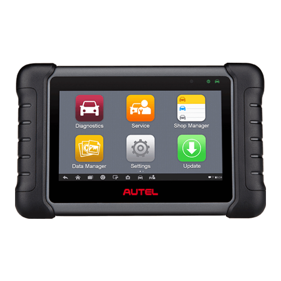
Vehicle Menu Layout When the tablet is properly connected to the vehicle, the platform is ready to start vehicle diagnosis. Tap on the Diagnostics application button on the MaxiCheck MX808 Job Menu to access the Vehicle Menu. Figure 4-1 Sample Vehicle Menu... -
Page 19: Top Toolbar Buttons
Top Toolbar Buttons The operations of the toolbar buttons at the top of the screen are listed and described in the table below: Table 4-1 Top Toolbar Buttons Button Name Description Home Returns to the MaxiCheck Job Menu. Displays a dropdown list; tap Auto Detect for auto VIN VIN Scan detection;... -
Page 20: Auto Vin Scan
Auto VIN Scan The MaxiCheck diagnostic system features the latest VIN-based Auto VIN Scan function to identify vehicles and scan all the diagnosable ECUs and run diagnostics on the selected system. This function is compatible with 2006 and newer vehicles ... -
Page 21: Manual Vin Input
Figure 4-4 Sample Diagnostic Screen The tool establishes communication with the vehicle and reads the control unit information. Choose Auto Scan to scan all the test vehicle available systems or tap Control Unit to access a specific system to diagnose. Figure 4-5 Sample Diagnostic Screen Manual VIN Input For vehicles that not supporting the Auto VIN Scan function, you may manually enter the... -
Page 22: Automatic Selection
Tap Done. Once the vehicle is identified, the Vehicle Diagnostics screen displays. Tap Cancel to exit Manual Input. Figure 4-6 Sample Diagnostic Screen Automatic Selection The Auto VIN Scan can be selected after selecting the test vehicle manufacturer. To perform Automatic Selection Tap the Diagnostics application button from the MaxiCheck Job Menu. -
Page 23: Manual Selection
Manual Selection When the vehicle’s VIN is not automatically retrievable through the vehicle's ECU, or the specific VIN is unknown, the vehicle can be manually selected. This mode of vehicle selection is menu driven, repeat the first two steps from the automatic selection operation and tap Manual Selection. - Page 24 Table 4-2 Diagnostics Toolbar Buttons Button Name Description Home Returns to the MaxiCheck Job Menu. Exits the diagnostic session of the currently Vehicle identified test vehicle and returns to the vehicle Swap menu screen. Settings Opens the settings screen. See Settings. Prints a copy of the displayed data.
- Page 25 To submit Data Logging reports in Diagnostics Tap the Diagnostics application button from the MaxiCheck Job Menu. The Data Logging button on the diagnostic toolbar is available throughout the Diagnostics operations. Tap the Data Logging button. The button displays blue during the active recording process.
-
Page 26: Making Selections
Warning Messages This type of messages displays a warning that a selected action may result in an irreversible change or loss of data. An example of this type of message is the “Erase Codes” message. Error Messages Error messages display when a system or procedural error has occurred. Examples of possible errors include a disconnection or communication interruption. -
Page 27: Auto Scan
Auto Scan The Auto Scan function performs a comprehensive scanning over all the ECUs in the vehicle to locate systems’ faults and retrieve DTCs. An example of the Auto Scan interface is pictured below: Figure 4-9 Sample Auto Scan Operation Screen Navigation Bar Main Section Function Buttons... -
Page 28: Control Unit
Column 4 — to perform further diagnosis or testing on a specific system item, tap the ○ > button to the right of that item. A Function Menu screen will display. Function Buttons A brief description of the operations of the Auto Scan’s Function Buttons’ are displayed in the table below. - Page 29 ECU Information — provides the retrieved ECU information in detail. An information screen opens upon selection. Trouble Codes — includes Read codes and Erase codes functions. Displays detailed information of DTC records retrieved from the test vehicle’s ECU and erases DTC records and other data from the test vehicle’s ECU.
- Page 30 Diagnostics Toolbar Buttons — see Table 4-2 Diagnostics Toolbar Buttons detailed descriptions of the operations for each button. Main Section — the left column displays the item names; the right column shows the specifications or descriptions. Function Button — ESC (or Back) button is available; tap it to exit after viewing. Trouble Codes Read Codes This function retrieves and displays the DTCs from the vehicle’s control system.
- Page 31 Erase Codes After reading the retrieved codes and making appropriate vehicle repairs, use this function to erase vehicle codes. To erase codes Tap Trouble Codes from the Function Menu, then tap Erase Codes. A warning message displays to advice of data loss if this function is completed. Tap Yes to continue.
- Page 32 Value Column — displays the values of the parameter items. Unit Column — displays the unit for the parameters. To change the unit mode, tap the Setting button on the top toolbar and select a required mode. See Unit for more information.
- Page 33 To edit the waveform color and line thickness in a data graph Select 1 to 3 parameter items to display in Waveform Graph mode. Tap the Zoom-in Button on the right to display the data graph in full screen. Select a parameter item on the left column.
- Page 34 Setting — tap this button to access setting screen to set the trigger mode, recording duration and threshold values for data recording, and define other control settings. Figure 4-14 Sample Setting Mode in Live Data There are four navigation buttons on top of the Setting mode screen. Selected Button —...
- Page 35 If the threshold limits are successfully set, two horizontal lines will appear on each of the data graphs (when Waveform Graph Mode is applied) to indicate the alarming point. The threshold lines are shown in different colors from the waveform of the parameters for distinction.
- Page 36 ECU data, or by monitoring the operation of the actuators. Such tests may include toggling between two positions of a solenoid, relay, or switch. Selecting Active Test opens a menu of test options that varies by make and model. Selecting a menu option activates the test. Follow the on-screen instructions to complete tests.
-
Page 37: Generic Obdii Operations
The main menu displays the supported special functions for the test vehicle. Follow the on-screen instructions to complete the test. When the operation is done, a message such as Completed, Finished or Successful displays. Tap the ESC button to exit the function. Figure 4-16 Sample Special Functions Screen Generic OBDII Operations A fast-access option for OBDII/EOBD vehicle diagnosis is available on the Vehicle Menu... -
Page 38: Function Descriptions
Select a specific protocol under the Protocol option. Wait for the OBDII Diagnostic Menu to appear. Figure 4-17 Sample OBDII Diagnostic Menu NOTE ○ Tapping the button displayed beside the function name opens a bubble with additional function information. Select a function option to continue. ... - Page 39 DTC & FFD When this function is selected, the screen displays a list of Stored Codes and Pending Codes. When the Freeze data of certain DTCs are available for viewing, a snowflake button will display on the right side of the DTC item. Figure 4-18 Sample DTC &...
- Page 40 the top prioritized DTC is the one for which the freeze frame records are retained. Freeze data includes a “snapshot” of critical parameter values at the time the DTC is set. Clear DTC This option is used to clear all emission related diagnostic data such as, DTCs, freeze frame data and manufacturer specific enhanced data from the vehicle’s ECM.
-
Page 41: Exiting Diagnostics
Vehicle Status This item is used to check the current condition of the vehicle, including communication protocols of OBDII modules, retrieved codes amount, status of the Malfunction Indicator Light (MIL), and other additional information. Exiting Diagnostics The Diagnostics application remains open as long as there is an active communication with the vehicle. -
Page 42: Service
Service The Service section is specially designed to provide you with quick access to the vehicle systems for various scheduled service and maintenance performances. The typical service operation screen is a series of menu driven executive commands. By following the on-screen instructions to select appropriate execution options, enter correct values or data, and perform necessary actions, the system will guide you through the complete performance for various service operations. - Page 43 NOTE For some vehicles, the scan tool can perform added functionality to reset additional service lights (maintenance cycle, service interval). Taking BMW as an example, its service reset function includes engine oil, spark plugs, front/rear brakes, coolant, particle filter, brake fluid, micro filter, vehicle inspection, exhaust emission inspection and vehicle check.
- Page 44 Figure 5-3 Sample Oil Reset Service Screen 1 On the next screen, the available items would be listed with three columns displayed: CBS value, availability, and service counter. Figure 5-2 Sample Oil Reset Service Screen 2 Tap on the value you want to reset and then tap the Reset button on the right bottom of the screen.
-
Page 45: Electronic Parking Brake (Epb) Service
Ensure that the EPB control system is reactivated after the maintenance work has been completed. NOTE Autel accepts no responsibility for any accident or injury arising from the maintenance of the Electronic Parking Brake system. To perform EPB functions Tap the Service application button from the MaxiCheck Job Menu. -
Page 46: Emf Start-Up
Follow the step-by-step on-screen instruction to complete the service. Press OK button to exit. EMF Start-up This service function would start up the parking brake, it must be conducted after the following repairs: Replacing an EMF control unit. Replacing the parking brake button. -
Page 47: Bms
In the following step, the screen will remind you that the fault memory of the parking brake control unit will be deleted, press Continue to proceed or the Back button on the bottom navigation bar to exit. Figure 5-8 Sample EMF Start-up Screen 3 Follow the on-screen instructions to pull the parking brake button and wait for around 3 seconds until the parking brake is set. -
Page 48: Register Battery Replacement
vehicles, please follow the on-screen instructions to make correct option selection. The vehicle may use either a sealed lead-acid battery or an AGM (Absorbed Glass Mat) battery. Lead acid battery contains liquid sulphuric acid and can spill when overturned. AGM battery (known as VRLA battery, valve regulated lead acid) also contains sulphuric acid, but the acid is contained in glass mats between terminal plates. - Page 49 Tap on the corresponding service you want to carry out. In this case, it is function 1 Display kilometer reading at last battery change and one before last. A notice screen displays. Figure 5-10 Sample BMS Screen 1 Read carefully the complete information and press Continue to continue. Figure 5-11 Sample BMS Screen 2 Check the battery capacity and the battery replacement information on the screen.
- Page 50 Tap on the corresponding function 1 to return to the selection screen or press the function 2 to end the service function. Figure 5-12 Sample BMS Screen 3 To register the battery replacement Tap on the corresponding service you want to carry out. In this case, it is function 2 Register battery replacement.
- Page 51 There are four functions listed: Enter battery replacement: Same capacity Enter battery replacement: Different capacity Enter battery replacement: Changing from the normal lead-acid battery (white housing) to AGM battery (black housing) End service function. Take the first function as an example. Read carefully the information on the screen and tap Yes to continue.
-
Page 52: Steering Angle Sensor (Sas) Service
Accident repairs where damage to the steering angle sensor or assembly, or any part of the steering system may have occurred NOTE AUTEL accepts no responsibility for any accident or injury arising from servicing the SAS system. When interpreting DTCs retrieved from the vehicle, always follow the manufacturer’s recommendation for repair. -
Page 53: Steering Angle Sensor Calibration
Before starting the procedure, make sure the vehicle has ESC. Look for the button on dash. Take Land Rover as an example. Tap the Service application button from the MaxiCheck Job Menu. Tap SAS button and wait for the vehicle manufacturer screen. You can tap VIN Scan or the vehicle make to acquire vehicle VIN information and tap Yes to confirm. -
Page 54: Dpf Service
Make sure the steering wheel is in the central position and the front wheels are in the straight position. Then tap OK to proceed. Figure 5-19 Sample SAS Function Screen 1 When the operation is completely finished, the scan tool will display a confirmation message. -
Page 55: Starting Basic Inspection Quantity
In the event of the car being driven in such a way that regeneration is not possible, i.e. frequent short journeys, a diagnostic trouble code will eventually be registered, DPF light and “Check Engine” indicator comes on. A service regeneration can be requested in the workshop, using the diagnostic tool. - Page 56 Tap Starting Basic Inspection Quantity from the service functions menu to enter the service screen. The tool communicates with the vehicle and reads the fault codes memory. Follow the on-screen instructions to finish this procedure. The tool will display a function list menu as below. Press the corresponding number button to perform the desired function.
-
Page 57: Injection Rate
[3]/[4] Store Data and Exit When the fuel delivery rate adjustment is completed, tap [3] to store the new value in the control units; or select [4] and OK to retain the old value. Injection Rate This function is used to adjust the injection volume. Tap Injection Rate from the service functions menu to enter the service screen. -
Page 58: Injector Rate Adjustment
NOTE The data you input should be in the reasonable range. If the input data is out of range, the tool will display a warning message “Permissible adjustment range exceeded.” [2] Reset Matching to 100% Once the [2] is pressed, the tool will automatically reset the value to 100%. [3] / [4] Store Data and Exit When the injection volume adjustment is completed, select [3] and OK to store the new value in the control units;... - Page 59 A series of instruction screens appears for users to perform the particle filter regeneration step by step. Follow the onscreen instructions and tap OK button until the tool reads off the regeneration status as below. Figure 5-27 Sample Regeneration Status Screen When the particle filter regeneration is complete, the tool will ask your confirmation to exit the display.
-
Page 60: Particle Filter Test
Particle Filter Test It is advisable to carry out a series of particle filter tests as a result of constant DPF regeneration, such as checking oil level, oil change interval for diesel contamination, swirl flaps, backpressure sensors and particle filter soot remains. Tap Particle filter test from the service functions menu. -
Page 61: Tire Pressure Monitor System (Tpms) Service
Tire Pressure Monitor System (TPMS) Service This function allows you to quickly look up the tire sensor IDs from the vehicle’s ECU, as well as to perform TPMS replacement and sensor test. Figure 5-30 Sample TPMS Screen Take Tire pressure sensor replacement (Front left wheel sensor) as an example. NOTE During this application the wheel unit 8 digit identifications will need to be entered using the screen displayed. -
Page 62: Immo Service
Enter the 8 digit sensor identification as required. Figure 5-32 Sample Sensor ID Input Screen The scan tablet will carry out the service and the screen will remind you the test has passed and all the selected tire pressure sensor identification numbers programmed successfully. - Page 63 it to a receiver in the vehicle's computer control module. If the code is correct, the computer allows the fuel supply and ignition systems to operate and start the car. If the code is incorrect or absent, the computer disables the system, and the car will be unable to start until the correct key is placed in the ignition.
- Page 64 Read the on-screen information carefully and follow the instructions to complete the operation. Figure 5-34 Sample Program Key FOB Screen...
-
Page 65: Shop Manager
Shop Manager The Shop Manager application helps you to manage the workshop information, customer information records, and keep test vehicle history records, which can be a great assist in dealing with daily workshop business and improves customer service. There are three main functions available: ... -
Page 66: Vehicle History
Button Name Description Done Completes editing and saves the file. Vehicle History This function stores records of test vehicle history, including vehicle information and the retrieved DTCs from previous diagnostic sessions, and displays all information in an easy-to-check table list, on which you can view summarized details and manually input other information about the test vehicle and diagnostic loggings, etc. -
Page 67: Historical Test Record
Historical Test Record The Historical Test record sheet of the tested vehicle is a detailed data form, which includes all general information of the vehicle such as vehicle year, make and model, etc., and the diagnostic trouble codes retrieved from the previous test sessions, as well as other service details which can be added manually by the technician himself. -
Page 68: Workshop Information
Workshop Information The Workshop Information form allows you to edit, input and save the detailed workshop information, such as shop name, address, phone number and other remarks, which, when printing vehicle diagnostic reports and other associated test file, will appear as the header of the printed documents. - Page 69 □ Tap the + photo frame beside the Name chart to add a photo. A sub menu displays, select Take Photo to take a new photo for the account, or select Choose Photo to choose from the existing files. Some customers may have more than one vehicle for service; you can always add new vehicle information to the account to be correlated.
-
Page 70: Data Manager
Data Manager The Data Manager application is used to store, print, and review the saved files. Most operations are controlled through the toolbar. Selecting the Data Manager application opens the file system menu. Different file types are sorted separately under different options, there are seven types of information files to be viewed or played back. -
Page 71: Image
Image The Image section contains all captured screenshot images. Figure 7-2 Sample Image Screen Toolbar Buttons — used to edit, print and delete the image files. See the following table for detailed information. Main Section — displays the stored images. Table 7-1 Toolbar Buttons in Image Button Name... -
Page 72: Report
To edit image information Tap the Data Manager application from the MaxiCheck Job Menu. Tap Image to access the image database. Select an image to display it in full screen. Tap the screen to display the editing toolbar. Tap the Info button to open a window displaying the image information. Tap the Edit button on the top right corner of the window. -
Page 73: Pdf
Figure 7-4 Sharing Report Screen 1 Tap View local reports to display it in full screen. Return to the Report List screen, tap the report and tap Report cloud sharing. Figure 7-5 Sharing Report Screen 2 Scan the QR code or tap Send Email or Send SMS to share the report. The PDF section stores and displays all PDF files of saved data. -
Page 74: Apps Uninstall
On the Review Data main screen, select a record file to playback. Figure 7-6 Sample Data Playback Screen Drop-down Toolbar — tap the button at the top center of the screen to open the Drop-down Toolbar. Main Section — displays the recorded data frames. Navigation Toolbar —... -
Page 75: Settings
Settings Selecting Settings application opens a setup screen, on which you can adjust default setting and view information about the MaxiCheck system. The following shows options available for the MaxiCheck system settings: Unit Language Printing Settings Report Settings ... -
Page 76: Printing Settings
Follow the instructions below to realize this function. To install the printer driver program to a PC Download the Maxi PC Suite from www.autel.com > Support > Downloads > Diagnostic Tool and install to your PC. Double click the setup.exe file. -
Page 77: Report Settings
To print via APP If a Wi-Fi printer is available, please purchase a Wi-Fi printer APP and install it onto your tablet. By a simple click on the Print button of a saved file on the tablet, the file will be printed automatically. Report Settings This option automatically synchronizes the diagnostics information of the vehicle to the vehicle history and forms a diagnostics report for user to upload. -
Page 78: Car Order
Tap the Auto Update option on the left column. The three auto update items list on the right. Switch the button of item that you want to auto update to ON. – Tap on the time to set time, you can use the button or tap on the numbers then the manual input screen will pop up. -
Page 79: About
Long press a specific app shortcut button displays the app menu, on which you can select and change the app shortcut. Press and drag the App Switcher icon around allows you to change the icon position alongside the edge of the screen. You may refer to Android documentation for additional information about Android system settings. -
Page 80: Update
Update The Update application allows you to download the latest released software. The updates can improve the MaxiCheck applications’ capabilities, typically by adding new tests, new models, or enhanced applications to the database. The tablet automatically searches for available updates for all of the MaxiCheck software when it is connected to the internet. - Page 81 ③ Main Section Left Column — displays vehicle logos. Middle Column — displays a brief introduction about the new changes to the software operation or capabilities. Tap button to open an information screen to view more details, and tap the dim area around to close the window. Right Column —...
-
Page 82: Support
If you already have an Autel account, sign in with your account ID and password, and skip to step 9. If you are a new member to Autel, click Register on the left side of the screen to create your Autel ID. -
Page 83: Support Screen Layout
Personal Info The User Info and Device Info are both included under the Personal Info section. User Info — displays detailed information of your registered on-line Autel account, such as your Autel ID, Name, Address and other contact information, etc. -
Page 84: Update Info
The Service Info section displays a detailed record list of the device’s service history information. Every time the device has been sent back to Autel for repair, the device’s serial number and the detailed repair information, such as the fault type, changed components, or system reinstallation, etc., will be recorded and updated to the... -
Page 85: User Profile
Tap OK to submit the post. To join and reply to a discussion post Select a forum group that you are interested in, whether by the product or the features, on the Communities Home screen. A list of the latest posts is displayed. Select a specific category on the Categories menu to better pinpoint the topics you are most interested with. -
Page 86: Training Channels
The Training section provides quick links to Autel’s online video accounts. Select a video channel by the language to see all the available online tutorial videos from Autel for various technical supports, such as product usage techniques and vehicle diagnostics practice, etc., may be available for your interests. -
Page 87: Academy
Academy Autel provides various tutorial articles and technical bulletins produced by top-notch technicians and product experts. Please view the materials that are saved on the tablet or view more technical articles from our online forum by clicking the links displayed under... -
Page 88: Remote Desk
You can use the application to receive ad-hoc remote support from Autel’s support center, colleagues, or friends, by allowing them to control your MaxiCheck tablet on their PC via the TeamViewer software. - Page 89 device. Tap Allow to accept, or tap Deny to reject. Refer to the associated TeamViewer documents for additional information.
-
Page 90: Maxifix
MaxiFix The MaxiFix application launches the on-line troubleshooter database, which not only provides you virtually all common diagnostic trouble code (DTC) database for most vehicles, but also serves as a forum allowing you to network with other MaxiCheck users, and gives you access to a vast database of repair and diagnostic tips along with proven filed fixes. -
Page 91: The Header
The Navigation Menu — the main menu at the bottom of the screen, which provides you access to different sections of MaxiFix. The Header The Header at the top of the screen features: A Select Vehicle button to open the vehicle identification window, and vehicle information bar, for example “2014 >... -
Page 92: Operations
To search for a MaxiFix Tip Select a Vehicle: Click the “Select Vehicle” button on the Header at the top of the screen. Select the year of the vehicle from the list. Select the make of the vehicle from the list. Select the model of the vehicle from the list. -
Page 93: Home
multiple makes. Search Fix — allows you to search for information from all available resources on MaxiFix, including: Open Questions, Tips, and Real Fixes, and displays search results. Ask — allows you to ask a question in the community. ... -
Page 94: Ask
Marked Posts — opens a list with links to Tips and discussions that you are actively participating in. My Profile — allows you to view your Autel account information including: your Autel ID, personal information, MaxiFix score, phone number and register time, and edit your portrait. -
Page 95: My Messages
allows you to limit the choices that displayed on the “Select Vehicle” list to specific years, and makes. Click “Set Year” or “Set Make” to set your preferred models. The preferred makes will also be displayed in the “Filter” options on the Home screen. Share a Tip —... - Page 96 indicates the total number of the new and unread messages. The displayed number will be reduced correspondingly after viewing. The message notification will appear under the following two conditions: Your question or answer is replied by other MaxiFix community members. Your answer is marked as the “Adopted!”...
-
Page 97: Support
A score of 1 is awarded to each of the first three respondents. Support Support, the last option on the Navigation Menu at the bottom of the screen, opens a screen that provides 2 ways to gain support from MaxiFix: A message form to contact the administrator of MaxiFix. -
Page 98: Quick Link
Quick Link The Quick Link application provides you with convenient access to Autel’s official website and many other well-known sites in automotive service, which offers you abundant information and resources, such as technical help, knowledge base, forums, training, and expertise consultations, etc. -
Page 99: Function Viewer
Function Viewer The Function Viewer allows you to search the functions supported by our tools and the version information. There are two ways of searching, either by searching the tool and the vehicle or searching the functions. To search by the vehicle Tap the Function Viewer application on the MaxiCheck Job Menu. - Page 100 To search by the functions Tap the Function Viewer application on the MaxiCheck Job Menu. The Function Viewer application screen displays. Tap the tool name on the top left to drop down the tool list, tap the one you want to search.
-
Page 101: Digital Inspection
Digital Inspection The Digital Inspection application configures the MaxiCheck Diagnostics Device to operate as a digital video scope by simply connecting the tablet to an Inspection Camera. This function allows you to examine difficult-to-reach areas normally hidden from sight, with the ability to record digital still images and videos, which offers you an economical solution to inspect machinery, facilities, and infrastructure in a safe and quick way. -
Page 102: Inspection Camera
Inspection Camera Figure 16-1 Inspection Camera ① Removable Imager Head Cable — connects to the tool when performing inspection for image and video viewing. ② Handgrip — ergonomically designed handle for comfortable grip and agile operation. ③ USB Cable — connects the Inspection Camera to the MaxiCheck tablet. Imager Head Accessories Figure 16-2 8.5 mm Imager Head Accessories ①... -
Page 103: Accessory Assembly
Figure 16-3 5.5 mm Imager Head Accessories ① Mirror — helps to look around corners and see the unreachable areas. ② Magnet — picks up small metal objects, such as dropped rings or screws. Accessory Assembly 8.5 mm Imager Head The three accessories, including the Magnet, Hook, and Mirror, can be attached to the Imager Head in the same manner described below: Hold the accessory and the imager head. -
Page 104: Technical Specifications
The two accessories, the Magnet and Mirror, can be attached to the Imager Head in the same manner described below: Hold the accessory and the imager head. Screw the thread part of the accessory over the imager head to fix the accessory. Technical Specifications Table 16-1 Technical Specifications Item... -
Page 105: Operations
Operations Before opening the Digital Inspection application, the imager head cable must be connected to the tablet using the USB cable. Install the correct imager head accessories according to the specific needs. NOTE When in operation, the imager head cable can be manipulated so as to better access confined or awkward spaces. - Page 106 Select the corresponding button on the upper-right corner to search or delete a video.
-
Page 107: Maintenance And Service
Maintenance and Service Maintenance Instructions The following shows how to maintain your devices, together with precautions to take. Use a soft cloth and alcohol or a mild window cleaner to clean the touch screen of the tablet. Do not use any abrasive cleansers, detergent, or automotive chemicals to the tablet. ... -
Page 108: Troubleshooting Checklist
You may be attempting to use the device in an overly hot/cold temperature. Try changing the charging environment. Your device may have not been connected to the charger properly. Check the connector. NOTE If your problems persist, please contact Autel’s technical support personnel or your local selling agent. -
Page 109: About Battery Usage
About Battery Usage Your tablet is powered by a built-in Lithium-ion Polymer battery. This means that, unlike other forms of battery technology, you can recharge your battery while some charge remains without reducing your tablet’s autonomy due to the “battery memory effect” inherent in those technologies. -
Page 110: Service Procedures
Technical Support If you have any question or problem on the operation of the product, please contact us (see the following contact info) or your local distributor. AUTEL NORTH AMERICA Phone:1-855-AUTEL-US(288-3587) Monday-Friday 9am-6pm EST Website: www.autel.com Email: sales@autel.com;... -
Page 111: Repair Service
Address: Office 1006-1010, Cluster C, Fortune Tower, Jumeirah Lakes Tower (JLT), Dubai, U.A.E Repair Service If it becomes necessary to return your device for repair, please download the repair service form from www.autel.com, and fill it in. The following information must be included: Contact name ... -
Page 112: Compliance Information
Compliance Information FCC Compliance FCC ID: WQ8-1610MX808 This device complies with Part 15 of the FCC rules and Industry Canada’s license- exempt RSSs. Operation is subject to the following two conditions: This device may not cause harmful interference. This device must accept any interference received, including interference that may cause undesired operation. -
Page 113: Sar
Changes or modifications not expressly approved by the party responsible for compliance could void the user’s authority to operate the equipment. The radiated output power of this device is below the FCC radio frequency exposure limits. Nevertheless, the device should be used in such a manner that the potential for human contact is minimized during normal operation. -
Page 114: Warranty
Warranty Limited One Year Warranty Autel Intelligent Technology Corp., Ltd. (the Company) warrants to the original retail purchaser of this MaxiCheck Diagnostic Device, that should this product or any part thereof during normal consumer usage and conditions, be proven defective in material...
Need help?
Do you have a question about the MaxiCheck MX808 and is the answer not in the manual?
Questions and answers