Table of Contents
Advertisement
Quick Links
DENTAL X-RAY
WARNING
This X-ray equipment may be dangerous to patient and operator unless safe
exposure factors, operating instructions and maintenance schedules are
observed.
OPERATOR'S
INSTRUCTIONS
· Wall Mount Type ................. WK
· Floor Mount Type ................ FK1/FK2
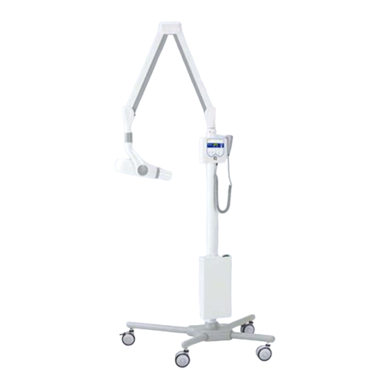
· Mobile Type ........................ FM
· Room Mount Type .............. RK
· Ceiling Mount Type ............. CK
505
0197
R
Advertisement
Table of Contents

Subscribe to Our Youtube Channel
Related Manuals for Belmont PHOT-X IIS 505


Summary of Contents for Belmont PHOT-X IIS 505
- Page 1 DENTAL X-RAY OPERATOR’S INSTRUCTIONS · Wall Mount Type ....WK · Floor Mount Type ....FK1/FK2 · Mobile Type ......FM · Room Mount Type ....RK · Ceiling Mount Type ..... CK 0197 WARNING This X-ray equipment may be dangerous to patient and operator unless safe exposure factors, operating instructions and maintenance schedules are observed.
-
Page 3: Table Of Contents
TABLE OF CONTENTS [1] INTRODUCTION ..............................1 [2] MAJOR COMPONENTS ............................ 3 [3] FUNCTION OF CONTROLS ..........................6 [4] OPERATING PROCEDURES ..........................9 [5] ESTIMATED AIR KERMA ........................... 9 [6] OPTIONAL HAND EXPOSURE SWITCH ......................9 [7] DIGITAL IMAGING SYSTEM ..........................10 [8] INFECTION CONTROL AND CLEANING ...................... -
Page 4: Introduction
INTENDED USE OF THE PRODUCT a. PHOT-X IIs 505 is an extraoral source dental radiographic x-ray unit. This unit is an active device intended to generate and control diagnostic purpose ionizing radiation. The absorption pattern of xray beam recorded on intraoral image receptor is used for general-purpose, routine, dental radiography examinations of diseases of the teeth, jaw and oral cavity structures. - Page 5 SYMBOLS In this book , on the labels or on the control panel of PHOT-X IIs 505, following symbols are used. Confirm the meanings of each symbol by the table below. Protection against Follow Instructions electric shock: Type ON (POWER)
-
Page 6: Major Components
[2] MAJOR COMPONENTS WALL MOUNT TYPE (WK) Main Power Switch X-Ray Head Cone Yoke Arm Collar Balance Arm Horizontal Arm Main Controller Sub Controller Hand Exposure Switch (Option) Fig.2-4 Major Components for WK FOOR MOUNT TY PE (FK1/FK2) Main Power Switch X-Ray Head Cone Yoke... - Page 7 MOBILE TYPE (FM) Main Power Switch X-Ray Head Cone Yoke Arm Collar Balance Arm Pole Bush Pole Pole Base Leg Bar (long) Leg Bar (Short) Lock Caster Standard Caster Main Controller Sub Controller Hand Exposure Switch WARNING Keep casters in the lock position, unless moving the equipment.
- Page 8 CEILING MOUNT TYPE (CK) Main Power Switch X-Ray Head Cone Yoke Arm Collar Balance Arm Swing Arm Swing Post Cover Ring Light Arm (Option) Ceiling Pole Main Controller Bracket Main Controller Ceiling Cover Ceiling Mounting Plate Sub Controller Hand Exposure Switch(Option) Support Ring Fig.2-5 Major Components for CK SUB CONTROLLER...
-
Page 9: Function Of Controls
= Film speed No. F.05 (equivalent to ISO speed group “F/E”, or Kodak InSight film) Including these two speeds, PHOT-X IIs 505 x-ray can provide 16 different film speeds (F.00~F.15) and any two of them can be programmed for easy selection. If doctor uses a different film speed, or prefers darker (or lighter) radiographs, the new speed can be programmed as foll Higher speed settings make films darker. - Page 10 3. To change the “b” setting from the factory default, F.05, push F switch momentarily until the “b” light illuminates. By depressing switch, increase or decrease film speed until the desired number for “b” setting is displayed. 4. Press T1 switch to store these settings, then turn the main power switch off. b.
- Page 11 TABLE 2. Speed Setting and Exposure Time (Long Cone) [ unit : sec.] Child Adult Large Adult Speed Setting 0.40 0.50 0.63 0.71 1.00 0.71 0.80 1.00 1.12 1.60 0.90 1.00 1.25 1.40 2.00 0.20 0.25 0.28 0.36 0.50 0.36 0.40 0.50 0.56 0.80 0.45 0.50 0.63 0.71 1.00 F.09 0.28 0.36 0.45 0.50 0.71 0.50 0.56 0.71 0.80 1.25 0.63 0.71 0.90 1.00 1.40 0.14 0.18 0.22 0.25 0.36 0.25 0.28 0.36 0.40 0.56 0.32 0.36 0.45 0.50 0.71...
-
Page 12: Operating Procedures
[4] OPERATING PROCEDURES 1. Turn ON the Main Power Switch 2. Confirm that Ready Light is illuminated. NOTE: The ready light will not illuminate unless the incoming line voltage is correct and within the x-ray’s operable range (207 ~ 253 Vac). 3. -
Page 13: Digital Imaging System
[7] DIGITAL IMAGING SYSTEM No x-ray image receptor is integrated into the PHOT-X IIs 505 x-ray system. If a receptor for digital imaging is used with PHOT-X IIs 505, the type and performance of the image receptor should be as follows. -
Page 14: Error Codes
[9] ERROR CODES If an abnormal condition exists in the unit, or a malfunction occurs, an error code is displayed in the Exposure Time Display Window. Please refer to the Table below. Error Code Condition Step to be Taken Possible Solution l the tooth selection lights Release the exposure switch Exposure switch was released before... -
Page 15: Maintenance
Maintenance personnel : Qualified dealer service personnel who has the experience with Belmont’s x-ray or has been trained by Belmont. But item 7 - 14 of the maintenace check list on page 13 should be verified routinely by treatment room personnel. - Page 16 Parameter Acceptance limit Frequency Procedures when failed OK/NG 7. Dosimetry Save the image that was Weekly If the image quality is taken under appropriate found poor comparing to a conditions as a reference reference image, check the image. condition of image receptor Compare a newly taken (film, sensor or imaging plate), image with a reference image...
-
Page 17: Technical Data
[11] TECHNICAL DATA 1. X-ray tube ------------------------------------------------------------ D-046 (Stationary Anode) a. Nominal focal spot value ----------------------------------------- 0.4 b. Target Material ---------------------------------------------------- Tungsten c. Target angle ------------------------------------------------------- 12.5 deg d. Maximum anode heat content ---------------------------------- 4.3 kJ (6.1 kHU) 2. Maximum x-ray tube assembly heat content --------------------- 293 kJ (413 kHU) 3. - Page 18 Nominal Radiation Output Table Nominal Radiation Output without Rectangular Collimator with Rectangular Collimator Exp. Time 60 kV 70 kV 60 kV 70 kV [sec.] Regular Cone Long Cone Regular Cone Long Cone Regular Cone Long Cone Regular Cone Long Cone 0.00 0.00 0.00...
-
Page 19: Electromagnetic Compatibility (Emc)
Portable RF communications equipment (including peripherals such as antenna cables and external antennas) should be used no closer than 30cm (12 inches) to any part of the PHOT-X IIs 505, including cables specified by the manufacturer. Otherwise, degradation of the performance of this equipment could result. - Page 20 (0, 45, 90, 135, 180, 225, hospital environment. If the user Voltage dips, short 270 and 315 degree) 270 and 315 degree) of the PHOT-X IIs 505 x-ray interruptions and 0 %Ut: 1 cycle 0 %Ut: 1 cycle requires continued operation...
-
Page 21: Other Information
4. Essential performance Unless the exposure switch is pressed, x-ray is not exposed. If the Essential performance is lost or deteriorated, the device may operate inadvertently and may harm the patient, the operator, and the surrounding people. [13] OTHER INFORMATION 1. -
Page 22: Label Location
[15] LABEL LOCATION (WK Type) (RK Type) (FM Type) F6.3AH, 250V (FM, FK, RK Type) (Type FK) (FM, FK, RK Type) (CK Type) (FM Type) - Page 23 COMP (WK, FM, FK and CK Type) COMP (WK and FK Type) COMP (RK Type) (FM Type)
- Page 24 NOTE TAKARA COMPANY EUROPE GmbH TAKARA BELMONT CORPORATION Berner Strasse 18, 60437 2-1-1, Higashishinsaibashi, Chuo-ku, Osaka, 542-0083, Japan Frankfurt am Main, Germany TEL: +81 6 6213 5945 Tel:+49 69 506878 0 TELEFAX: +81 6 6212 3680 BOOK NO. 1A0GDRR0 Fax:+49 69 506878 20...
Need help?
Do you have a question about the PHOT-X IIS 505 and is the answer not in the manual?
Questions and answers