Table of Contents
Advertisement
Quick Links
Advertisement
Table of Contents

Related Manuals for Belmont PRO III 047


Summary of Contents for Belmont PRO III 047
- Page 1 DRAFT PRO III 047 INSTALLATION INSTRUCTIONS...
-
Page 2: Table Of Contents
Table of Contents Safety Consideration Risk Level Interpretation ............3 Safety Precautions ..............5 Cautions regarding installation Precautions for installation ............6 Installation Dimensions ................7 Necessary tools and supplied parts ..........8 Necessary tools ............8 3-2-1 Supplied parts ............9 3-2-2 Installation procedures .............10 ... -
Page 3: Safety Consideration
Safety Consideration Risk Level Interpretation Precautions before use Make sure to carefully read the Safety Precautions and Operat- ing Precautions and use the product correctly. These precautions are intended to ensure the safe use of the product and prevent harm or damage to users or other people. According to the magnitude of harm and damage and the degree of urgency, an incident that may be caused by misuse of the product is classified into one of the following categories:... - Page 4 Safety Consideration The following graphical symbols are used to explain your responsibilities for using the product safely: Graphical symbols for prohibited activity Generally prohibited activity Disassembly, repair or modification prohibited Graphical symbol for mandatory instructions Mandatory instructions for ordinary users ...
-
Page 5: Safety Precautions
Safety Consideration Safety Precautions CONTRAINDICATION Installing or transferring the Precautions regarding installation product Do not install the product near electromagnetic sources such as communication facilities or elevators. Malfunction of this product may occur in the presence of electromagnetic interference waves. WARNING Installing or transferring the Precautions for installation... - Page 6 Cautions regarding installation 2-1 Precautions for installation 1. While carrying the chair, make sure to hold only the designated parts. If not, it may lead to physical injury. 2. Confirm that the fixing bolts are tightened before carrying the chair. 3.
-
Page 7: Installation
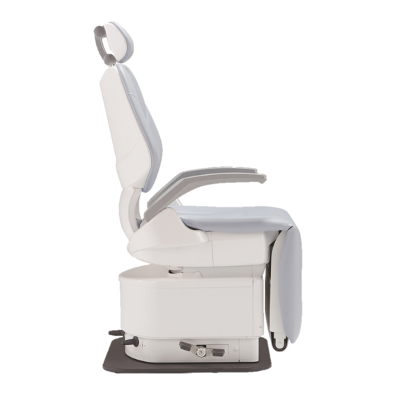
Installation 3-1 Dimensions 69-1/8 62-3/8 26-3/8 23-5/8 18-7/8 7-1/2 6-3/4 23-5/8 22-1/4 22-7/8 Unit: inch (Dimensional tolerance:±10%) *Dimensions and specifications are subject to change without notice. -
Page 8: Necessary Tools And Supplied Parts
Installation Necessary tools and supplied parts 3-2-1 Necessary tools The table below shows the necessary tools for the installation of this product. Tool name QTY. Phillips screwdriver No. 1–3 1 for each Monkey wrench (Max. opening width: 29 mm) 6-piece double head open end wrench set (5.5–24 mm) 8-piece hex key wrench set (1.5–8 mm) Level... -
Page 9: Supplied Parts
Installation 3-2-2 Supplied parts The table below shows the supplied parts included in the chair. Chair (unit) Part name QTY. Bolt cap Hex head flange screw TP-A, M8 × 30, black Countersunk screw, M5 × 8, plated Truss screw M4×6, plated Truss screw, M5×8, chrome-plated Headrest unit Headrest cover... - Page 10 Installation Installation instructions 1. Unpack the carton of the chair. Remove TP-A, M4 × 35, plated (10 pieces) for packing. 2. Remove the chair from the skid. Remove the hex coach bolts, M6 × 50, plated (4 pieces) that fix the base and skid. 3.
- Page 11 Installation 6. Attach the backrest. Fix the backrest with truss head screws, M5 × 8, chrome- plated (4 pieces). 7. Attach the headrest. (1) Pass the headrest cover to the headrest bar. (2) Attach the headrest to the headrest bar. Fix the headrest with the countersunk screws, M5 ×...
- Page 12 Installation 9. Attach the roll-up legrest. Fix the roll-up legrest with truss head screws M4×6, plated (2 pieces). 10. Attach the roll-up legrest cover. Fix the roll-up legrest cover with truss head screws M4×6, plated (4 pieces). 11. Attach the seat 12.
-
Page 13: Flow Diagram/Wiring Diagram 4-1 Flow Diagram
Flow Diagram/Wiring Diagram Flow Diagram... -
Page 14: Wiring Diagram
Flow Diagram/Wiring Diagram Wiring Diagram Auto Manual Manual STICK SWITCH PCB STICK SWITCH PCB STICK SWITCH PCB 1G01Q1** 1G01Q1** 1G01Q1** TL STICK SW(047) TL DOWN SAFE SW C 1A0RKS** 1A0P99** TL DOWN SAFE SW B TL STICK SW(047) 1A0RKS** 1A0P8Z** LED4 Light on when all function is locked LED5 Light on when limit mode Orange... - Page 15 NOTE...
- Page 16 Importer for U.S.A. BELMONT EQUIPMENT, Division of Takara Belmont USA, Inc. 101 Belmont Drive, Somerset, New Jersey 08873 U.S.A. TEL.:(732) 469-5000 / (800) 223-1192 FAX.:(732)526-6322 / (800) 280-7504 Importer for Canada TAKARA CO, CANADA LTD. 2076 S. Sheridan Way, Mississauga, Ont., L5J2M4, Can.
Need help?
Do you have a question about the PRO III 047 and is the answer not in the manual?
Questions and answers