Belmont BELRAY II 097 Installation Instructions Manual
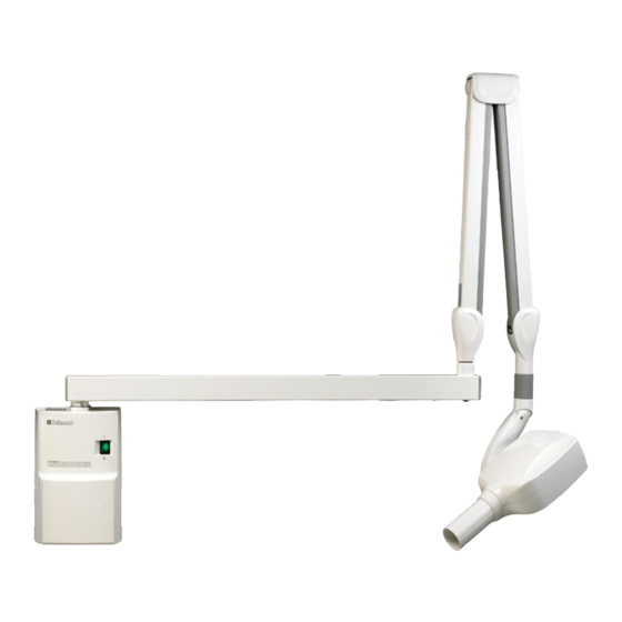
Dental x-ray
Hide thumbs
Also See for BELRAY II 097:
- Service manual (37 pages) ,
- Operator instructions manual (16 pages) ,
- Operator instructions manual (24 pages)
Table of Contents

Subscribe to Our Youtube Channel
Related Manuals for Belmont BELRAY II 097


Summary of Contents for Belmont BELRAY II 097
- Page 1 MODEL 097 DENTAL X-RAY INSTALLATION INSTRUCTIONS (for USA & Canada) WARNING This X-ray unit may be dangerous to patient and operator unless safe exposure factors, operating instructions and maintenance schedules are observed.
- Page 2 CAUTION This manual provides information and instructions for the installation, assembly calibration and certification procedures for BELMONT BELRAY II MODEL 097 dental x-ray. The instructions contained in this book should be thoroughly read and understood by dealer service personal before attempting to install the X-ray unit. After installation is completed, owners should...
-
Page 3: Table Of Contents
INDEX PAGE SECTION 1 : TECHNICAL DATA [1] ELECTRICAL AND RADIATION DATA -------------------------------------------------- 2 [2] PHYSICAL DIMENSIONS ------------------------------------------------------------------- 3 [3] TUBE HEAD THERMAL CHARACTERISTICS ----------------------------------------- 4 SECTION 2 : PRE-INSTALLATION INSTRUCTIONS [1] SUPPORT REQUIREMENTS ---------------------------------------------------------------- 5 [2] ELECTRICAL REQUIREMENTS ----------------------------------------------------------- 5 [3] LOCATION OF COMPONENTS ------------------------------------------------------------- 6 SECTION 3 : INSTALLATION INSTRUCTIONS [1] INSTALLATION REQUIREMENTS -------------------------------------------------------- 7... -
Page 4: Section 1 : Technical Data [1] Electrical And Radiation Data
SECTION 1 : TECHNICAL DATA [ 1 ] ELECTRICAL AND RADIATION DATA 1. X-ray tube ..............Toshiba D-0712 (Stationary Anode) a. Nominal focal spot value .......... 0.7 (IEC60366) b. Target material ............Tungsten c. Target angle ............... 16° d. Maximum anode heat content ........4.3kJ (6kHU) 2. -
Page 5: Physical Dimensions
[ 2 ] PHYSICAL DIMENSIONS ( ) =mm * 8-1/4" (215 mm) is the Pass-Thru Plate Width, if Optional 097PTP is ordered and Housing Side Panels are Removed. 5-5/8" (142) Max. 46-7/8" (1190) 31-1/2" 2-1/4" 3-3/16" Stroke 43-5/16" (1100) Maximum Reach (800) (80) (58) -
Page 6: Tube Head Thermal Characteristics
[ 3 ] TUBE HEAD THERMAL CHARACTERISTICS A. Interval between each exposure The temperature inside of the tube head rises when an exposure is made. The value of the heat generated is measured in Heat Units (HU), which is the product of tube potential, tube current and exposure time. -
Page 7: Section 2 : Pre-Installation Instructions [1] Support Requirements
SECTION 2 : PRE-INSTALLATION INSTRUCTIONS [ 1 ] SUPPORT REQUIREMENTS Main Controller : The main controller of model 097 has a wall plate designed for mounting on two 2 x 4 wood studs with 16 inches (406mm) centers. The wall and mounting hardware must be sufficient to withstand a 100 pound (45kg) shear load and a 450 pound (205kg) withdrawal force at each of the four (ø... -
Page 8: Location Of Components
[ 3 ] LOCATION OF COMPONENTS A. Main Controller, Arm and Head Assemblies : Using the information Provided in Fig.2-4, determine the correct location for the main controller. NOTE : State and local requirements supersede guide lines indicated below. ) : WITH LONG CONE Fig.2-4 Radius of Activity for X-ray Head B. -
Page 9: Section 3 : Installation Instructions
installer to record the necessary information onto the "ASSEMBLER'S INSTALLATION SECTION OF THE LIMITED WARRANTY REPORT FORM" supplied, which MUST be returned to BELMONT along with the warranty card. [ 1 ] INSTALLATION REQUIREMENTS Tools : Standard tool kit including 1.5 mm, 2 mm, 3 mm and 5 mm allen keys. -
Page 10: Main Controller And Arm Installation
[ 3 ] MAIN CONTROLLER AND ARM INSTALLATION The instructions given below are for mounting the main controller assembly on two 2 x 4 wood studs with 16 inch (406mm) centers. Should the BELRAY II MODEL 097 be mounted in a manner other than what is specified here, the wall and the strength of the hardware used must be checked and verified being adequate to withstand a 100 pound (45kg) shear load and a 450 pound (205kg) withdrawal force at each of the four (ø9 x 75mm) lag screws. - Page 11 Chassis C. CHASSIS OF MAIN CONTROLLER Interconnecting 1. Remove the restriction plate over the terminal Restriction Wires blocks by taking out two (M 4 x 8mm) screws. Plate (Fig.3-3) Wall Plate (M4x8) 2. Route electrical interconnecting wires Screw Electrical Wires (M4x8) Screw (M4x8)
- Page 12 Level 4. Place a level on the horizontal arm and confirm that the arm has same positive degree at its left, center and right swing positions. Horizontal (Fig.3-7) NOTE : Arm level will have a minor positive degree to compensate for head and arm weight.
- Page 13 Side Cover F.SIDE COVER ASSEMBLY 1. After the front panel of the main controller is installed, attach four hooks to the wall plate with (M4 x 6mm) screws supplied. 2. Side in the side covers from right and left side of the Wall Plate wall plate as the hooks catch the side covers.
-
Page 14: Head Assembly Installation
6. Insert the brake plug and brake screw (M6 x 6mm) Balance Arm into the horizontal arm collar. (Fig.3-13) Brake Plug Horizontal Do not fully tighten. Arm Collar Brake Screw Arm End Cap 7. Remove the end cap screw and open end cap from horizontal arm. - Page 15 Arm Holding Band 3. Making sure the stopper ring is placed on the CAUTION ! CAUTION ! yoke,insert the wiring from the balance arm DO NOT RELEASE DO NOT RELEASE THIS BAND UNTIL X-RAY HEAD IS assembly through the head shaft and into the THIS BAND UNTIL INSTALLED X-RAY HEAD IS...
-
Page 16: Sub Controller Installation
[ 5 ] SUB CONTROLLER INSTALLATION The wall and the strength of the hardware used must be checked and verified as being adequate to withstand a 10 pound (4.5kg) shear load. A flush mounted junction box with the necessary conduit and wiring should be pre-installed at 51-5/8"... -
Page 17: Hand Exposure Switch (Option)
[ 6 ] HAND EXPOSURE SWITCH (OPTION) An optional hand exposure switch can be connected Hook to the sub controller. Since this exposure switch has a coiled cord, operator can stand the most suitable position for peration. The exposure switch on the front panel of sub Tapping controller and this hand exposure switch can be used. -
Page 18: Section 4 : Post Installation Inspection [1] Arm Assembly
SECTION 4 : POST INSTALLATION INSPECTION [ 1 ] ARM ASSEMBLY 1. Incorrect leveling of the wall plate and wall bracket can cause arm drift. First, check leveling with horizontal arm in position #1. (Fig.4-1) If not correct, bracket must be adjusted by placing shims behind the wall plate. -
Page 19: Section 5 : Control Identification And Operation [1] Major Components And Control Identification
SECTION 5 : CONTROL IDENTIFICATION AND OPERATION [ 1 ] MAJOR COMPONENTS AND CONTROL IDENTIFICATION Fig.5-1 Major Components and Control Identification 1 Main Power Switch 10 Cone Type Selection Switch 2 Ready Light 11 Film Speed Selection Switch 3 Exposure Time Adjusting Switch (Down) 12 Digital Imaging Switch 4 Exposure Time Adjusting Switch (Up) 5 Tooth Selection Switch (T1) -
Page 20: Function Of Controls
Including these two speeds, BELRAY II Model 097 x-ray can provide 16 different film speeds (F.00 ~ F.15) and any two of them can be programmed for easy selection. If doctor uses a different film speed, or prefers darker (or lighter) radiographs, the new speed can be programmed as page 25. - Page 21 This setting should be adjusted according to the speed of the digital sensor or PSP (imaging plate) doctor uses as page 25. election witch election witch atient i e election witch →large adult →ad If the weight of child is less then 20kg, press →ch switch after setting to child.
-
Page 23: Error Codes
[ ] ERROR CODES If an abnormal condition exists in the unit, or a malfunction occurs, an error code is displayed in the Exposure Time Display Window (16). Please refer to the Table below. Error Condition Possible Solution Step to be Taken Code Release the exposure All the tooth selection... -
Page 24: Maintenance
Error Condition Possible Solution Step to be Taken Code Turn off the main power switch and wait for Contact customer Failure of electrical communication between approximately 2 min. E.22 service the power PCB and timer PCB. Turn on the main power switch again. -
Page 25: Section 6 : Post Installation Confirmation [1] Confirmation Of Power Supply Voltage
SECTION 6 : POST INSTALLATION CONFIRMATION [ 1 ] CONFIRMATION OF POWER SUPPLY VOLTAGE As specified in Electrical Requirements (page 5), power supply voltage must be within the operable range of 108 ~ 132 VAC. Confirm the power supply voltage again before turning on 1. -
Page 26: Confirmation Of Exposure Warning Lamp & Buzzer
[ 3 ] CONFIRMATION OF EXPOSURE WARNING LIGHT & BUZZER A. EXPOSURE WARNING BUZZER 1. Make an exposure and confirm that the exposure warning buzzer located within the sub controller is activated during the entire exposure. B. EXPOSURE WARNING LIGHT Exposure warning light is located on the front panel of the sub controller, 1. -
Page 27: Section 7 : Initial Setting [1] Speed Setting For Film And Digital Imaging
SECTION 7 : INITIAL SETTING [ 1 ] SPEED SETTING FOR FILM AND DIGITAL IMAGING A. FILM SPEED Prior to shipment of the x-ray from the factory, the following two film speeds are programmed to be selected by the Film Speed Selection Switch. In addition to these two speeds, x-ray can provide 16 different film speeds (F.00 ~ F.15) and any two of them can be programmed for easy selection. - Page 28 TABLE 1. Speed Setting and Exposure Time (7mA , Regular Cone) [unit : sec.] Patient Size Child Adult Large Adult Tooth TABLE 2. Speed Setting and Exposure Time (4mA , Regular Cone) [unit : sec.] Patient Size Child Adult Large Adult Tooth -26-...
- Page 29 TABLE 3. Speed Setting and Exposure Time (7mA , Long Cone) [unit : sec.] Patient Size Child Adult Large Adult Tooth TABLE 4. Speed Setting and Exposure Time (4mA , Long Cone) [unit : sec.] Patient Size Child Adult Large Adult Tooth -27-...
-
Page 30: Priority Of Selections
[ 2 ] PRIORITY OF SELECTIONS Factory default setting : Cone : Regular cone : off Film Speed : "d.08" Digital Imaging mA selection : 7 mA Patient Type : Adult If necessary, these settings can be changed. For example, if "D-speed" film is used for "Film a"... -
Page 31: Appendix 1 : Circuit Diagram
APPENDIX 1 : CIRCUIT DIAGRAM -29-... -
Page 32: Appendix 2 : Parts Identification [1] Arm And Head Assembly
APPENDIX 2 : PARTS IDENTIFICATION [ 1 ] ARM AND HEAD ASSEMBLY 10 (OPTION) Mats ID.No. Parts No. Description ID.No. Parts No. Description 1P01CBA0 X-RAY Head Assembly ECPE19F0 Left Cover for Joint No.3 Right Cover for Joint No.3 ECPE24C0 ECPE18F0 Yoke Inside Cover Joint No.3 1A037UA0... -
Page 33: Controller Assembly
[ 2 ] CONTROLLER ASSEMBLY OPTION Mats Mats Mats Mats ID.No. Parts No. Description ID.No. Parts No. Description 1A04BYA0 Wall Plate --------- Screw for Chassis (M4 x 10) ECPE34A0 Arm Mounting Bracket ECNR24A0 Hole plug for End Cap 1A0389A0 Chassis --------- Screw for Chassis (M4 x 6) 1A03Z6A0... -
Page 34: Appendix 3 : Certification
COMPLETED AND MAILED TO THE RESPECTIVE AGENCIES FOR THIS INSTALLATION TO BE CONSIDERED COMPLETE. ALSO COMPLETE THE WARRANTY CARD AND THE ASSEMBLERS INSTALLATION REPORT AND RETURN TO BELMONT EQUIPMENT CORP. REFER TO THE SAMPLE FORM : FOR FDA USE ONLY... - Page 35 NOTE...
- Page 36 BELMONT EQUIPMENT, Division of Takara Belmont, USA, Inc. 101 Belmont Drive Somerset, New Jersey 08873 U.S.A. TEL.:(732) 469-5000 / (800) 223-1192 Fax.:(732) 526-6322 / (800) 280-7504 www.belmontequip.com TAKARA COMPANY, CANADA, LTD. 2455 Meadowvale Boulevard, Mississauga, Ontario, L5N 5S2, Canada TEL.:(905) 816-8965 Fax.:(905) 816-8999...
Need help?
Do you have a question about the BELRAY II 097 and is the answer not in the manual?
Questions and answers