Table of Contents
Advertisement
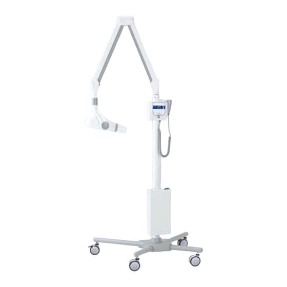
DENTAL X-RAY
WARNING
This x-ray equipment may be dangerous to patient and operator unless safe exposure factors,
operating instructions and maintenance schedules are observed.
CAUTION
This manual provides information and instructions for the installation, assembly, calibration and
certification procedures for BELMONT PHOT-X IIs 505 dental x-ray.
The instructions contained in this book should be thoroughly read and understood by dealer service
personal before attempting to install the X-ray unit. After installation is completed, owners should
file this manual and refer back to it to schedule periodic maintenance.
If this manual is lost or cannot be read by a damage, order the manual by the book number written
on the last page.
INSTALLATION
INSTRUCTIONS
Wall Mount Type...............WK
505
R
Advertisement
Table of Contents

Related Manuals for Belmont PHOT-X IIs 505


Summary of Contents for Belmont PHOT-X IIs 505
- Page 1 CAUTION This manual provides information and instructions for the installation, assembly, calibration and certification procedures for BELMONT PHOT-X IIs 505 dental x-ray. The instructions contained in this book should be thoroughly read and understood by dealer service personal before attempting to install the X-ray unit. After installation is completed, owners should file this manual and refer back to it to schedule periodic maintenance.
- Page 3 INDEX PAGE SECTION 1: TECHNICAL DATA [1] ELECTRICAL AND RADIATION DATA--------------------------------------------------------2 [2] PHYSICAL DIMENSIONS-------------------------------------------------------------------------3 [3] TUBE HEAD THERMAL CHARACTERISTICS-----------------------------------------------4 SECTION 2: PRE-INSTALLATION INSTRUCTIONS [1] SUPPORT REQUIREMENTS----------------------------------------------------------------------5 [2] ELECTRICAL REQUIREMENTS-----------------------------------------------------------------5 [3] LOCATION OF COMPONENTS------------------------------------------------------------------6 SECTION 3: INSTALLATION INSTRUCTIONS [1] INSTALLATION REQUIREMENTS--------------------------------------------------------------7 [2] UNPACKING------------------------------------------------------------------------------------------7 [3] MAIN CONTROLLER AND ARM INSTALLATION------------------------------------------8 [4] HEAD ASSEMBLY INSTALLATION-----------------------------------------------------------12...
-
Page 4: Electrical And Radiation Data
SECTION 1 : TECHNICAL DATA [ 1 ] ELECTRICAL AND RADIATION DATA 1. X-ray tube -------------------------------------------------- Toshiba D-046 (Stationary Anode) a. Nominal focal spot value ------------------------------ 0.4 (IEC60336) b. Target Material ------------------------------------------ Tungsten c. Target angle --------------------------------------------- 12.5° d. Maximum anode heat content ------------------------ 4.3kJ (6.1kHU) 2. -
Page 5: Physical Dimensions
[ 2 ] PHYSICAL DIMENSIONS unit : mm Max.1190 Stroke 1100 Maximum Reach 2122mm with 1000mm arm 1922mm with 800mm arm 1622mm with 500mm arm 1422mm with 300mm arm Location for Power Cable (See Max. Reach Chart) Cabinet Frame PHOT-X IIs Sub Controller for X-ray... -
Page 6: Tube Head Thermal Characteristics
[ 3 ] TUBE HEAD THERMAL CHARACTERISTICS A. Interval between each exposure The temperature inside of the tube head rises when an exposure is made. The value of the heat generated is measured in Heat Units (HU), which is the product of tube potential, tube current and exposure time. -
Page 7: Support Requirements
& & If the PHOT-X IIs 505 is to be mounted in a manner other than what is specified in this manual or if the hardware to be used is other than what is supplied, the support capability of the wall and the Fig.2-2 Sub Controller... -
Page 8: Location Of Components
[ 3 ] LOCATION OF COMPONENTS A. Main Controller, Arm and Head Assemblies : Using the information provided in Fig.2-4, determine the correct location for the main controller. NOTE : National and local requirements supersede guide lines indicated below. ( ) : WITH LONG CONE Fig.2-4 Radius of Activity for X-ray Head B. - Page 9 SECTION 3 : INSTALLATION INSTRUCTIONS [ 1 ] INSTALLATION REQUIREMENTS Tools : Standard tool kit including 1.5 mm, 2 mm, 3 mm and 5 mm allen keys. Instruments : -Digital multimeter with an accuracy of 1%, capable of measuring 300 V AC, and capable of indicating true RMS value within 1 sec.
-
Page 10: Main Controller And Arm Installation
[ 3 ] MAIN CONTROLLER AND ARM INSTALLATION The instructions given below are for mounting the main controller assembly on wood studs. Should the PHOT-XIIs 505 be mounted in a manner other than what is specified here, the wall and the strength of the hardware used must be checked and verified as being adequate to ø... - Page 11 Chassis B. CHASSIS OF MAIN CONTROLLER 1.Remove the restriction plate over the terminal Interconnecting Restriction Wires blocks by taking out two (M 4 x 8mm) screws. Plate ( Fig.3-3 ) (M4x8) Screw 2.Route electrical interconnecting wires and power supply wires through the access holes on chasis and mount the chassis on the arm bracket with Power Supply (M4x8)
- Page 12 4.Place a level on the horizontal arm and confirm that the arm is level throughout its left and right swing positions. (Fig.3-7) NOTE : Final leveling of horizontal arm is described on Page 16. 5.Connect 2P and 8P connectors of horizontal arm cable to the respective connectors on power PC Board.
- Page 13 F. BALANCE ARM ASSEMBLY W ARNING Horizontal Arm Do not release Arm holding band until the X-ray head has been installed. Bottom Balance arm assembly is spring loaded and can cause Cover equipment damage and injury if not handled in the (M3 x 8) Screw proper manner.
-
Page 14: Head Assembly Installation
7. Insert the brake plug and brake screw (M6 x 6mm) Balance Arm into the horizontal arm collar. (Fig.3-14) Brake Plug Horizontal Do not fully tighten. Arm Collar Brake Screw Arm End Cap 8. Remove the end cap from horizontal arm. Insert the stopper screw into upper threaded hole Horizontal inside horizontal arm and tighten securely. - Page 15 3. Making sure the stopper ring is placed on the Arm Holding Band yoke, insert the wiring from the balance arm assembly through the head shaft and into the yoke. (Fig.3-17) CAUTION ! CAUTION ! DO NOT RELEASE DO NOT RELEASE THIS BAND UNTIL X-RAY HEAD IS THIS BAND UNTIL...
-
Page 16: Sub Controller Installation
[ 5 ] SUB CONTROLLER INSTALLATION The wall and the strength of the hardware used must be checked and verified as being adequate to withstand a 10 pound (4.5kg) shear load. A flush mounted junction box with the necessary conduit and wiring should be pre-installed at 51-5/8"... -
Page 17: Hand Exposure Switch (Option)
[ 6 ] HAND EXPOSURE SWITCH (OPTION) An optional hand exposure switch can be connected Hook to the sub controller. Since this exposure switch has a coiled cord, operator can stand the most suitable position for peration. The exposure switch on the front panel of sub Tapping controller and this hand exposure switch can be used. -
Page 18: Arm Assembly
SECTION 4 : POST INSTALLATION INSPECTION [ 1 ] ARM ASSEMBLY 1. Incorrect leveling of the wall plate and wall bracket can cause arm drift. First, check leveling with horizontal arm in position #1. (Fig.4-1) If not correct, bracket must be adjusted by placing shims behind the wall plate. - Page 19 SECTION 5 : CONTROL IDENTIFICATION AND OPERATION [ 1 ] MAJOR COMPONENTS AND CONTROL IDENTIFICATION Fig.5-1 Major Components for WK Fig.5-2 Control Identification 1 Main Power Switch 10 Cone Type Selection Switch 2 Ready Light 11 Film Speed Selection Switch 3 Exposure Time Adjusting Switch (Down) 12 Digital Imaging Switch 4 Exposure Time Adjusting Switch (Up)
- Page 20 Long cone with rectangular collimator --> Short cone (Round) --> continued Including these two speeds, PHOT-X IIs 505 x-ray can provide 16 different film (F.00 ~ F.15) and any two of them can be programmed for easy selection. If doctor a different film speed, or prefers darker (or lighter) radiographs, the new speed can be programmed as follows.
- Page 21 2. Push F switch momentarily until the "a" light above the F switch illuminates. The exposure time display window shows the present film speed for "a" setting. (The factory default setting, F.09 should be displayed.) By depressing switch, increase or decrease film speed number until desired number for "a"...
-
Page 22: Estimated Air Kerma
TABLE 1. Speed Setting and Exposure Time (Reguler Cone) [ unit : sec.] Large Adult Speed Child Adult kV mA Setting 0.20 0.25 0.28 0.32 0.50 0.32 0.40 0.50 0.56 0.80 0.40 0.50 0.63 0.71 1.00 0.10 0.11 0.14 0.16 0.25 0.16 0.20... - Page 23 Turn NOTE : The ready light will not illuminate unless the incoming line voltage is correct and within the x-ray's operable range (rated line voltage ± 10%). NOTE : To manually set the exposure time, depress either of the Manual Exposure Time exposures when the unit is not in and Cone type...
-
Page 24: Error Codes
[ ] ERROR CODES If an abnormal condition exists in the unit, or a malfunction occurs, an error code is displayed in the Exposure Time Display Window !6 . Please refer to the Table below. Error Condition Possible Solution Step to be Taken Code All the tooth selection Release the exposure... -
Page 25: Maintenance
Maintenance personnel : Qualified dealer service personnel who has the experience with Belmont's x-ray or has been trained by Belmont. But item 6 - 9 of the maintenace check list on page 29 should be verified routinely by treatment room personnel. -
Page 26: Confirmation Of Power Supply Voltage
SECTION 6 : POST INSTALLATION CONFIRMATION [ 1 ] CONFIRMATION OF POWER SUPPLY VOLTAGE As specified in Electrical Requirements (page 5), power supply voltage must be within the operable range. (Rated line voltage ±10%). Confirm the power supply voltage again before turning on the unit. -
Page 27: Confirmation Of Kv And Ma
[ 4 ] CONFIRMATION OF KV and MA 1. Turn the main switch on and set the exposure time at 1 sec. and 60 kV, 3 mA. 2. Make an exposure and keep the exposure switch depressed continuosly after the exposure is over. 3. -
Page 28: Speed Setting For Film And Digital Imaging
= Film speed F.05 (equivalent to ISO speed group "F/E", or Kodak InSight Film) In addition to these two speeds, PHOT-X IIs 505 x-ray can provide 16 different film speeds (F.00 ~ F.15) and any two of them can be programmed for easy selection. If the doctor uses a different film speed, or prefers darker (or lighter) radiographs, the new speed can be programmed as follows. -
Page 29: Priority Of Selections
[ 2 ] PRIORITY OF SELECTIONS Factory default setting : Cone : Short cone Film Speed : off Digital Imaging : "d.10" kV selection : 60 kV mA selection : 6 mA Patient Type : Adult If necessary, these settings can be changed. For example, if "D-speed" film and long cone with rectangular collimator is used for pedodontistry, default settings for "Film", "Cone"... -
Page 30: Appendix 1: Circuit Diagram
APPENDIX 1 : CIRCUIT DIAGRAM... -
Page 31: Appendix 2: Maintenance Check List
APPENDIX 2 : MAINTENANCE CHECK LIST Parameter Acceptance limit Frequency Procedures when failed OK/NG 1. Line voltage Confirm the line voltage is within Yearly Connect to the power supply ±10% of rated voltage. Confirm within ±10% of rated voltage. the voltage drop during exposure Check disconnection of wire or is within 5% (for 100, 110, 120V) connection failure. -
Page 32: Controller Assembly
APPENDIX 3 : PARTS IDENTIFICATION [ 1 ] CONTROLLER ASSEMBLY Mats Mats Mats Mats -30-... - Page 33 ID.No. Parts No. Description 1A07R4A0 Wall Plate (small) (option ) ECPE34B0 Arm Mounting Bracket 1A0389B0 Chassis Power PC Board (100V) Power PC Board (110V) 1A0ERXA0 Power PC Board (120V) Power PC Board (220V) 1A0G4CA0 Power PC Board (230V) Power PC Board (240V) 1A0387A0 Restriction Plate 1A0386A0...
-
Page 34: Arm And Head Assembly
[ 2 ] ARM AND HEAD ASSEMBLY (OPTION) (OPTION) Mats ID.No. Parts No. Description 1S021CA0 X-Ray Head Assembly ECPE24C0 Yoke Yoke Inside Cover 1A037UA0 ------- Yoke Inside Cover Screw (M4 x 15) Head Housing Cover Set 1 set EHLL55A0 Yoke Side Cap ECQR60A0 Yoke Side Cap Screw (ø... - Page 35 NOTE...
- Page 36 NOTE TAKARA BELMONT CORPORATION 2-1-1, Higashishinsaibashi,Chuo-ku,Osaka, 542-0083, Japan TEL. : +81 6 6213-5945 TELEFAX : +81 6 6212-3680 Book No. 1A0GDSG0 Printed in Japan 2017-04...
Need help?
Do you have a question about the PHOT-X IIs 505 and is the answer not in the manual?
Questions and answers