Table of Contents
Advertisement
Quick Links
Advertisement
Table of Contents

Related Manuals for AgileX HUNTER2.0


Summary of Contents for AgileX HUNTER2.0
- Page 1 HUNTER2.0 USER MANUAL HUNTER 2.0 AgileX Robotics Team USER MANUAL V.2.0.2 2023.08 Document version Reviewe Version Date Edited by Notes Document creation, image 2023/03/12 吴忠义 V.2.0.0 update 2023/04/19 V.2.0.1 Sync GitHub commands 1 / 4 6...
- Page 2 If you have any questions about use, please contact us at support@agilex.ai . Please follow and implement all assembly instructions and guidelines in the chapters of this manual, which is very important.
- Page 3 Effectiveness and responsibility ● Make a risk assessment of the complete robot system. ● Connect the additional safety equipment of other machinery defined by the risk assessment together. ● Confirm that the design and installation of the entire robot system's peripheral equipment, including software and hardware systems, are correct.
- Page 4 Operation ● In remote control operation, make sure the area around is relatively spacious. ● Make sure to operate the Hunter 2.0 within the visual range. The maximum load of HUNTER 2.0 is 150KG. When in use, ensure that the payload does not exceed 150KG. ●...
- Page 5 ● Please do not charge the battery after its power has been depleted, and please charge the battery in time when low battery level alarm is on; ● Static storage conditions: The best temperature for battery storage is -10℃ to 45℃; in case of storage for no use, the battery must be recharged and discharged once about every 2 months, and then stored in full voltage state.
- Page 6 ● The temperature difference between day and night of recommended use environment should not exceed 25℃; Electrical/extension cords ● For the extended power supply on top, the current should not exceed 10A and the total power should not exceed 240W; ● For the extended power supply of top and tail, each ports must not be greater than 24V10A, the total output current must not be greater than 15A, total power should not exceed 360W.
-
Page 7: Table Of Contents
CONTENTS Document version Safety Information Attention CONTENTS 1 HUNTER 2.0 Introduction 1.1 Component list 1.2 Tech specifications 1.3 Requirement for development 2 The Basics 2.1 Status indication 2.2 Instructions on electrical interfaces 2.2.1 Top electrical interface 2.2.2 Rear electrical interface 2.3 Remote control instructions 2.4 Instructions on control demands and movements 3 Getting Started 3.1 Use and operation 3.2 Charging and battery replacement... -
Page 8: Hunter 2.0 Introduction
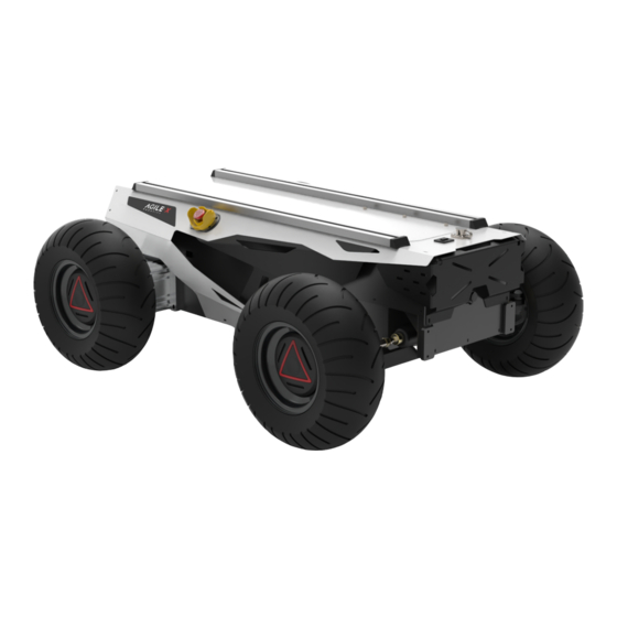
4 Q&A 5 Product Dimensions 5.1 Illustration diagram of product external dimensions 5.2 Illustration diagram of top extended support dimensions 1 HUNTER 2.0 Introduction HUNTER 2.0 is designed as a programmable UGV( UNMANNED GROUND CHASSIS) upon Ackermann model, of which the chassis is based on Ackermann steering. Therefore, it has similar characteristics to cars but has more significant advantages on Portland cement and asphalt roads over them. -
Page 9: Tech Specifications
1.2 Tech specifications Parameter Types Items Values L × W × H (mm) 980 × 745 × 370 Wheelbase (mm) Front/rear wheel base (mm) Weight of chassis body (kg) 65/70 Battery Type Lithium battery Battery parameters 24V 30Ah/60Ah Power drive motor DC brushless 2 ×400W Steering drive motor DC brushless 400W Power off... -
Page 10: Requirement For Development
Maximum speed (km/h) Minimum turning radius 33° (mm) Maximum gradeability (°) 10° Ground clearance (mm) 100mm Maximum battery life (h) 20KM (24V30Ah battery Maximum distance (km) 40KM (24V60Ah battery 3h (24V30Ah battery Charging time (h) 6h (24V60Ah battery Working temperature (℃) -10~40 Remote control Control Control mode... - Page 11 1 1 / 4 6...
-
Page 12: Status Indication
Designed as a complete intelligent module, HUNTER 2.0 combines inflatable rubber wheels with independent suspension as its power module, which, along with powerful DC brushless servo motor, enables the chassis of HUNTER 2.0 robot to flexibly move on different ground surfaces with high passing ability and ground adaptability. -
Page 13: Rear Electrical Interface
HUNTER 2.0 provides two 4-pin aviation connectors and one DB9 (RS232) connector. (The current version can be used for upgrade of firmware but do not support for command).The position of the top aviation connector and DB9 interface is shown in Figure 2.3. Figure 2.3 Schematic Diagram of HUNTER 2.0 Electrical Interface on Top HUNTER 2.0 has each aviation extension interface respectively on top and at rear end which is configured with a set of power supply and a set of CAN communication interface. -
Page 14: Remote Control Instructions
The extension interface at rear end is shown in Figure 2.6, where Q1 is the power display; Q2 is the switch of manual parking release; Q3 is the power switch; Q4 is the buzzer; Q5 is CAN and 24V power extension interface; Q6 is charging interface. Figure 2.6 Rear View Specific definitions for pins of Q5 are shown in Figure 2.7. - Page 15 The functions of the buttons are defined as follows: SWC and SWD are temporarily not enabled, among which SWA is the parking switch lever. Move it to the top to release the parking mode, and move it to the bottom to activate the parking mode (remote control can be performed normally only after the parking mode is released).
-
Page 16: Instructions On Control Demands And Movements
Remote control interface description: Hunter : model Vol: battery voltage Car: chassis status Batt: Chassis power percentage P: Park Remoter: remote control battery level Fault Code: Error information (Represents byte [5] in 211 frame) 2.4 Instructions on control demands and movements A reference coordinate system can be defined and fixed on the chassis body as shown in Figure 2.9 in accordance with ISO 8855. -
Page 17: Getting Started
Figure 2.9 Schematic Diagram of Reference Coordinate System for Chassis Body 3 Getting Started This section introduces the basic operation and development of the HUNTER 2.0 platform using the CAN bus interface. 3.1 Use and operation The basic operating procedure of startup is shown as follows: Check ●... - Page 18 ● Press Q3 button, and normally, the voltmeter will display correct battery voltage and front and rear lights will be both switched on; ● Check the battery voltage, the normally voltage range is 24~26.8V, if there is continuous b eep- “...
-
Page 19: Charging And Battery Replacement
● When the emergency stop is triggered, the parking will automatically start. At this time, released the emergency stop, no matter where the remote control SWA is located, it needs to be unlocked again for normal movement. If the power fails to be re-powered after a power failure (such as low battery voltage), you can use the Q2 knob switch to manually unlock the parking to facilitate moving the chassis or trailer. - Page 20 Battery replacement ● Turn off the power switch of the HUNTER 2.0 chassis. ● Press the button lock on the battery replacement panel and open the battery panel. ● Unplug the currently connected battery interface, respectively (XT60 power connector) (BMS connector) lock. ●...
-
Page 21: Development
3.3 Development HUNTER 2.0 provides CAN interfaces for user customization. Users can use it to conduct command control over the chassis body. 3.3.1 CAN message protocol HUNTER 2.0 adopts CAN2.0B communication standard which has a communication baud rate of 500K and Motorola message format. Though external CAN bus interface, the moving linear speed and the rotational angle of chassis can be controlled;... - Page 22 Decision- Steer-by-wire making control 0x211 100ms None chassis unit Data length 0×08 Position Function Data type Description 0×00 System in normal condition Current status byte [0] of chassis unsigned int8 0×01 Emergency stop mode body 0×02 System exception 0×00 Standby mode byte [1] Mode control unsigned int8...
- Page 23 Byte Meaning bit [0] Status error of drive (0: No failure 1: Failure) bit [1] Upper communication connection status (0: No failure 1: Failure) bit [2] Reserved, default 0 bit [3] Reserved, default 0 byte [4] bit [4] Reserved, default 0 bit [5] Reserved, default 0 bit [6]...
- Page 24 Command Movement Control Feedback Command Name Receive-timeout Sending node Receiving node Cycle (ms) (ms) Steer-by-wire Decision-making 0x221 20ms None chassis control unit Date length 0×08 Position Function Data type Description Moving speed byte [0] higher 8 bits Actual speed × 1000 (with an signed int16 Moving speed accuracy of 0.001m/s)
- Page 25 PS: In CAN command mode, it is necessary to ensure that the 0X111 command frame is sent with a cycle less than 500MS (recommended cycle is 20MS), otherwise HUNTER2.0 will determine that the control signal heartbeat is lost and report an error (0X211 feedback upper layer communication is lost), and the system will report an error After that, it will enter the standby mode.
- Page 26 Decision-making Chassis node 0x421 None None control unit Date length 0×01 Position Function Date type Description 0×00 Standby mode 0×01 CAN command mode byte [0] Control mode unsigned int8 Power-on enters standby mode default Description of control mode: In case the HUNTER 2.0 is powered on and the RC transmitter is not connected, the control mode is defaulted to standby mode.
- Page 27 0×00 Clear all not serious failure 0×01 Clear steering motor drive communication failure 0×02 Clear rear right motor drive communication failure 0×03 Clear rear left motor drive Errors clearing byte [0] unsigned int8 communication failure command 0×05 Clear battery under-voltage failure 0×06 Clear steering encoder communication failure...
- Page 28 Command Motor Drive High Speed Information Feedback Frame Name Receive-timeout Sending node Receiving node Cycle (ms) (ms) Steer-by-wire Chassis node 0x251~0x253 20ms None chassis Date length 0×08 Position Function Data type Description Motor speed byte [0] higher 8 bits Current speed of the motor Unit signed int16 byte [1] Motor speed...
- Page 29 Receive-timeout Sending node Receiving node Cycle (ms) (ms) Steer-by-wire Decision-making 0x261~0x263 100ms None chassis control unit Date length 0×08 Position Function Data type Description Drive voltage byte [0] higher 8 bits unsigned int16 Current voltage of drive unit 0.1V byte [1] Drive voltage lower 8 bits Drive...
- Page 30 bit [0] Whether the power supply voltage is too low (0:Normal 1:Too low) bit [1] Whether the motor is overheated (0:Normal 1:Overheated) bit [2] Whether the drive is over current (0:Normal 1:Over current) bit [3] Whether the drive is overheated (0:Normal 1:Overheated) byte [5] bit [4] Sensor status (0:Normal 1:Abnormal) bit [5] Drive error status (0:Normal 1:Error) bit [6] Drive enable status (0:Normal 1:Disability) bit [7] Reserved Parking control command is use to control the motor brake of the driving wheel. The detailed content of the protocol is as follows. Table 3.9 Parking control Command Command Name Parking Control Command...
- Page 31 Steering zero point setting and feedback instructions are used to calibrate the zero position. The specific content of the agreement is shown in Tables 3.10 and 3.11. Table 3.10 Steering zero point setting command Command Name Steering Zero Setting Command Receive-timeout Sending node Receiving node...
- Page 32 Command BMS Data Feedback Name Cycle Receive- Sending node Receiving node (ms) timeout (ms) Decision-making Steer-by-wire 0x361 500ms None control unit chassis 0×08 Date Date length Function Description type unsign byte [0] Battery SOC Range 0~100 ed int8 unsign byte [1] Battery SOH Range 0~100 ed int8...
- Page 33 Battery temperature byte [6] signed higher 8 bits Unit: 0.1°C byte [7] int16 Battery temperature lower 8 bits Table 3.13 BMS status feedback Command Name BMS Data Feedback Receive-timeout Sending node Receiving node Cycle (ms) (ms) Steer-by-wire Decision-making 0x362 500ms None chassis control unit...
- Page 34 Command Name Mileage Feedback Receive- Sending node Receiving node Cycle (ms) timeout (ms) Steer-by-wire Decision-making 0x311 20ms None chassis control unit Date length 0×08 Byte Function Data type Description Left wheel mileometer highest bit Left wheel mileometer byte [0] second-highest bit byte [1] Chassis left wheel mileometer signed int32...
- Page 35 Right wheel mileometer highest bit Right wheel mileometer byte [4] second-highest bit byte [5] Chassis right wheel mileometer signed int32 Right wheel feedback, unit:mm byte [6] mileometer byte [7] second-lowest Right wheel mileometer lowest bit The remote control information feedback frame is shown in Figure 3.15. Table 3.15 Remote control information feedback frame Command Name Remote Control Information Feedback Frame...
-
Page 36: Can Cable Connection
bit[0-1]: SWA:2- Up 3-Down bit[2-3]: SWB : 2-Up 1-Middle 3- Down unsigned int SW feedback byte[0] bit[4-5]: SWC : 2-Up 1-Middle 3- Down bit[6-7]: SWD 2-Up 3-Down byte [1] Alarm Status 2 signed int8 Range[-100,100] byte [2] Alarm Status 2 signed int8 Range[-100,100] byte [3] Warning Status 1 signed int8 Range[-100,100] byte [4] Warning Status 2 signed int8 Range[-100,100] 3.3.2 CAN cable connection... -
Page 37: Firmware Upgrades
In order to facilitate users to upgrade the firmware version used by HUNTER 2.0 and bring customers a more complete experience, HUNTER 2.0 provides a firmware upgrade hardware interface and corresponding client software. Upgrade Preparation ● Agilex CAN debugging module X 1 ● Micro USB cable X 1 ● HUNTER 2.0 chassis X 1 ●... - Page 38 3.Click the Load Firmware File button to load the firmware to be upgraded. If the loading is successful, the firmware information will be obtained, as shown in the figure 3 8 / 4 6...
- Page 39 4.Click the node to be upgraded in the node list box, and then click Start Upgrade Firmware to start upgrading the firmware. After the upgrade is successful, a pop-up box will prompt. 3 9 / 4 6...
-
Page 40: Hunter 2.0 Ros Package
● Thinkpad E470 notebook ×1 ● AGILEX HUNTER 2.0 mobile robot chassis ×1 ● AGILEX HUNTER 2.0 remote control FS-i6s ×1 ● AGILEX HUNTER 2.0 top aviation power socket ×1 Use example environment description ● Ubuntu 18.04 LTS ● ROS melodic ● Hardware connection and preparation ●... - Page 41 ROS installation and environment setting For installation details, please refer to http://wiki.ros.org/kinetic/Installation/Ubuntu Test CANABLE hardware and CAN communication Setting CAN-TO-USB adaptor ● Enable gs_usb kernel module 复 sudo modprobe gs_usb ● Setting 500k Baud rate and enable can-to-usb adaptor 复 sudo link can0 type can bitrate 500000 ● If no error occurred in the previous steps, you should be able to use the command to view the can device immediately 复...
- Page 42 Please refer to: https://github.com/agilexrobotics/agx_sdk https://wiki.rdu.im/_pages/Notes/Embedded-System/Li-nux/can-bus-in-linux.html AGILEX HUNTER 2.0 ROS PACKAGE download and compile ● Download ros package 复 sudo apt install -y ros-$ROS_DISTRO-teleop-twist-keyboard ● Clone compile hunter_ros code 复 $ cd ~/catkin_ws/src clone https://github.com/agilexrobotics/ugv_sdk.git $ git clone https://github.com/agilexrobotics/hunter_ros.git $ cd .. $ catkin_make Please refer to: https://github.com/agilexrobotics/hunter_2_ros Start the ROS node ●...
- Page 43 *_base:: The core node for the chassis to send and receive hierarchical CAN messages. Based on the communication mechanism of ros, it can control the movement of the chassis and read the status of the bunker through the topic. *_msgs: Define the specific message format of the chassis status feedback topic. *_bringup: startup files for chassis nodes and keyboard control nodes, and scripts to enable the usb_to_can module.
- Page 44 5.1 Illustration diagram of product external dimensions 5.2 Illustration diagram of top extended support dimensions 4 4 / 4 6...
- Page 45 4 5 / 4 6...
- Page 46 4 6 / 4 6...
Need help?
Do you have a question about the HUNTER2.0 and is the answer not in the manual?
Questions and answers