Table of Contents
Advertisement
Quick Links
Advertisement
Table of Contents

Subscribe to Our Youtube Channel
Related Manuals for AgileX TRACER


Summary of Contents for AgileX TRACER
- Page 1 TRACER User Manual TRACER AgileX Robotics Team User Manual V.2.0.2 2023.09 Document version Version Date Edited by Reviewer Notes Document creation, V.2.0.0 2023/03/12 吴忠义 image update V.2.0.1 2023/04/19 Sync GitHub commands 义 1 / 3 7...
- Page 2 TRACER integrators and end customers have the responsibility to ensure compliance with the applicable laws and regulations of relevant countries, and to ensure that there are no major dangers in the complete robot application. ...
- Page 3 In remote control operation, make sure the area around is relatively spacious. ● Carry out remote control within the range of visibility. ● The maximum load of TRACER is 100KG. When in use, ensure that the payload does not exceed 100KG. 3 / 3 7...
- Page 4 Please charge in time when the device voltage is lower than 22.5V. ● When TRACER has a defect, please immediately stop using it to avoid secondary damage. ● When TRACER has had a defect, please contact the relevant technical to deal with it, do not handle the ● defect by yourself.
- Page 5 Operational environment ● The operating temperature of TRACER outdoors is -10℃ to 45℃;please do not use it below -10℃ and above 45℃ outdoors; ● The requirements for relative humidity in the use environment of TRACER are: maximum 80%, minimum 30%;...
- Page 6 ● When handling and setting up, please do not fall off or place the vehicle upside down; ● For non-professionals, please do not disassemble the vehicle without permission. CONTENTS 6 / 3 7...
-
Page 7: Table Of Contents
CONTENTS Document version Safety Information Attention CONTENTS 1 TRACER Introduction 1.1 Component list 1.2 Tech specifications 1.3 Development requirements 2 The Basics 2.1 Status indication 2.2 Instructions on electrical interfaces 2.2.1 Rear electrical interface 2.3 Instructions on remote control 2.4 Instructions on control demands and movements 3 Getting Started 3.2 Charging... -
Page 8: Tracer Introduction
flexible indoor.Additional components such as stereo camera, laser radar, GPS, IMU and robotic manipulator can be optionally installed on TRACER for advanced navigation and computer vision applications. TRACER is frequently used for autonomous driving education and research, indoor and outdoor security patrolling and transportation, to name a few only. - Page 9 Front/rear wheel base (mm) Curb weight (kg) 28~30 Battery Type Lithium battery Battery parameters 24V 15Ah Power drive motor DC brushless 2 X 150W Steering drive motor Parking mode Servo brake/safety contact strip Steering Differential steering Swing arm non-independent Suspension form suspension Steering motor reduction ratio...
-
Page 10: Development Requirements
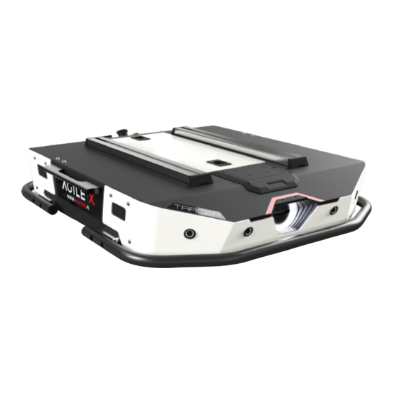
2.4G/extreme distance 200M System interface 1.3 Development requirements RC transmitter is provided (optional) in the factory setting of TRACER, which allows users to control the chassis of robot to move and turn; CAN interfaces on TRACER can be used for user ’ customization. 2 The Basics This section provides a brief introduction to the TRACER mobile robot platform, as shown in Figure 2.1 and Figure2.2. - Page 11 TRACER is Designed as a complete intelligent module, which along with powerful DC hub motor, enables the chassis of TRACER robot to flexibly move on flat ground of indoor. Anti-collision beams are mounted around the vehicle to reduce possible damages to the vehicle body during a collision.
-
Page 12: Status Indication
Water-proof connectors for DC power and communication interface is provided at the rear of TRACER, which not only allow flexible connection between the robot and external components but also ensures necessary protection to the internal of the robot even under severe operating conditions. -
Page 13: Instructions On Remote Control
FS remote control is an optional accessory for TRACER products. Customers can choose according to actual needs. Using the remote control can easily control the TRACER universal robot chassis. In this product, we use the design of the left-hand accelerator. Its definition and function can refer to Figure 2.6. - Page 14 SWC is the light control button. S1 is the throttle button. Control TRACER to move forward and backward; S2 controls rotation, and POWER is the power button. Press and hold at the same time to turn on and off the machine.
-
Page 15: Instructions On Control Demands And Movements
Figure 2.7 Schematic Diagram of Reference Coordinate System for Vehicle Body As shown in Figure 2.7, the vehicle body of TRACER is in parallel with X axis of the established reference coordinate system. Following this convention, a positive linear velocity corresponds to the forward movement of the vehicle along positive x-axis direction and a positive angular velocity corresponds to positive right-hand rotation about the z-axis. -
Page 16: Charging
Emergency stop ● After the chassis of TRACER mobile robot is started correctly, turn on the RC transmitter and select the remote-control mode. Then, TRACER platform movement can be controlled by the RC transmitter. -
Page 17: Communication Using Can
500K and Motorola message format. Via external CAN bus interface, the moving linear speed and the rotational angular speed of chassis can be controlled; TRACER will feedback on the current movement status information and its chassis status information in real time. - Page 18 0x00 System in normal condition Current status of byte [0] unsigned int8 0x01 Emergency stop mode vehicle body 0x02 System exception 0x00 Standby mode byte [1] Mode control unsigned int8 0x01 CAN command control mode 0x02 Remote control mode Battery voltage higher 8 bits Actual voltage X 10 (with an byte [2] byte [3]...
- Page 19 bit [6] Motor driver 2 lost connection bit [7] Reserved bit [0] Motor driver abnormality byte [5] bit [1:7] Reserved The command of movement control feedback frame includes the feedback of current linear speed and angular speed of moving vehicle body. For the detailed content of protocol, please refer to Table 3.3.
- Page 20 byte [6] Reserved 0x00 byte [7] Reserved 0x00 The control frame includes control openness of linear speed and control openness of angular speed. For its detailed content of protocol, please refer to Table 3.4. Table 3.4 Control Frame of Movement Control Command Command Name Control Command Receive-timeout Sending node Receiving node Cycle (ms) (ms)
- Page 21 The light control frame includes current state of front light. For its detailed content of protocol, please refer to Table 3.5. Table 3.5 Lighting Control Frame Command Name Lighting Control Frame Receive-timeout Sending node Receiving node Cycle (ms) (ms) Steer-by-wire Steer-by-wire 0x121 25ms...
- Page 22 Note[5]: This date only valid in custom mode The light control frame includes light control mode and control openness. For its detailed content , please refer to Table 3.6. Table 3.6 Lighting Control Frame Command Name Lighting Control Frame Receive- Sending node Receiving node Cycle (ms)
- Page 23 Count paritybit 0 - 255 counting loops, which will byte [7] unsigned int8 (count) be added once every command sent The control mode frame include set the control mode of chassis. For its detailed content , please refer to Table 3.7. Table 3.7 Control Mode Frame Instruction Command Name Control Mode Setting Frame...
- Page 24 Receive-timeout Sending node Receiving node Cycle (ms) (ms) Steer-by-wire Decision-making 0x441 None None chassis control unit Data length 0x01 Position Function Data type Description 0x00 Clear all errors byte [0] Control mode unsigned int8 0x01 Clear errors of motor 1 0x02 Clear errors of motor 2 Table 3.9 Odometer Feedback Instruction Command Name...
- Page 25 Left tyre lowest byte [3] odometer Right tyre highest byte [4] odometer Right tyre second byte [5] highest odometer Data of right tyre odometer signed int32 Unit mm Right tyre second byte [6] lowest odometer Right tyre lowest byte [7] odometer The chassis status information will be feed back; what s more, the information about motor.
- Page 26 Receive-timeout Sending node Receiving node Cycle (ms) (ms) Decision- Steer-by-wire making control uni 0x251~0x252 20ms None chassis Data length 0x08 Position Function Data type Description Motor rotational speed higher 8 byte [0] bits signed int16 Motor rotational speed Unit RPM byte [1] Motor rotational speed lower 8...
- Page 27 Decision- Steer-by-wire 0x261~0x262 100ms None making control unit chassis Data length 0x08 Position Function Data type Description byte [0] Reserved 0x00 byte [1] Reserved 0x00 byte [2] Reserved 0x00 byte [3] Reserved 0x00 byte [4] Reserved 0x00 byte [5] Driver status Details are shown in Table 3.12 byte [6] Reserved 0x00 byte [7] Reserved Table 3.12 Description of Failure Information Description of Failure Information byte [5] bit [0]...
-
Page 28: Can Cable Connection
Note:The maximum achievable output current is typically around 5 A. 3.3.3 Implementation of CAN command control Correctly start the chassis of TRACER mobile robot, and turn on FS RC transmitter. Then, switch to the command control mode, i.e. toggling SWB mode of FS RC transmitter to the top. At this point, TRACER chassis will accept the command from CAN interface, and the host can also parse the current state of chassis with the real-time data fed back from CAN bus. - Page 29 Upgrade Process 1.Plug in the USBTOCAN module on the computer, and then open the AgxCandoUpgradeToolV1.3_boxed.exe software (the sequence cannot be wrong, first open the software and then plug in the module, the device will not be recognized). 2.Click the Open Serial button, and then press the power button on the car body. If the connection is successful, the version information of the main control will be recognized, as shown in the figure.
- Page 30 4.Click the node to be upgraded in the node list box, and then click Start Upgrade Firmware to start upgrading the firmware. After the upgrade is successful, a pop-up box will prompt. 3 0 / 3 7...
-
Page 31: Scout2.0 Ros Package Usage Example
(such as sensing, control, status, planning, etc.) Currently ROS mainly support UBUNTU. Development Preparation Hardware preparation ● CANlight can communication module ×1 ● Thinkpad E470 notebook ×1 TRACER ● AGILEX mobile robot chassis ×1 TRACER ● AGILEX remote control FS-i6s ×1 TRACER ●... - Page 32 ● Hardware connection and preparation ● Lead out the CAN wire of the TRACER top aviation plug or the tail plug, and connect CAN_H and CAN_L in the CAN wire to the CAN_TO_USB adapter respectively; ● Turn on the knob switch on the TRACER mobile robot chassis, and check whether the emergency stop switches on both sides are released ●...
- Page 33 SCOUT 2.0 chassis 复 代 $ candump can0 ● Please refer to: https://github.com/agilexrobotics/agx_sdk https://wiki.rdu.im/_pages/Notes/Embedded-System/-Linux/can-bus-in-linux.html AGILEX TRACER ROS PACKAGE download and compile ● Download ros package 复 代 $ sudo apt install ros-$ROS_DISTRO-teleop-twist-keyboard $ sudo apt install ros-$ROS_DISTRO-joint-state-publisher-gui $ sudo apt install ros-$ROS_DISTRO-ros-controllers ●...
- Page 34 $ git clone https://github.com/agilexrobotics/ugv_sdk.git $ git clone https://github.com/agilexrobotics/tracer_ros.git $ cd .. $ catkin_make Please refer to https://github.com/agilexrobotics/tracer_ros Start the ROS node ● Start the based node 复 代 $ roslaunch tracer_bringup tracer_robot_base.launch ● Start the keyboard remote operation node 复 代 $ roslaunch tracer_bringup tracer_teleop_keyboard.launch Github ROS development package directory and usage instructions *_base:: The core node for the chassis to send and receive hierarchical CAN messages.
- Page 35 A:Normally, if TRACER can be controlled by a RC transmitter, it means the chassis movement is under proper control; if the chassis feedback frame can be accepted, it means CAN extension link is in normal condition. Please check the CAN control frame sent to see whether the data check is correct and whether the control mode is in command control mode.
- Page 36 3 6 / 3 7...
- Page 37 3 7 / 3 7...
Need help?
Do you have a question about the TRACER and is the answer not in the manual?
Questions and answers