AgileX SCOUT MINI User Manual
Hide thumbs
Also See for SCOUT MINI:
- User manual (43 pages) ,
- User manual (27 pages) ,
- User manual (24 pages)
Table of Contents
Advertisement
Quick Links
Advertisement
Table of Contents

Related Manuals for AgileX SCOUT MINI


Summary of Contents for AgileX SCOUT MINI
- Page 1 SCOUT MINI Research and Development Kit and Pro User Manual V.2.0.0 2021.04...
- Page 2 If you have any questions about use, please contact us at support@agilex.ai. Please follow and implement all assembly instructions and guidelines in the chapters of this manual, which is very important. Particular...
- Page 3 The design and use of the complete system need to comply with the safety requirements established in the standards and regulations of the country where the robot is installed. SCOUT MINI R&D kit integrators and end customers have the responsibility to ensure compliance with the applicable laws and regulations of relevant countries, and to ensure that there are no major dangers in the complete robot application.
-
Page 4: Table Of Contents
CONTENTS 0 Product Overview 3 Development Guide 3.1 ROS Development Introduction 1 Configuration list and Parameters 3.1.1 ROS History 1.1 SCOUT mini R&D kit Comparison 3.1.2 ROS Concept 1.2 Shipping List 3.1.3 ROS Node 1.2.1SCOUT MINI Lite 3.1.4 ROS Message 1.2.2SCOUT MINI Pro... -
Page 5: Product Overview
SCOUT MINI R&D Kit SCOUT MINI R&D Kit Pro SCOUT MINI Research&Development Kit & Pro is an entry-level version and advanced set of ROS developers developed and customized by Agliex Robotics for ROS scientific research and education applications. Integrated with high-performance industrial control, high-precision LiDAR and multiple sensors based on the Agliex Robot ROS ecosystem, which is capable to achieve applications such as mobile robot motion control, communication, navigation, map building, etc. -
Page 6: 2Scout Mini Pro
Nvidia Jetson Nano Intel RealSense D435 EAI G4 USB-HUB Router HD Display USB To CAN SCOUT MINI SCOUT MINI R&D Kit Configuration 1.2.2 SCOUT MINI R&D Kit Pro Name Quality Model Computing Unit Nvidia AGX Xavier Laser Sensor VLP -16 Vision Sensor... -
Page 7: Scout Mini Introduction
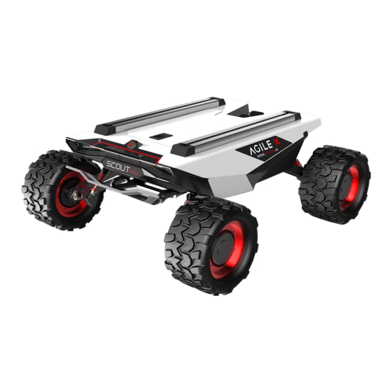
4WD, independent suspension, no turning radius and has made innovations in the design of the hub motor. The minimum turning radius of the chassis is 0m, and the climbing angle is close to 30 degrees. SCOUT MINI is half 50 % smaller than SCOUT, while still having excellent off-road performance. -
Page 8: Remote Control Operation
SWB switch the control mode, the SWC is controlling the light on and off while SWD controls the speed mode, the left rocker controls the Scout mini move forward and backward while the right rocker controls the rotation. Please note that the internal mapping motion of the chassis is mapped based on percentage, so when the joysticks are at the same position,the speed is constant. -
Page 9: Scout Mini Parameters
It contains multiple acceleration libraries for deep learning, computer vision, graphics and multimedia based on the comprehensive NVIDIA JetPack™ SDK. It is installed on the SCOUT MINI R&D Kit version and can be used to expand the applications of robot navigation and positioning, image processing, voice recognition and various other technologies. -
Page 10: Nvidia Xavier
1.5 Nvidia Xavier The NVIDIA Jetson AGX XAVIER Developer Kit is capable to run modern AI workloads and solve problems in optical inspection, manufacturing, robotics, logistics, retail, service, agriculture, smart cities, and healthcare. Plus, it delivers up to 32 TOPS and can operate in as little as 10 W. Jetson AGX Xavier Developer Kit is supported by NVIDIA JetPack, which includes a board support package (BSP), Linux OS, NVIDIA CUDA, cuDNN, and TensorRT software libraries for deep learning, computer vision, GPU computing, multimedia processing, and much more. -
Page 11: Intel Realsense D435
1.6 Intel RealSense D435 The Intel® RealSense™ depth camera D435 is a stereo solution, offering quality depth for a variety of applications. It's wide field of view is perfect for applications such as robotics or augmented and virtual reality, where seeing as much of the scene as possible is vitally important. -
Page 12: Hardware Installation And Electricity
2.1.1 SCOUT MINI R&D Kit The overall design of the SCOUT MINI R&D Kit research and education kit uses the stacking design and the frame is made of sheet metal, a high-definition display screen is installed at the rear part which is convenient for customers to develop and debug. -
Page 13: Scout Mini Pro
2.1.2 SCOUT MINI R&D Kit Pro The SCOUT MINI R&D Kit share the same basic design with SCOUT MINI R&D Kit, the difference between each other are the sensors location. The computing unit Nvida AGX Xavier is at the bottom of the holder, the USB-HUB with independent power supply is located at the second layer along with USB to CAN module and Intel RealSense D435 . -
Page 14: Scout Mini Pro
2.2.2 SCOUT MINI R&D Kit Pro The following figure is the external connection of Nvidia Jetson Nano. Nano's network port is connected to the router's network port which is designed for remote desktop control to access and debug, also it is easy to expand other network devices. -
Page 15: Development Guide
3 Development Guide 3.1 ROS Development Introduction 3.1.1 ROS History Robot Operating System (ROS or ros) is an open source robotics middleware suite. Although ROS is not an operating system but a collection of software frameworks for robot software development, it provides services designed for a heterogeneous computer cluster such as hardware abstraction, low-level device control, implementation of commonly used functionality, message-passing between processes, and package management. -
Page 16: Ros Service
When the product is ready for shipping, the sensor holder is separated from the Scout MINI. User need to use tool to set the sensor holder on the Scout MINI. Firstly, put the four slider nuts into the slide way each side on the Scout MINI , and then use... -
Page 17: Hd Display Installation
When the product is ready for shipping, the sensor holder is separated from the Scout MINI. User need to use tool to set the sensor holder on the Scout MINI. Firstly, put the four slider nuts into the slide way each side on the Scout MINI , and then use the hexagonal tool to screw corresponding four screws on the holder to the platform. -
Page 18: Before Start Up
SCOUT MINI R&D Kit Pro Put the HD display into the display holder horizontally, as shown in the figure below. Then settle the display holder with screws and nylon posts to the holes on both sides. -
Page 19: Scout Mini Pro
Press the power button on the Scout MINI, as shown in the figure below. After pressing the power button of the Scout MINI , the computing unit will automatically log in and show the following interface, the root authority password and system login password are agx If you need to shut down he system, do not press the power button directly because thel computing unit is running. - Page 20 If you need to shut down he system, do not press the power button directly because thel computing unit is running. Enter the command $poweroff in the terminal or click shut down of the drop-down menu, as shown in the figure below, wait until the display shows no signal input, then press the power button to shut down the system.
-
Page 21: Scout Mini R&D Kit Development
(Ubuntu, ROS, Gazebo, RVIZ) Ubuntu 16.04 Ubuntu 18.04 kinetic melodic Gazebo Gazebo RVIZ RVIZ 3.4.1 Download the corresponding operating system remote desktop software on the host computer Open the wireless network settings of the host computer, it shows that there are two signals from the router GL-AR750 (respectively), please connect to the 5G frequency band, the default password is goodlife 3.4.2 Xavier or Nano Connection(make sure the computer unit is power on) - Page 22 3.4.2.2 Click Yes 3.4.2.3 Username: agilex Password: choose save password 3.4.2.4 keep clicking OK...
- Page 23 3.4.2.5 Enter default password 3.4.2.6 Connection successful...
- Page 24 3.4.3.1 Enter the router, the default address is 192.168.8.1 select the language and set the password 3.4.3.2 Click USE as LAN port...
-
Page 25: Ros Installation
3.4.3.3 Successfully set to LAN port mode, now you can connect the Kit with the host computer through a network cable for access Install Source sudo sh -c 'echo "deb http://packages.ros.org/ros/ubuntu $(lsb_release -sc) main" > /etc/apt/sources.list.d/ros-latest.list' Or the source from China sudo sh -c '. -
Page 26: Sensors Base Node
Ubuntu18.04 sudo apt-get install ros-melodic-desktop-full Dependency sudo rosdep in rosdep update Environment set up Ubuntu16.04 echo "source /opt/ros/kinetic/setup.bash" >> ~/.bashrc source ~/.bashrc Ubuntu18.04 echo "source /opt/ros/melodic/setup.bash" >> ~/.bashrc source ~/.bashrc Install rosinstall, sudo apt install python-rosinstall python-rosinstall-generator python-wstool build-essential Enable gs _usb sudo modprobe gs_usb Open CAN port and set the baud rate sudo ip link set can0 up type can bitrate 500000... - Page 27 Testing the hardware by using can-utils sudo apt install can-utils Command testing # receiving data from can0 $ candump can0 # send data to can0 $ cansend can0 001#1122334455667788 scout_bringup: Start up the mobile base node. scout_base: Control and monitor package based on ugv_sdk。 scout_description: scout_min URDF model, available for simulation of customized robots equipped with sensors scout_msgs:scout_mini message format definition。...
-
Page 28: Navigation And Positioning Based
Fixed frame choose camera_link Fills in the corresponding topic in image component to get the rgb picture... - Page 29 Get the rgb+Depth map roslaunch realsense2_camera rs_camera.launch Open rviz, click the add to add DepthCloud component Fixed frame choose camera_link, choose the corresponding topic in the Depth Map topic. The depth map in shown below.
- Page 30 ydlidar_ros: Start the EAI-G4 single-line lidar function package, and users can set some parameters of the radar according to specific application scenarios. Show the scan result of the lidar cd ydlidar/launch roslaunch ydlidar lidar_view.launch Start lidar, publish base_link-><laser_link> coordinate transfer roslaunch scout_bringup open_rslidar.launch velodyne_driver: Processing raw point cloud data and laser data function package velodyne_laserscan: base on velodyne_driver package,...
- Page 31 Start lidar, publish base_link-><laser_link> coordinate transfer roslaunch scout_bringup open_rslidar.launch Move_base is the core algorithm of robot navigation path planning. It subscribes to the positioning data of lidar /scan, map, /odom mileage and amcl, and then uses the path planning plugin integrated into move_base.
- Page 32 ROS SLAM Algorithm: gmapping: Lidar/scan data and odometer/odom data are required, using PF (Particle Filter). hector : Based on the optimized algorithm (solving the least squares problem), the advantages and disadvantages: no odometer is required, but the radar frame rate requires a very high rate at 40Hz, and the estimated 6-degree-of-freedom pose can adapt to the situation of uneven air or ground.
- Page 33 SLAM Mapping: (1) Start the lidar and publish the coordinate transformation of base_link-><laser_link> roslaunch scout_bringup open_rslidar.launch (2) Start gmapping mapping node roslaunch scout_bringup gmapping.launch (3) Use the remote control to control the Kit to move around the scene. After building the map, save the map to the specified directory (usually /description) rosrun map_server map_saver ‒f ~/catkin_ws/scout _base/scout_description/maps/map Autonomous Navigation:...
- Page 34 (3) Regulate the actual position of the robot on the map displayed in rviz, and regulate the chassis rotation by publishing an approximate position with the handle. When the laser shape overlaps with the scene shape in the map, the regulation is complete. After setting the positioning, the laser shape and the scene shape in the map have basically overlapped, the means the regulation is complete.
- Page 35 (4) Set multiple target points on the multi-point navigation plug-in in the left column, click Start Navigation, and switch the SWB to command control mode. The target point is generated, as the picture shown below.
- Page 36 Click to start navigation, the map has generated a path (in green), and it will automatically navigate to the target point Take the VLP-16 radar as an example. The VLP-16 radar is a 16-line lidar. In 2° increments, 16° up and down respectively.
- Page 37 SLAM Mapping: (1) Start the lidar and publish the coordinate transformation of base_link-><laser_link> roslaunch scout_bringup open_rslidar.launch (2) Start gmapping mapping node roslaunch scout_bringup gmapping.launch Note: If you need to choose different map, please open the navigation.launch file to modify the parameters which is marked with red line as shown in the figure below.
- Page 38 (3) Use the remote control to control the Kit to move around the scene. After building the map, save the map to the specified directory (usually /description) rosrun map_server map_saver ‒f ~/catkin_ws/scout _base/scout_description/maps/map Autonomous Navigation: (1) Start the lidar and publish the coordinate transformation of base_link-><laser_link> roslaunch scout_bringup open_rslidar.launch (2)...
- Page 39 After setting the positioning, the laser shape and the scene shape in the map have basically overlapped, the means the regulation is complete. As the picture shown below. (4) Set multiple target points on the multi-point navigation plug-in in the left column, click Start Navigation, and switch the SWB to command control mode.
- Page 40 The target point is generated, as the picture shown below. Click to start navigation, the map has generated a path (in green), and it will automatically navigate to the target point.
- Page 41 Official distributor WORLDWIDE david.denis@generationrobots.com +33 5 56 39 37 05 www.generationrobots.com...
Need help?
Do you have a question about the SCOUT MINI and is the answer not in the manual?
Questions and answers