
Related Manuals for AgileX BUNKER MINI 2.0


Summary of Contents for AgileX BUNKER MINI 2.0
- Page 1 BUNKER MINI 2.0 User Manual BUNKER MINI AgileX Robotics Team User Manual V.2.0.1 2023.09 Document version Edited Version Date Reviewer Notes V1.0.0 2023/1/15 何士玉 first draft 1 / 3 8...
- Page 2 first time. You can contact us at support@agilex.ai if you have any questions about usage. It is very important that all assembly instructions and guidelines in other chapters of this manual are followed and implemented. Particular attention should be paid to text associated with warning...
- Page 3 Safety Information The information in this manual does not include the design, installation and operation of a complete robotic application, nor does it include any peripherals that may affect the safety of this complete system. The design and use of this complete system requires compliance with the safety requirements established in the standards and specifications of the country where the robot is installed.
- Page 4 ● If the vehicle does not have an individually customized IP protection level, the vehicle's waterproof and dustproof capabilities are IP67. Inspection ● Make sure that each device has sufficient power. ● Make sure there is no obvious abnormality in the vehicle. ●...
- Page 5 ● Charging: You must use the matching dedicated lithium battery charger for charging. Do not charge the battery below 0°C. Do not use non-original standard batteries, power supplies, and chargers. Precautions for use environment ● The working temperature of BUNKER MINI is -10℃~40℃. Please do not use it in environments with temperatures below -10℃...
-
Page 6: Table Of Contents
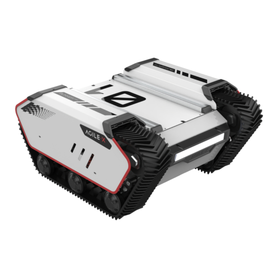
C ontrol command and motion description G etting Started U se and operation C harging D evelopment 3.3.1 CAN Cable Connection 3.3.2 CAN protocol description 3.3.3 BUNKER MINI 2.0 ROS Package Usage Example 4 Use and operation 6 / 3 8... - Page 7 5 Q&A 6 Product Dimensions 6.1 Illustrations of product outline dimensions 6.2 Illustrations of top expansion bracket dimensions I ntroduction of BUNKER MINI 2.0 BUNKER MINI 2.0is an all-round tracked chassis vehicle for industrial applications. It is featured with simple and sensitive operation, large development space, adaptability to development and application in various fields, IP67 dustproof and waterproof, and great gradeability, etc.
- Page 8 Wheelbase (mm) Front/rear wheel base (mm) Chassis height Track width Curb weight (kg) Battery Type Lithium battery Battery parameters 30AH Power drive motor 2×250W DC brush motor Steering drive motor Parking mode Steering Track type differential steering Suspension form Steering motor reduction ratio Steering motor encoder Drive motor reduction ratio...
- Page 9 Besides, BUNKER MINI 2.0 is equipped with a CAN interface, through which users can conduct secondary development. T he Basics This part will give a basic introduction to the BUNKER MINI 2.0 mobile robot chassis, so that users and developers can have a basic understanding of BUNKER MINI 2.0chassis. E lectrical interface description ...
- Page 10 Figure2.1 Rear electrical interface The definition of the communication and power interface of Q5 is shown in Figure 2-2. Function and Pin No. Pin Type Remarks Definition Positive power supply, voltage range 24~29V, Power maximum current 10A Power Negative power supply CAN_H CAN bus high 1 0 / 3 8...
- Page 11 CAN_L CAN bus low Figure 2.2 Pin definition diagram of the rear aviation extension interface R emote control instructions The Fuss remote control is an optional accessory for BUNKER MINI products. Customers can choose according to actual needs. Using the remote control can easily control the BUNKER MINI universal robot chassis.
- Page 12 Figure 2.3 Schematic diagram of FS remote control buttons Remote control interface description: Bunker : model Vol: battery voltage Car: chassis status Batt: Chassis power percentage P: Park Remoter: remote control battery level Fault Code: Error information (Represents byte [5] in 211 frame) 1 2 / 3 8...
- Page 13 8855 standard as shown in Figure 2.4. Figure 2.4 Schematic diagram of the vehicle body reference frame As shown in 2.4, the BUNKER MINI 2.0 body is parallel to the X-axis of the established reference frame. 1 3 / 3 8...
-
Page 14: Etting Started
G etting Started This part mainly introduces the basic operation and use of the BUNKER MINI 2.0 platform, and introduces how to carry out the secondary development of the vehicle body through the external CAN port and the CAN bus protocol. -
Page 15: C Harging
Basic operation process of remote control ● After the BUNKER MINI 2.0 robot chassis is started normally, turn on the remote control and select the control mode as the remote control mode, so that the motion of BUNKER MINI 2.0 platform can be controlled by the remote control. -
Page 16: D Evelopment
● depends on the status indication of the charger. D evelopment 3.3.1 CAN Cable Connection BUNKER MINI is shipped with the vehicle and provides a male aviation plug as shown in Figure 3.1. The definition of the wires is yellow as CANH, blue as CANL, red as power positive, and black as negative. - Page 17 Table 3.1 BUNKER MINI 2.0 Chassis State Feedback Frame Command name System state feedback command Receiving Sending node Receiving Node Cycle ms Timeout (ms) Wire-controlled Decision control 0x211 200ms None chassis unit Data length 0x08 Location Function Data Type Description 0x00 System normal...
- Page 18 Table 3.2 Explanation table of fault information Fault information description Byte Meaning bit [0] Battery undervoltage fault bit [1] Battery undervoltage warning Remote control disconnection protection 0: bit [2] normal, 1: remote control disconnection bit [3] Reserved, default 0 byte [5] Drive 2 communication fault bit [4] (0: no fault, 1: fault)
- Page 19 Data length 0x08 Location Function Data Type Description The upper eight bits of the byte [0] movement speed Actual speed X 1000 (accurate to signed int16 0.001m/s) The lower eight byte [1] bits of the movement speed The upper eight bits of the byte [2] rotation speed...
- Page 20 Data length 0x08 Position Function Data Type The upper eight byte [0] bits of the linear velocity Travel speed of the vehicle body, signed int16 unit mm/s, value range [-1300,1300] The lower eight byte [1] bits of the linear velocity The upper eight bits of byte [2] the angular...
- Page 21 Note[1] Control mode description When the remote control for BUNKER MINI 2.0 is not turned on, the default control mode is the standby mode, and you need to switch to the command mode to send the motion control command. If the remote control is turned on, it has the highest authority and can block the control of commands.
- Page 22 Note 3: Example data, the following data is for testing use only 1. The vehicle moves forward at a speed of 0.15/S byte [0] byte [1] byte [2] byte [3] byte [4] byte [5] byte [6] byte [7] 0x00 0x96 0x00 0x00 0x00...
- Page 23 The upper eight byte [2] bits of motor current Current motor current signed int16 unit 0.1A The lower eight bits of byte [3] motor current The current position of the byte [4] signed int16 motor is the highest The current position of the byte [5] signed int16 motor is the...
- Page 24 Data length 0x08 Position Function Data type Description The upper eight byte [0] bits of driver voltage Current driver voltage signed int16 unit0.1v The lower eight byte [1] bits of driver voltage The upper eight byte [2] bits of driver temperature signed int16 unit 1℃...
- Page 25 Whether the driver is over-temperature (0: normal 1: over- bit [3] temperature) bit [4] Sensor state (0: normal 1: abnormal) bit [5] Driver error state (0: normal 1: abnormal) bit [6] Driver enabling state (0: Enabling 1: Disabling) bit [7] Reserved Table 3.10 Odometer Feedback Frame Command name...
- Page 26 The lowest bit of byte [3] the left wheel odometer The highest bit of the byte [4] right wheel odometer The second highest bit of the byte [5] right wheel The odometer feedback of the odometer right wheel of the chassis signed int32 Unit mm The second lowest bit of the byte [6]...
- Page 27 bit[0-1]: SWA 2-up 3-down bit[2-3]: SWB 2-up 1-mid 3-down Remote control byte [0] unsigned int8 SW feedback bit[4-5]: SWC 2-up 1-mid 3-down bit[6-7]: SWD 2-up 3-down Right joystick byte [1] signed int8 Value range [-100,100] left and right Right joystick up byte [2] signed int8 Value range [-100,100]...
- Page 28 Battery SOC byte [0] State of unsigned int8 Range 0~100 Charge Battery byte [1] SOH (State of unsigned int8 Range 0~100 Health) High order byte byte [2] of battery voltage unsigned int16 Unit: 0.01 V Low order byte byte [3] of battery voltage High order byte byte [4] of battery current...
-
Page 29: Bunker Mini 2.0 Ros Package Usage Example
(such as sensing, control, state, planning, etc.). Currently ROS mainly supports UBUNTU. Development preparation Hardware preparation ● CANlight can communication module X1 ● Thinkpad E470 Laptop X1 ● AGILEX BUNKER MINI 2.0 mobile robot chassis X1 2 9 / 3 8... - Page 30 ● Hardware connection and preparation ● Pull out the CAN line of the BUNKER MINI 2.0 4-core aviation or rear plug, and connect the CAN_H and CAN_L in the CAN line to the CAN_TO_USB adapter respectively; ● Turn on the chassis knob switch of the BUNKER MINI 2.0 mobile robot, and check whether the emergency stop switches on both sides are released;...
- Page 31 TITAN. 复 代 candump can0 ● Please refer to: https://github.com/agilexrobotics/agx_sdk https://wiki.rdu.im/_pages/Notes/Embedded-System/-Linux/can-bus-in-linux.html AGILEX BUNKER ROS PACKAGE Download and compile Download ros dependencies ● 复 代 sudo apt install -y ros-$ROS_DISTRO-teleop-twist-keyboard Clone and compile the bunker_ros source code ●...
-
Page 32: Use And Operation
*_bringup: startup files for chassis nodes and keyboard control nodes, and scripts to enable the usb_to_can module 4 Use and operation In order to facilitate users to upgrade the firmware version of BUNKER MINI 2.0 and bring to customers more perfect experience, BUNKER MINI 2.0 provides the hardware interface for firmware upgrade and the corresponding client software. - Page 33 Upgrade Preparation ● Agilex CAN debugging module X 1 ● Micro USB cable X 1 BUNKER MINI chassis X 1 ● ● A computer (WINDOWS OS (Operating System)) X 1 Upgrade Process 1.Plug in the USBTOCAN module on the computer, and then open the AgxCandoUpgradeToolV1.3_boxed.exe software (the sequence cannot be wrong, first open the software and then plug in the module, the device will not be recognized).
- Page 34 4.Click the node to be upgraded in the node list box, and then click Start Upgrade Firmware to start upgrading the firmware. After the upgrade is successful, a pop-up box will prompt. 3 4 / 3 8...
- Page 35 A: Under normal circumstances, if BUNKER MINI 2.0 can be controlled by the remote control, it means that the chassis motion control is normal, and it can receive the feedback frame of the chassis, which means that the CAN extension link is normal. Please check whether the command is switched to CAN control mode..
- Page 36 Q: When the relevant communication is carried out through the CAN bus, and the chassis feedback command is normal, why does the car do not respond after the control is issued? A: BUNKER MINI 2.0 has a communication protection mechanism inside. Chassis has a timeout protection mechanism when dealing with external CAN control commands. Assuming that after the vehicle receives a frame of communication protocol, it does not receive the next frame of control commands for more than 500MS, and it will enter the communication protection with a speed of 0, so the command from the host computer must be periodically issued.
- Page 37 3 7 / 3 8...
- Page 38 3 8 / 3 8...
Need help?
Do you have a question about the BUNKER MINI 2.0 and is the answer not in the manual?
Questions and answers