AgileX SCOUT 2.0 User Manual
Hide thumbs
Also See for SCOUT 2.0:
- User manual (30 pages) ,
- User manual (39 pages) ,
- User manual (48 pages)
Table of Contents
Advertisement
Quick Links
Advertisement
Table of Contents

Related Manuals for AgileX SCOUT 2.0


Summary of Contents for AgileX SCOUT 2.0
- Page 1 SCOUT 2.0 AgileX Robotics Team User Manual 2021.03 V.2.1.0...
- Page 2 If you have any questions about use, please contact us at support@agilex.ai. Please follow and implement all assembly instructions and guidelines in the chapters of this manual, which is very important. Particular...
- Page 3 Use SCOUT2.0 always under -10℃~45℃ ambient temperature. This robot does not have a complete autonomous mobile robot, If SCOUT 2.0 is not configured with separate custom IP including but not limited to automatic anti-collision, anti-falling, protection, its water and dust protection will be IP22 ONLY.
-
Page 4: Table Of Contents
1.3 Requirement for development 3.4.3 Serial protocol content 3.5 Firmware upgrades 2 The Basics 3.6 SCOUT 2.0 SDK 2.1 Status indication 3.7 SCOUT 2.0 ROS Package 2.2 Instructions on electrical interfaces 2.2.1 Top electrical interface 4 Attention 2.2.2 Rear electrical interface 4.1 Battery 2.3 Instructions on remote control... -
Page 5: Scout 2.0 Introduction
1.3Requirement for development FS RC transmitter is provided (optional) in the factory setting pf SCOUT 2.0, which allows users to control the chassis of robot to move and turn; CAN and RS232 interfaces on SCOUT 2.0 can be used for user’ s customization. -
Page 6: The Basics
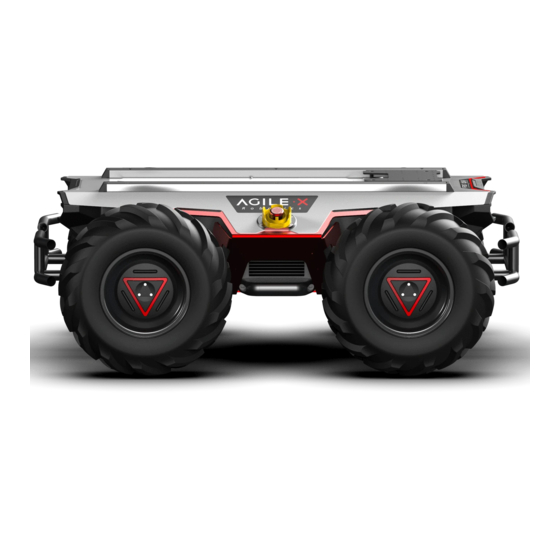
2 The Basics This section provides a brief introduction to the SCOUT 2.0 mobile robot platform, as shown in Figure 2.1 and Figure 2.2. 1.Front View 2.Stop Switch Figure 2.1 Front View 3.Standard Profile Support 4.Top Compartment 5.Top Electrical Panel 6.Retardant-collision Tube... -
Page 7: Status Indication
Figure 2.3 Schematic Diagram of SCOUT 2.0 Electrical Interface on Top SCOUT 2.0 has an aviation extension interface both on top and at rear end, each of which is configured with a set of power supply and a set of CAN communication interface. These interfaces can be used to supply power to extended devices and establish communication. -
Page 8: Rear Electrical Interface
It should be noted that, the extended power supply here is internally controlled, which means the power supply will be actively cut off once the battery voltage drops below the pre-specified threshold voltage. Therefore, users need to notice that SCOUT 2.0 platform will send a low voltage alarm before the threshold voltage is reached and also pay attention to battery recharging during use. -
Page 9: Instructions On Remote Control
Figure 2.9 Schematic Diagram of Reference Coordinate System for Vehicle Body As shown in Figure 2.9, the vehicle body of SCOUT 2.0 is in parallel with X axis of the established reference coordinate system. In the remote control mode, push the remote control stick S1 forward to move in the positive X direction, push S1 backward to move in the negative X direction. -
Page 10: Getting Started
SCOUT 2.0 vehicle body; Basic operating procedure of remote control: After the chassis of SCOUT 2.0 mobile robot is started correctly, turn on the RC transmitter and select the remote-control mode. Then, SCOUT 2.0 platform movement can be controlled by the RC transmitter. -
Page 11: Can Cable Connection
Correctly start the chassis of SCOUT 2.0 mobile robot, and turn on DJI RC transmitter. Then, switch to the command control mode, i.e. toggling S1 mode of DJI RC transmitter to the top. At this point, SCOUT 2.0 chassis will accept the command from CAN interface, and the host can also parse the current state of chassis with the real-time data fed back from CAN bus. - Page 12 Table 3.2 Description of Failure Information Description of Failure Information Byte Meaning Battery undervoltage fault (0: No failure 1: Failure) Protection voltage is 22V bit [0] (The battery version with BMS, the protection power is 10%) Battery undervoltage fault[2] (0: No failure 1: Failure) Alarm voltage is 24V bit [1] (The battery version with BMS, the warning power is 15%) bit [2]...
- Page 13 0×01 CAN command mode enable Description of control mode: In case the SCOUT 2.0 is powered on and the RC transmitter is not connected, the control mode is defaulted to standby mode. At this time, the chassis only receives control mode command, and does not respond other commands. To use CAN for control need to switch CAN command mode at first.
- Page 14 [Note 3] Example data: The following data is only used for testing 1.The vehicle moves forward at 0.15m/s byte [0] byte [1] byte [2] byte [3] byte [4] byte [5] byte [6] byte [7] 0x00 0x96 0x00 0x00 0x00 0x00 0x00 0x00 2.The vehicle steering 0.2rad/s...
- Page 15 Table 3.8 Motor temperature, voltage and status information feedback Motor Drive Low Speed Information Feedback Frame Command Name Sending node Receiving node Cycle (ms) Receive-timeout (ms) Steer-by-wire chassis Decision-making control unit 0x261~0x264 20ms None Date length 0×08 Position Data type Function Description byte [0]...
- Page 16 Table 3.10 Light Control Frame Command Name Light Control Frame Cycle (ms) Receive-timeout (ms) Sending node Receiving node Decision-making control unit Chassis node 0x121 20ms None Date length 0×08 Position Function Date type Description 0x00 Control command invalid byte [0] Light control enable flag unsigned int8 0x01 Lighting control enable...
- Page 17 Table 3.12 System Version Information Enquiry Frame System Version Information Enquiry Command Command Name Sending node Cycle (ms) Receive-timeout (ms) Receiving node Decision-making control unit 0x411 None None Chassis node Date length 0×01 Position Date type Description Function Constant 0×01 byte [0] Enquire system version unsigned int8...
- Page 18 Table 3.15 Remote Control Information Feedback Remote Control Information Feedback Frame Command Name Sending node Receiving node Cycle (ms) Receive-timeout(ms) None 0x241 Steer-by-wire chassis Decision-making control unit 20ms Date length 0×08 Description Byte Function Data type bit[0-1]: SWA:2- Up 3-Down bit[2-3]: SWB : 2-Up 1-Middle 3-Down byte[0] SW feedback...
-
Page 19: Serial Communication Protocol
3.4 Serial Communication Protocol 3.4.1 Instruction of serial protocol It is a standard for serial communication jointly formulated by the Electronic Industries Association (EIA) of the United States in 1970 conjunction with Bell Systems, modem manufacturers and computer terminal manufacturers. Its name is "Technical Standard for Serial Binary Data Exchange Interface Between Data Terminal Equipment (DTE) and Data Communication Equipment (DCE)". - Page 20 Protocol Content Command Name System Status Feedback Frame Sending node Receiving node Cycle (ms) Receive-timeout (ms) Steer-by-wire chassis Decision-making control unit 100ms None Frame length 0×0C Command type Feedback command(0×AA) Command ID 0×01 Data length Data type Description Position Function 0×00 System in normal condition unsigned int8 byte [0]...
- Page 21 Movement Control Feedback Command Command Name Movement Control Feedback Command Receiving node Sending node Cycle (ms) Receive-timeout (ms) Decision-making control unit Steer-by-wire chassis 20ms None 0×0C Frame length Feedback command (0×AA) Command type 0×02 Command ID Data length Function Data type Description Position Moving speed higher 8 bits...
- Page 22 Control Mode Setting Command Command Name Control Mode Setting Command Sending node Receiving node Cycle (ms) Receive-timeout (ms) Decision-making control unit Chassis node None None Frame length 0×05 Command type Control command (0×55) Command ID 0×02 Data length Position Function Date type Description 0×00 Standby mode...
- Page 23 Motor Drive High Speed Information Feedback Frame Command Name Motor Drive High Speed Information Feedback Frame Receiving node Sending node Cycle (ms) Receive-timeout (ms) Chassis node Steer-by-wire chassis 20ms None 0×0C Frame length Feedback command (0×AA) Command type 0×03~0×06 Command ID Data length Function Position...
- Page 24 Byte Description bit[0] Whether the power supply voltage is too low (0:Normal 1:Too low) bit[1] Whether the motor is overheated (0:Normal 1:Overheated) bit[2] Whether the drive is over current (0:Normal 1:Over current) bit[3] Whether the drive is overheated (0:Normal 1:Overheated) byte[5] bit[4] Sensor status (0:Normal 1:Abnormal)
- Page 25 Light Control Feedback Frame Command Name Light Control Feedback Frame Receiving node Sending node Cycle (ms) Receive-timeout (ms) Chassis node Decision-making control unit 500ms 500ms 0×0A Frame length Control command (0×AA) Command type 0×a1 Command ID Data length Function Position Date type Description Current light control enable flag...
- Page 26 Version Information Enquiry Frame Command Name System Version Information Enquiry Command Receiving node Sending node Cycle (ms) Receive-timeout (ms) Chassis node Decision-making control unit None None 0×05 Date length Control command (0×55) Command type 0×05 Command ID Data length Function Position Date type Description...
- Page 27 Remote Control Information Feedback Frame Command Name Remote Control Information Feedback Frame Receiving node Sending node Cycle (ms) Receive-timeout(ms) Decision-making control unit Steer-by-wire chassis 20ms None 0×0C Frame length Feedback command (0×AA) Command type 0×a4 Command ID Data length Function Byte Data type Description...
-
Page 28: Firmware Upgrades
SCOUT 2.0 mobile robot.SDK software package provides a C++ based interface, which is used to communicate with the chassis of SCOUT 2.0 mobile robot and can obtain the latest status of the robot and control basic actions of the robot. -
Page 29: Scout2.0 Ros Package
AGILEX SCOUT 2.0 top aviation power socket ×1 Hardware connection and preparation Lead out the CAN wire of the SCOUT 2.0 top aviation plug or the tail plug, and connect CAN_H and CAN_L in the CAN wire to the CAN_TO_USB adapter respectively;... -
Page 30: Attention
4 Precautions This section includes some precautions that should be paid attention to for SCOUT 2.0 use and development. 4.2 Operational environment 4.1Battery The battery supplied with SCOUT 2.0 is not fully charged in the The operating temperature of SCOUT 2.0 is -10℃ to 45℃; please do factory setting, but its specific power capacity can be displayed on... - Page 31 Q:Is the tire wear of SCOUT 2.0 is normally seen in operation? A: The tire wear of SCOUT 2.0 is normally seen when it is running. As SCOUT 2.0 is based on the four-wheel differential steering design, sliding friction and rolling friction both occur when the vehicle body rotates. If the floor is not smooth but rough, tire surfaces will be worn out.
-
Page 32: Product Dimensions
6. Product Dimensions 6.1 Illustration diagram of product external dimensions... -
Page 33: Illustration Diagram Of Top Extended Support Dimensions
6.2 Illustration diagram of top extended support dimensions fully through 18 x M4 - 6H fully through... - Page 34 AgileX Robotics CO., Ltd WWW.AGILEX.AI Email: sales@agilex.ai TEL:+86-769-22892150...
Need help?
Do you have a question about the SCOUT 2.0 and is the answer not in the manual?
Questions and answers