Table of Contents
Advertisement
Quick Links
Advertisement
Table of Contents

Related Manuals for AgileX BUNKERpro


Summary of Contents for AgileX BUNKERpro
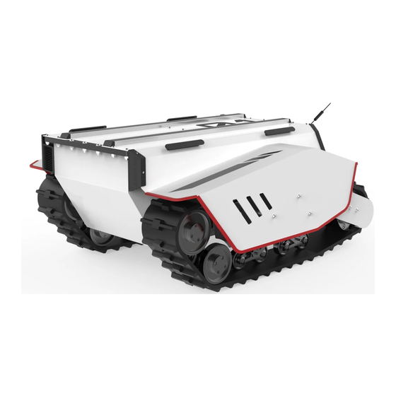
- Page 1 BUNKERpro AgileX Robotics Team V.1.0.0 2021.10 User Manual...
- Page 2 If you have any questions about use, please contact us at support@agilex.ai. Please followed and implement all assembly instructions and guidelines in the chapters of this manual, which is very important.
- Page 3 The integrators and end customers of BUNKERPRO have the responsibility to ensure compliance with relevant provisions and practical laws and regulations, and to ensure that there are no major hazards in the complete application of the robot.
-
Page 4: Table Of Contents
CONTENTS 1 Introduction to BUNKERPRO 3.4 Firmware upgrades 3.5 BUNKERPRO ROS Package 1.1 Product list use example 1.2 Performance parameters 1.3 Requirement for development 4 Precautions 4.1 Battery precautions 4.2 Precautions for operational 2 Basic Introduction environment 2.1 Instructions on electrical 4.3 Precautions for electrical... -
Page 5: Introduction To Bunkerpro
Communication interface 1.3 Requirement for development BUNKERPRO is equipped with FS remote control at the factory, and users can control the BUNKERPRO mobile robot chassis through remote control to complete the movement and rotation operations; BUNKERPRO is equipped with CAN interface, and users can carry out... -
Page 6: Instructions On Electrical Interfaces
2 The Basics This section will give a basic introduction to the BUNKERPRO mobile robot chassis, so that users and developers have a basic understanding of the BUNKERPRO chassis. 2.1Instructions on electrical interfaces The rear electrical interfaces are shown in Figure 2.1, where Q1 is the CAN and 48V power aviation interface,... -
Page 7: Instructions On Control Demands And Movements
Figure 2.4. Figure 2.4 Schematic Diagram of Reference Coordinate System for Vehicle Body As shown in Figure 2.4, the vehicle body of BUNKERPRO is parallel to the X axis of the established reference coordinate system. In the remote control mode, push the remote control joystick S1 forward to move in the positive direction of the X axis, and push S1 backward to move in the negative direction of the X axis. -
Page 8: Charging
3.2 Charging BUNKERPRO is equipped with a standard charger by default, which can meet the charging needs of customers. The specific operating procedures of charging are as follows: Make sure that the BUNKERPRO chassis is in a shutdown state. Before charging, please make sure that Q2 (power switch) in the rear electrical console is turned off;... - Page 9 Table 3.2 Description of Fault Information Description of Fault Information Byte Meaning bit [0] Battery undervoltage fault bit [1] Battery undervoltage warning Remote control disconnection protection (0: bit [2] normal, 1: remote control disconnection) No.1 motor communication failure (0: No bit [3] failure 1: Failure) No.2 motor communication failure (0: No...
- Page 10 Note [1] Description of control mode When the remote control of BUNKERPRO is not powered on, the control mode is standby mode by default, and you need to switch it to command mode to send movement control command. If the remote control is turned on, the remote control has the highest authority and can shield the control of commands.
- Page 12 Note 3: Sample data; the following data is for testing purposes only 1. The vehicle advances at a speed of 0.15/S byte [0] byte [1] byte [2] byte [3] byte [4] byte [5] byte [6] byte [7] 0x00 0x00 0x00 0x00 0x00 0x00...
- Page 13 Table 3.8 Motor Temperature, Voltage and Status Information Feedback Command Name Motor Drive Low Speed Information Feedback Frame Receive Sending Receiving Cycle(ms) node node time-out(ms) Steer-by- Decision- None None wire making control 0x261~0x264 chassis unit Data 0x08 length Description Position Function byte [0] Reserved...
- Page 14 Table 3.10 Odometer Feedback Frame Comman Odometer Information Feedback Frame d Name Receive time- Sending Receiving node Cycle(ms) node out(ms) Steer-by- Decision-making wire 0x311 20ms None control unit chassis Data 0x08 length Position Function Data type Description Highest bit of left byte [0] wheel odometer Second-highest bit...
-
Page 15: Can Cable Connection
3.3.2 CAN cable connection BUNKERPRO is shipped with a aviation plug male connector as shown in Figure 3.2. The definition of the cable: yellow is CANH, blue is CANL, red is power positive, and black is power negative. Note: In the current BUNKERPRO version, the external Red: VCC (battery positive) extension interface is only open to the rear interface. -
Page 16: Bunkerpro Ros Package
•AGILEX BUNKERPRO top aviation socket X1 Hardware connection and preparation •Lead out the CAN cable of the BUNKERPRO top aviation plug or the tail plug, and connect CAN_H and CAN_L in the CAN cable to the CAN_TO_USB adapter respectively; •Turn on the knob switch on the BUNKERPRO mobile robot chassis, and check whether the emergency stop switches on both sides are released;... -
Page 17: Precautions
5 Q&A Q:BUNKERPRO is started normally, but why does it not move when using the remote control to control the vehicle body? A:First, confirm whether the power switch is pressed; and then, confirm whether the control mode selected through the mode selection switch on the upper left side of the remote control is correct. -
Page 18: Product Dimensions
6 Product Dimensions 6.1 Illustration diagram of product dimensions 1064... -
Page 19: Illustration Diagram Of Top Extended Support Dimensions
6.2 Illustration diagram of top extended support dimensions... - Page 20 AgileX Robotics (Dongguan) CO., Ltd. WWW.AGILEX.AI TEL:+86-0769-22892150 MOBILE: +86-19925374409...
Need help?
Do you have a question about the BUNKERpro and is the answer not in the manual?
Questions and answers