Table of Contents
Advertisement
Quick Links
Advertisement
Table of Contents

Subscribe to Our Youtube Channel
Related Manuals for AgileX BUNKER PRO


Summary of Contents for AgileX BUNKER PRO
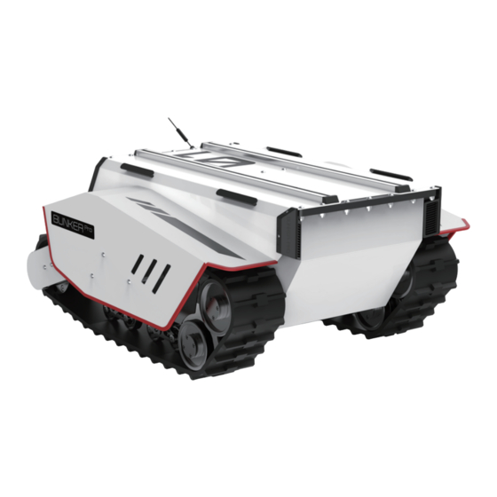
- Page 1 BUNKER PRO User Manual BUNKER PRO AgileX Robotics Team User Manual V.2.0.1 2023.09 Document version Edited Version Date Reviewer Notes V1.0.0 2023/3/17 谢瑞亲 first draft Add rendering image V2.0.0 2023/09/02 Modify how to use ROS package 谢 亲 Document checking 1 / 3 5...
- Page 2 If you have any questions about use, please contact us at support@agilex.ai . Please followed and implement all assembly instructions and guidelines in the chapters of this manual, which is very important.
- Page 3 ● This robot does not have the relevant safety functions of acomplete autonomous mobile robot, including but notlimited to automatic anti-collision, anti-falling, creature approach warning, etc. Relevant functions require integrators and end customers to conduct safety assessment in accordance with relevant provisions and applicable laws and regulations to ensure that the developed robot is free of any major hazards and hidden dangers in practical application.
- Page 4 ● Please use it in an environment that meets the requirements of the protection level according to the IP protection level of the equipment. ● Do not push the vehicle directly. ● When charging, make sure that the ambient temperature is greater than 0°C. Maintenance ●...
- Page 5 Do not store it around heating elements such as heaters or large coiled resistors; ● Except for the specially customized version (customized with IP protection level), BUNKER PRO is not waterproof, so please do not use it in environments with rain, snow, or standing water;...
-
Page 6: Table Of Contents
CONTENTS Document version Important Safety Information Attention CONTENTS 1 Introduction to BUNKERPRO 1.1 Product list 1.2 Tech specifications 1.3 Requirement for development 2 The Basics 2.1Instructions on electrical interfaces 2.2 Instructions on remote control 2.3 Instructions on control demands and movements 3 Use and Development 3.1 Use and operation 3.2 Charging 3.3.2 CAN cable connection 3.3.3 Realization of CAN command control 3.4 Firmware upgrade... -
Page 7: Introduction To Bunkerpro
EOD, special shooting, special transportation, etc., to solve robot movement solutions. 1.1 Product list Name Quantity BUNKER PRO Robot Body Battery Charger(AC 220V) Aviation male plug (4-Pin) FS remote control transmitter(Optional) USB to CAN communication module 1.2 Tech specifications... - Page 8 Front/rear wheel base (mm) Chassis height Track width Curb weight (kg) Battery Type Lithium battery Battery parameters 60AH Power drive motor 2×1500W Brushless servo motor Steering drive motor Parking mode Steering Track type differential steering Christie suspension + Matilda four- Suspension form wheel balance suspension Steering motor reduction...
-
Page 9: Requirement For Development
Ground clearance (mm) Maximum battery life (h) Maximum distance (km) 15KM Charging time (h) Working temperature (℃) -10~60℃ Remote control Control Control mode Command control mode Control RC transmitter 2.4G/extreme distance 200M System interface 1.3 Requirement for development BUNKERPRO is equipped with FS remote control at the factory, and users can control the BUNKERPRO mobile robot chassis through remote control to complete the movement and rotation operations;... - Page 10 The rear electrical interfaces are shown in Figure 2.1, where Q1 is the CAN and 48V power aviation interface, Q2 is the power switch, Q3 is the charging interface, Q4 is the antenna, Q5 and Q6 are respectively the driver debugging interface and the main control debugging interface (not open to the outside), and Q7 is the power display interaction.
-
Page 11: Instructions On Remote Control
Fs remote control is an optional accessory for BUNKER PRO products. Customers can choose according to actual needs. Using the remote control can easily control the BUNKER PRO universal robot chassis. In this product, we use the left-hand throttle design. Its definition and functions can be referred to Figure 2.3. - Page 12 Figure 2.3 Schematic diagram of the FS remote control buttons Remote control interface description: Bunker : model Vol: battery voltage Car: chassis status Batt: Chassis power percentage P: Park Remoter: remote control battery level Fault Code: Error information (Represents byte [5] in 211 frame) 1 2 / 3 5...
-
Page 13: Instructions On Control Demands And Movements
2.3 Instructions on control demands and movements We set up a coordinate reference system for ground mobile vehicle according to the ISO 8855 standard as shown in Figure 2.4. Figure 2.4 Schematic Diagram of Reference Coordinate System for Vehicle Body As shown in Figure 2.4, the vehicle body of BUNKERPRO is parallel to the X axis of the established reference coordinate system. -
Page 14: Use And Operation
Basic operating procedures of remote control ● After starting the BUNKERPRO robot chassis normally, start the remote control and select the remote control mode to control the movement of the BUNKER PRO platform through the remote control. 3.2 Charging BUNKERPRO is equipped with a standard charger by default, which can meet the charging needs of customers. - Page 15 BUNKERPRO provides a CAN interface for the user's development, and the user can control the vehicle body through this interface. The CAN communication standard in BUNKERPRO adopts the CAN2.0B standard; the communication baud rate is 500K, and the message format adopts the MOTOROLA format. The linear velocity of the movement and the angular velocity of the rotation of the chassis can be controlled through the external CAN bus interface;...
- Page 16 0x00 Standby mode byte [1] Mode control unsigned int8 0x01 CAN command control mode 0x03 Remote control mode The battery voltage is byte [2] 8 bits higher Actual voltage × 10 (with an unsigned int16 accuracy of 0.1V) The battery voltage is byte [3] eight bits lower...
- Page 17 bit [5] Reserved, default 0 bit [6] Reserved, default 0 bit [7] Reserved, default 0 The command of movement control feedback frame includes the feedback of current linear velocity and angular velocity of moving vehicle body. The specific protocol content is shown in Table 3.3.
- Page 18 byte [6] Reserved 0x00 byte [7] Reserved 0x00 The control frame includes linear velocity control opening, angular velocity control opening and check sum. The specific content of the protocol is shown in Table 3.4. Table 3.4 Movement Control Frame Command Name Control Instruction Receive timeout Sending node...
- Page 19 The mode setting frame is used to set the control interface of the terminal. The specific protocol content is shown in Table 3.5 Table 3.5 Control Mode Setting Frame Command Name Control Mode Setting Command Receive timeout Sending node Receiving node Cycle (ms) (ms) Decision-making...
- Page 20 Data length 0x01 Function Data type Description Position 0x00 clear all errors Error clearing byte [0] unsigned int8 0x01 Clear motor 1 s error ’ command 0x02 Clear motor 2 s error ’ Note 3: Sample data; the following data is for testing purposes only 1.
- Page 21 Position Function Data type Description 8-bit high motor byte [0] speed Current motor speed signed int16 Unit RPM 8-bit low motor byte [1] speed byte [2] Reserved 0x00 8-bit low drive byte [3] Unit 1℃ temperature byte [4] Reserved 0x00 byte [5] Drive status unsigned int8...
- Page 22 8-bit high drive byte [2] temperature signed int16 Unit 1℃ 8-bit low drive byte [3] temperature byte [4] Reserved 0x00 byte [5] Drive status unsigned int8 See Table 3.9 for details byte [6] Reserved 0x00 byte [7] Reserved 0x00 Table 3.9 Drive Status Byte Description Whether the power supply voltage is too low (0:Normal...
- Page 23 Receive timeout Sending node Receiving node Cycle (ms) (ms) Decision- Steer-by- wire making 0x311 20ms None chassis control unit Data length 0x08 Position Function Data type Description Highest bit of byte [0] left wheel odometer Second-highest byte [1] bit of left wheel Chassis left wheel odometer odometer feedback...
- Page 24 Lowest bit of byte [7] right wheel odometer Table 3.11 Remote Control Information Feedback Command Name Remote Control Information Feedback Frame Receive timeout Sending node Receiving node Cycle (ms) (ms) Decision- Steer-by- wire making 0x241 20ms None chassis control unit Data length 0x08 Position...
-
Page 25: Can Cable Connection
Left lever left byte [4] signed int8 Range: [-100,100] right byte [5] Left knob VRA signed int8 Range: [-100,100] byte [6] Reserved 0x00 byte [7] Count check unsigned int8 0-255 cycle count 3.3.2 CAN cable connection BUNKERPRO is shipped with a aviation plug male connector as shown in Figure 3.2. The definition of the cable: yellow is CANH, blue is CANL, red is power positive, and black is power negative. -
Page 26: Firmware Upgrade
firmware upgrade and the corresponding client software. Upgrade Preparation ● Agilex CAN debugging module X 1 ● Micro USB cable X 1 BUNKER PRO chassis X 1 ● ● A computer (WINDOWS OS (Operating System)) X 1 Upgrade Process 1.Plug in the USBTOCAN module on the computer, and then open the AgxCandoUpgradeToolV1.3_boxed.exe software (the sequence cannot be wrong, first open the... - Page 27 3.Click the Load Firmware File button to load the firmware to be upgraded. If the loading is successful, the firmware information will be obtained, as shown in the figure 2 7 / 3 5...
- Page 28 4.Click the node to be upgraded in the node list box, and then click Start Upgrade Firmware to start upgrading the firmware. After the upgrade is successful, a pop-up box will prompt. 2 8 / 3 5...
-
Page 29: Bunkerpro Ros Package Use Example
Hardware preparation ● CANlight can communication module X1 ● Thinkpad E470 notebook X1 ● AGILEX BUNKERPRO mobile robot chassis X1 ● AGILEX BUNKERPRO supporting remote control FS-i6s X1 ● AGILEX BUNKERPRO top aviation socket X1 Use example environment description ● Ubuntu 18.04 ● ●... - Page 30 ROS installation and environment setting For installation details, please refer to http://wiki.ros.org/kinetic/Installation/Ubuntu Test CANABLE hardware and CAN communication Setting CAN-TO-USB adaptor ● Enable gs_usb kernel module 复 代 sudo modprobe gs_usb ● Setting 500k Baud rate and enable can-to-usb adaptor 复 代 sudo ip link set can0 up type can bitrate 500000 ●...
- Page 31 ● Please refer to: https://github.com/agilexrobotics/agx_sdk https://wiki.rdu.im/_pages/Notes/Embedded-System/-Linux/can-bus-in-linux.html AGILEX BUNKERPRO ROS PACKAGE download and compile ● Download ros dependent package 复 代 $ sudo apt install -y ros-$ROS_DISTRO-teleop-twist-keyboard ● Clone and compile bunker_ros source code 复 代 mkdir -p ~/catkin_ws/src cd ~/catkin_ws/src git clone https://github.com/agilexrobotics/ugv_sdk.git git clone https://github.com/agilexrobotics/bunker_ros.git cd ..
- Page 32 Github ROS development package directory and usage instructions *_base:: The core node for the chassis to send and receive hierarchical CAN messages. Based on the communication mechanism of ros, it can control the movement of the chassis and read the status of the bunker through the topic.
-
Page 33: Product Dimensions
5 Product Dimensions 5.1 Illustration diagram of product dimensions 3 3 / 3 5... - Page 34 5.2 Illustration diagram of top extended support dimensions 3 4 / 3 5...
- Page 35 3 5 / 3 5...
Need help?
Do you have a question about the BUNKER PRO and is the answer not in the manual?
Questions and answers