
Subscribe to Our Youtube Channel
Related Manuals for AgileX RANGER MINI 2.0


Summary of Contents for AgileX RANGER MINI 2.0
- Page 1 RANGER MINI 2.0 User Manual RANGER MINI 2.0 AgileX Robotics Team USER MANUAL V.2.0.1 2023.08 Document version Version Date Edited by Reviewer Notes V1.0.0 2023/2/6 何士玉 First draft 1 / 5 2...
- Page 2 Added odometer data ● feedback Added remote control ● data feedback V1.0.1 2023/3/1 何士玉 Changed firmware ● upgrade method and instructions Optimize layout ● ● Add battery precautions ● Added usage V1.0.2 2023/3/21 environment ⼠ precautions ● Add safety precautions ●...
- Page 3 Before using the robot, any individual or organization must read and understand the manual. If you have any questions about it, please do not hesitate to contact us at support@agilex.ai . It is very important that you should follow and implement all instructions and guidelines in this manual.
- Page 4 For the first use, please read this manual carefully to understand the basic operation and operating specifications. ● Remote control operation should be in a relatively open area. The RANGER MINI 2.0 does not have any automatic obstacle avoidance sensors. ●...
- Page 5 ● Please do remote control within sight. ● The maximum load of the RANGER MINI 2.0 is 80 KG. Please ensure that the payload does not exceed 80 KG when using. ● When installing external equipment on the RANGER MINI 2.0, Please ensure their centroid location is at the RANGER MINI 2.0...
- Page 6 ● The operating temperature of RANGER MINI is -10°C~40°C, please do not use it in an environment where the temperature is lower than -10°C and higher than 40°C ● Do not use it in an environment with corrosive or flammable gases or near flammable substances.
-
Page 7: Table Of Contents
1.3 Required for Development 2 Basic Introduction 2.1 Status of the RANGER MINI 2.0 2.2 Description of Electrical Interfaces 2.3 Remote Control Instructions 3 Usage and Development 3.1 Operation 3.2 CAN Communication Protocol 3.3 RANGER MINI 2.0 use manual for ROS 3.4 Firmware Upgrade 4 Product Size 1 Introduction to the RANGER MINI 2.0 7 / 5 2... -
Page 8: Product List
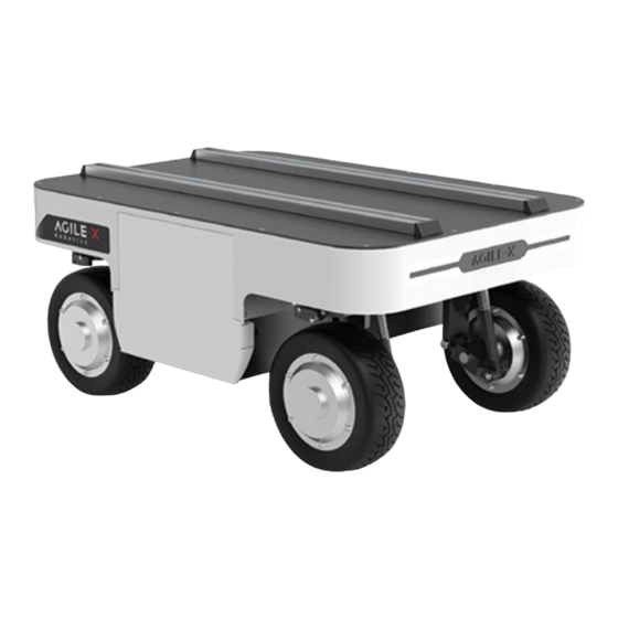
Compared with the four-wheel differential chassis, the RANGER MINI 2.0 has obvious advantages when running on ordinary cement roads and asphalt roads. It not only has higher speed and load capacity, but also reduces the wear and tear on the structure and tires. - Page 9 Kerb weight (Kg) 64.5 Battery type Lithium iron phosphate Battery parameters 48V24AH Power drive motor 350W×4 Steering drive motor 100W×4 Parking type Electronic brake Steering type 4 wheels steering Suspension Independent suspension Steering motor reduction ratio 1:50 Multiturn absolute encoder (9 Steering motor encoder bit) Drive motor reduction ratio...
-
Page 10: Required For Development
Communication Interface 1.3 Required for Development The RANGER MINI 2.0 can be equipped with FS remote control when buying. Users can use it to control the 4WD chassis, complete mode switching, movement and steering. The RANGER MINI 2.0 has a standard CAN (Controller Area Network) communication interface to facilitate secondary development. -
Page 11: Status Of The Ranger Mini
MINI 2.0 to be used in some harsh environments. A standard aluminum extension bracket is installed on the RANGER MINI 2.0, which is convenient for users to carry external equipment. 2.1 Status of the RANGER MINI 2.0 The user can check the status of the RANGER MINI 2.0 through its CAN message. Please refer to Table 2.1 for specific status. Status... -
Page 12: Description Of Electrical Interfaces
When the battery voltage is lower than the safe level, it will actively cut off the power supply. Therefore, users need to pay attention to the low voltage alarm of the RANGER MINI 2.0 before reaching the critical voltage. Do not forget to charge the RANGER MINI 2.0 after use. -
Page 13: Remote Control Instructions
Function and Pin Type Note Number Definition Positive terminal. The voltage range is 46~50 V Power supply The load current cannot exceed 15 A. Power supply Negative terminal CAN_H CAN Hi (High) CAN_L CAN Lo (Low) Figure 2.3 Pin descriptions of the circular connector 2.3 Remote Control Instructions 1 3 / 5 2... - Page 14 Figure 2.4 Introduction of the remote control As shown in the figure above, the functions of the buttons are defined as follows: SWB is the control mode selection lever, dialed to the top is the command control mode, dialed to the middle or down is the remote control mode;...
-
Page 15: Usage And Development
Moving SWD to the top is front and rear Ackerman mode (the left joystick controls the speed, ① and the right joystick controls the steering angle) + spin mode (the left joystick does not move, ② the right joystick controls the spin direction) Moving SWD to the bottom is the oblique motion mode: the left joystick controls the speed, and the right joystick controls the steering angle (the maximum angle is 90°, which makes the RANGER MINI 2.0MINI 2.0MINI 2.0move laterally);... -
Page 16: Operation
When using it for the first time, check whether the power switch(Q3) in the rear electrical panel is pressed, if pressed, please press it, and then release it. At this time, the power switch is released, and the RANGER MINI 2.0 is powered off. Power on and off... - Page 17 Battery replacement RANGERMINI is equipped with a 48v24ah battery. During operation, when the battery power is too low, we can open the battery panel on the right side to quickly replace the battery. 1 7 / 5 2...
- Page 18 Connection of the CAN Cable The 4WD chassis is shipped with an circular connector male head. The definition of its lines can refer to the figure below: Figure 3.1 Overview of the circular connector 1 8 / 5 2...
-
Page 19: Can Communication Protocol
Start the RANGER MINI 2.0normally, turn on the remote control, and then switch the SWB to the command control mode (move SWB to the top). At this time, the RANGER MINI 2.0 will accept commands from the CAN bus, and the host can also analyze the status of the RANGER MINI 2.0 using the feedbacked real-time data through the CAN bus. - Page 20 0x00 Standby mode 0x01 Command control mode byte [1] Control mode unsigned int8 0x03 Remote control mode High order byte [2] byte of battery voltage unsigned int16 Actual voltage X 10 (the unit is 0.1 V) Low order byte [3] byte of battery voltage unsigned int32 Refer to the error message table for...
- Page 21 Lowest order byte [7] byte of error message Table 1 Error message table Error message Byte Bit Meaning Right front steering servo bit [0] warning (0: unfaulty; 1: faulty) Right rear steering servo bit [1] warning (0: unfaulty; 1: faulty) Left rear steering servo bit [2] warning (0: unfaulty;...
- Page 22 Right rear steering zero bit [1] point calibration status (0: unfaulty; 1: faulty) Left rear steering zero bit [2] point calibration status (0: unfaulty; 1: faulty) Left front steering zero bit [3] point calibration status (0: unfaulty; 1: faulty) Steering calibration timeout bit [4] (0: unfaulty;...
- Page 23 No. 7 motor driver bit [4] communication status (0: unfaulty; 1: faulty) No. 8 motor driver bit [5] communication status (0: unfaulty; 1: faulty) Over temperature protection bit [6] status (0: normal; 1: triggered) Over current protection bit [7] status (0: normal; 1: triggered) byte [7] Battery undervoltage status bit [0]...
- Page 24 Reserved, the default value is bit [7] The motion control feedback frame includes the current linear speed and steering angle of the vehicle. The details of the protocol are as follows Command Motion Control Feedback Command Node for Receive timeout Node for sending Period receiving (ms)
- Page 25 High order byte of steering byte [6] angle Actual steering angle X 1000 (the signed int16 unit is 0.001 °) byte [7] Low order byte of steering angle The motion control frame includes the linear speed control command and the steering angle control command. The details of the protocol are as follows: Command ...
- Page 26 Left turn direction is positive angle As shown in Figure 3.2.1, when the RANGER MINI 2.0 is in front and rear Ackerman mode, the feedback steering angle is (α+β)/2, left steering is negative, and right steering is positive; the feedback speed is the average value of the four wheels speed (that is, the linear speed of the...
- Page 27 Figure 3.2.1 The Ackerman structure of the RANGER As shown in Figure 3.2.2, when the RANGER MINI 2.0 is in oblique motion mode, the feedback steering angle is (α1+α2+α3+α4)/4, left steering is negative, and right steering is positive; the feedback linear speed is the average value of the four wheels speed, reversing is negative, and ’...
- Page 28 Figure 3.2.2 Wheels control of the RANGER MINI 2.0 in oblique motion mode When the chassis is in the spin mode, the steering angle is a constant value , which cannot be changed. At this time, the feedback steering angle is the average value of the absolute values of α1, α2, α3, and α4.
- Page 29 Data length 0x01 Byte Meaning Data type Note 0x00 Standby mode byte [0] Control mode unsigned int8 0x01 CAN command control mode Boot into standby mode by default Control mode description: when the chassis is powered on and the remote control is not connected, the control mode is standby mode.
- Page 30 0x00 Clear all non-critical faults 0x01~0x08 Clear the communication faults of No. 1~8 motor drivers respectively 0x09 Clear the battery undervoltage fault and try to restore the power supply Error clearing byte [0] unsigned int8 command 0x0a Clear remote control signal loss fault 0x0b~0x0e Clear the steering calibration fault of No.
- Page 31 PS: The eight motor numbers of the chassis are: No. 1 is the right front wheel motor, No. 2 is the right rear wheel motor, No. 3 is the left rear wheel motor, No. 4 is the left front wheel motor, No. 5 is the right front steering motor, No. 6 is the right rear steering motor, No. 7 is the left rear steering motor, and No.
- Page 32 Highest order byte of position byte [4] High order byte [5] byte of position signed int32 The current position of the motor, byte [6] Low order whose unit is the number of pulses byte of position byte [7] Lowest order byte of position Feedback of temperature voltage and status of motor Command ...
- Page 33 The unit is 1 ℃. byte [4] Motor temperature signed int8 (Invalid value for RANGM series and can be ignored) byte [5] Driver status unsigned int8 See Table 2 for details byte [6] Reserved 0X00 byte [7] Reserved 0X00 Table 2 Driver status Byte Meaning bit[0]...
- Page 34 Drive-by-wire Decision-making 0x271 20ms None chassis and control unit Data length 0x08 Byte Meaning Data type Note High order byte of steering angle of No. byte [0] 5 motor The Current steering angle, signed int16 whose unit is 0.01 ° Low order byte [1] byte of steering angle of No. 5 motor High order byte of steering...
- Page 35 High order byte of steering angle of No. byte [6] 8 motor The Current steering angle, signed int16 whose unit is 0.01 ° Low order byte [7] byte of steering angle of No. 8 motor Rotational speed feedback of four wheels Command Information feedback frame of four wheels rotational speed ’...
- Page 36 High order byte of rotational speed of No. byte [2] 2 motor The current rotational speed, signed int16 whose unit is mm/s Low order byte [3] byte of rotational speed of No. 2 motor High order byte of rotational speed of No. byte [4] 3 motor The current rotational speed, signed int16 whose unit is mm/s Low order byte [5] byte of rotational...
- Page 37 Drive-by-wire Decision-making 0x291 20ms None chassis and control unit Data length 0x02 Byte Meaning Data type Note 0x00 front and rear Ackerman mode 0x01 oblique motion mode unsigned int8 Current motion byte [0] 0x02 spin mode mode 0x03 Parking mode 0x00 switching is completed. Whether the 0x01 in the process of chassis is in the...
- Page 38 Decision-making Node for the 0x141 None None and control unit chassis Data length 0x01 Byte Meaning Data type Note 0x00 front and rear Ackerman mode (default) 0x01 oblique motion mode byte [0] Motion mode unsigned int8 0x02 spin mode 0x03 Parking mode The odometer information feedback frame is as follows Front wheel Command Front wheel mileage feedback...
- Page 39 Highest order byt e of front left wheel odometer Sub- high order byte byte [0] of front left Chassis left wheel odometer byte [1] wheel odometer feedback, signed int32 Second byte [2] Unit: mm low order byte of byte [3] front left wheel odometer Lowest order byt e of front left wheel odometer Highest order byte of front...
- Page 40 Node for Receive timeout Node for sending Period receiving (ms) Drive-by-wire Decision-making 0×312 20ms None chassis and control unit Data length 0×08 Byte Description Data type Note Highest order byt e of rear left wheel odometer Sub- high order byte byte [0] of rear left wheel Chassis left wheel odometer byte [1] odometer...
- Page 41 Highest order byte of rear right wheel odometer Sub- high order byte byte [4] of rear right Chassis right wheel odometer byte [5] wheel odometer feedback, signed int32 byte [6] Second Unit: mm low order byte of byte [7] rear right wheel odometer Lowest order byt e of rear right wheel odometer The remote controller information feedback frame is as follows...
- Page 42 bit[0-1]: SWA:2- Up 3-Down bit[2-3]: SWB : 2-Up 1-Middle 3- Remote control Down byte [0] unsigned int8 SW feedback bit[4-5]: SWC : 2-Up 1-Middle 3- Down bit[6-7]: SWD 2-Up 3-Down Right joystick byte [1] unsigned int8 Range:[-100,100] left and right Right joystick up byte [2] unsigned int8...
- Page 43 Data length 0x08 Byte Meaning Data type Note Battery SOC byte [0] State of unsigned int8 Range 0~100 Charge Battery byte [1] SOH (State of unsigned int8 Range 0~100 Health) High order byte byte [2] of battery voltage unsigned int16 Unit: 0.01 V byte [3] Low order byte of battery voltage...
-
Page 44: Ranger Mini 2.0 Use Manual For Ros
Drive-by-wire Decision-making 0x362 500ms None chassis and control unit Data length 0x04 Byte Meaning Data type Note BIT1: Overvoltage; BIT2: Undervoltage; BIT3: High byte [0] Alarm Status 1 unsigned int8 temperature; BIT4: Low temperature; BIT7: Discharge overcurrent byte [1] Alarm Status 2 unsigned int8 BIT0: Charging overcurrent BIT1: Overvoltage;... - Page 45 ● Hardware Connection and Preparation Pull out the CAN wires of the circular connector on the rear of RANGER MINI 2.0, and connect can_H and can_L wires of the CAN to the CAN_TO_USB adapter; power on the RANGER MINI 2.0; connect the CAN_TO_USB adapter to the USB port of the laptop. The wiring diagram is shown in the figure below.
- Page 46 If the can-to-usb has been connected to the BUNKER robot this time, and the car has been turned on, use the following commands to monitor the data from the BUNKER chassis candump can0 Please refer to: https://github.com/agilexrobotics/agx_sdk https://wi-ki.rdu.im/_pages/Notes/Embedded-System/Linux/-can-bus-in-linux.html AGILEX RANGER ROS PACKAGE download and compile ● Download ros package sudo install libasio-dev 4 6 / 5 2...
- Page 47 sudo install ros-$ROS_DISTRO-teleop-twist-keyboard ● Clone compile hunter_ros code $ cd ~/catkin_ws/src clone --recursive https://github.com/agilexrobotics/ugv_sdk.git $ git clone https://github.com/agilexrobotics/ranger_ros.git $ cd .. $ catkin_make Please refer to https://github.com/agilexrobotics/ranger_ros Start the ROS node ● Start the based node roslaunch ranger_bringup ranger_minimal.launch Note that the usb_to_can module equipped with Songling needs to be enabled before starting. The enabling command is as follows: rosrun ranger_bringup bringup_can2usb.bash.
-
Page 48: Firmware Upgrade
In order to facilitate users to upgrade the firmware version used by RANGERMINI 2.0 and bring customers a more complete experience, RANGERMINI 2.0 provides a firmware upgrade hardware interface and corresponding client software. Upgrade Preparation ● Agilex CAN debugging module X 1 ● Micro USB cable X 1 ● RANGERMINI 2.0 chassis X 1 ●... - Page 49 3.Click the Load Firmware File button to load the firmware to be upgraded. If the loading is successful, the firmware information will be obtained, as shown in the figure 4 9 / 5 2...
- Page 50 4.Click the node to be upgraded in the node list box, and then click Start Upgrade Firmware to start upgrading the firmware. After the upgrade is successful, a pop-up box will prompt. 5 0 / 5 2...
-
Page 51: 4 Product Size
4 Product Size 5 1 / 5 2... - Page 52 5 2 / 5 2...
Need help?
Do you have a question about the RANGER MINI 2.0 and is the answer not in the manual?
Questions and answers