Table of Contents

Subscribe to Our Youtube Channel
Related Manuals for AgileX HUNTER SE


Summary of Contents for AgileX HUNTER SE
- Page 1 HUNTER SE USER MANUAL HUNTER SE AgileX Robotics Team USER MANUAL V.2.0.0 2023.09 Document version Version Date Edited by Reviewer Notes Update the ROS package usage section 2023/08/2 谢瑞亲 V.2.0.0 Add picture Format adjustment 1 / 4 0...
- Page 2 HUNTER SE integrators and end customers have the responsibility to ensure compliance with the applicable laws and regulations of relevant countries, and to ensure that there are no major dangers in the complete robot application.This includes but is not limited to the following:...
- Page 3 Itisstrictlyforbidden to carry people ● For remote control operation, select a relatively open area to use HUNTER SE, because it is not equipped with any automatic obstacle avoidance sensor.Please keep a safe distance of more than 2 meters when HUNTERSE is moving.
- Page 4 Battery ● The battery supplied with HUNTER SE is not fully charged in the factory setting, but its specific power capacity can be displayed on the voltmeter at rear end of HUNTER SE chassis or read via CAN bus communication interface. The battery recharging can be stopped when the green LED on the charger turns green.
- Page 5 Usage environment ● The operating temperature of HUNTER SE is -10℃to 45℃; please do not use it below -10℃ or above 45℃; ● The requirements for relative humidity in the operational environment of HUNTER SE are: maximum80%,minimum30%; ● Please do not use it in the environment with corrosive and flammable gases or closed to combustible substances;...
-
Page 6: Table Of Contents
Contents Document version Safety Information Attention Contents 1 HUNTER SE Introduction 1.1 Component list 1.3 Requirement for development 2 The Basics 2.1 Status indication 2.2 Instructions on electrical interfaces 2.2.1 Instructions on rear electrical interface 2.3 Instructions on remote control 2.4 Instructions on control demands and movements 3 Getting Started 3.1 Use and operation 3.2 Charging and battery replacement... -
Page 7: Hunter Se Introduction
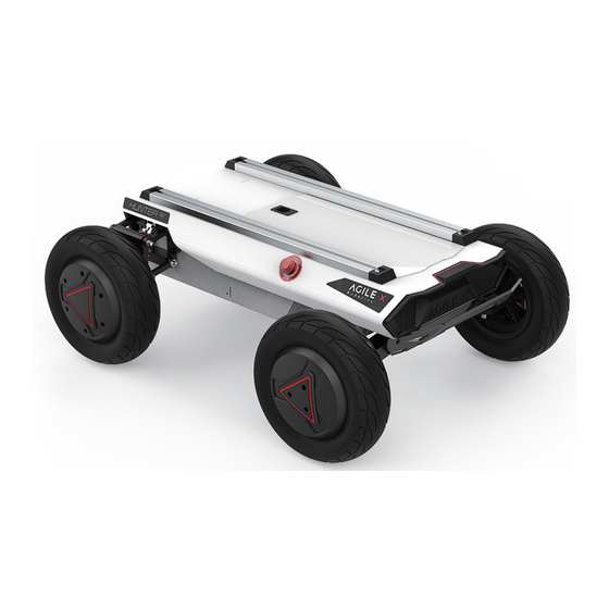
5.1 Illustration diagram of product external dimensions 5.2 Illustration diagram of top extended support dimensions 1 HUNTER SE Introduction HUNTERSE is an Ackermann model programmable UGV (UNMANNED GROUND VEHICLE), which is a chassis designed with Ackermann steering, with similar characteristics to cars, and has obvious advantages on ordinary cement and asphalt roads. - Page 8 Axle Track (mm) Front/rear track (mm) Kerb weight (Kg) Battery type Lithium battery Battery parameters 24V 30Ah/15Ah Power drive motor DC brushless 2 X 350W Steering drive motor DC brushless150W Loss of power Parking type electromagnetic brake Steering type Front wheel Ackermann Front wheel non-independent Suspension suspension + rear wheel...
-
Page 9: Requirement For Development
FS RC transmitter is provided (optional) in the factory setting of HUNTER SE, which allows users to control the chassis of robot to move and turn; HUNTER SE is equipped with CAN interface, and users can carry out secondary development through it. - Page 10 Figure2.1 FrontView Figure2.2 RearView 1 0 / 4 0...
-
Page 11: Status Indication
DC brush-less servo motor are used on the power module, which makes the HUNTER SE robot chassis development platform have a strong pass ability. And it is also easy for HUNTER SE to cross obstacles with the front wheel bridge suspension. Emergency stop switches... -
Page 12: Instructions On Rear Electrical Interface
2.2.1 Instructions on rear electrical interface The extension interface at the rear is shown in Figure 2.6, in which Q1 is the charging interface; Q2 is the power switch; Q3 is the power display interaction; Q4 is the CAN and 24V power extension interface. Thedefinition ofQ4 s specific pin isshown in Figure 2.7. - Page 13 FS remote control is an optional accessory for HUNTER SE. Customers can choose according to actual needs. The remote control can easily control the HUNTER SE universal robot chassis. In this product, we use the left-hand throttle design. Refer to Figure 2.8 for its definition and function.
-
Page 14: Instructions On Control Demands And Movements
Figure 2.8 Schematic diagram of the FS remote control buttons Remote control interface description: Hunter : model Vol: battery voltage Car: chassis status Batt: Chassis power percentage P:Park Remoter: remote control battery level Fault Code: Error information (refer to the fault information description table) 2.4 Instructions on control demands and movements We set up a coordinate reference system for ground mobile vehicle according to the ISO 8855 standard as shown in Figure 2.9. -
Page 15: Getting Started
3 Getting Started 3.1 Use and operation Thebasic operation process of thestartup operation is as follows: Check ● Check the condition of HUNTER SE. Check whether there are significant anomalies; if so, please contacttheafter-saleservicepersonalforsupport; ● Check the state of emergency-stop switches. Make suretheemergencystopbuttons arereleased; ●... -
Page 16: Charging And Battery Replacement
3.2 Charging and battery replacement HUNTER SE products are equipped with a 10A charger by default in the car, which can meet charging needs. During normal charging, there is no indicator light on the chassis to indicate the charging status of the vehicle. Please judge whether it is currently charging according to the charger status indicator light. - Page 17 Battery replacement ● Turn off the power switch of the HUNTER SE chassis ● Press the button lock on the battery replacement panel to open the battery panel ● Unplug the currently connected battery interface, respectively (XT60 power connector) (BMS connector) lock ●...
-
Page 18: Development
CAN bus interface; HUNTER SE will feedback the current movement status information and the status information of the HUNTER chassis in real time. The system status feedback command includes current vehicle body status feedback, control mode status feedback, battery voltage feedback and fault feedback.The protocol content is shown in Table 3.1. - Page 19 Steer-by-wire Decision-making 0x211 100ms None chassis control unit Data length 0x08 Position Function Datatype Description 0x00 Normal condition Current status of byte[0] vehicle unsignedint8 0x01 Emergency stop mode body 0x02 System exception 0x00 Standby mode byte[1] Modecontrol unsignedint8 0x01CAN command control mode 0x03 Remote control mode The battery voltageis 8...
- Page 20 DescriptionofFault byte Meaning bit[0] Reserved,default 0 bit[1] Reserved,default 0 bit[2] Remote control disconnection protection(0:No failure1 bit[3] Reserved,default 0 byte[4] bit[4] Upper layer communication connection(0:No failure 1: bit[5] Reserved,default 0 bit[6] Drive status error(0:No failure1:failure) bit[7] Reserved,default 0 bit[0] Battery under-voltage failure(0:No failure1:Failur bit[1] Steering zero setting error(0:No failure1:Failure) bit[2]...
- Page 21 Command Name Movement Control Feedback Frame Receivetime-out Sending node Receiving node Cycle ms (ms) Steer-by-wire Decision-making 0x221 20ms None chassis controluni Datalength 0x08 Position Function Datatype Description The movement speed is 8 bits byte[0] higher Actual speed × 1000 (with an signedint16 accuracy of 0.001m/s) The movement...
- Page 22 Command Motion Command Name Receivetime- Sending node Receiving node Cycle ms out(ms) Decision-mak Chassis node 0x111 20ms 500ms ingcontrol unit Datalength 0x08 Position Function Datatype Description The linear velocity is 8 bits higher byte[0] Moving speed of vehicle body, signed int16 unit:mm/s effective value: +-4800) byte[1] The linear...
- Page 23 CAN control mode. The mode setting frame is used to set the control interface of HUNTER SE. The specific protocol content is shown in Table 3.4.
- Page 24 Table 3.5 Status Setting Frame Command Name Status Setting Command Receivetime- Sending node Receiving node Cycle ms out(ms) Decision-making Chassis node 0x441 none none control unit Datalength 0x01 Position Function Datatype Description 0xFF Clear all non-critical failures 0x04 Clear the communication failure of the steering motor driver error clearing byte [0] unsigned int8...
- Page 25 The chassis status information will be feedback, and what s more, the information about motor ’ current, encoder and temperature are also included. The following feedback frame contains the information about motor current, encoder andmotor temperature. The corresponding motor numbers of the three motors in the chassis are: steering No. 1, right rear wheel No.
- Page 26 byte[4] byte[5] Reserved 0×00 byte[6] byte[7] Table 3.7 Motor Drive Low Speed Information FeedbackFrame Command Name Motor Drive Low Speed Information Feedback Frame Receivetime- Sending node Receivingnode Cycle ms out(ms) Steer-by-wire Decision-making 0x261~0x263 100ms None chassis control unit Datalength 0x08 Position Function Data type...
- Page 27 See the details in [Drive control byte[5] Drive status unsigned int8 status] byte[6] Reserved — 0x00 byte[7] Reserved — 0x00 The specific content of the drive status information is shown in Table 3.8. Table 3.8 Drive Status Description Drive Status Byte Description bit[0]...
- Page 28 Steer-by-wire Decision-making 0x432 None none chassis control unit Datalength 0x02 Position Function Datatype Description The zero offset byte[0] is 8 bits higher Zero offset value pulse numbe signedint16 reference value 22000+-10000 The zero offset byte[1] is 8 bits lower Table 3.11 Steering Zero Setting Feedback Command Command Name Steering Zero Setting Feedback Frame Receivetime-...
-
Page 29: Can Cable Connection
The query successfully returns offset value 0×43B 3.3.2 CAN cable connection HUNTER SE is shipped with a aviation plug male connector as shown in Figure 3.2. Refer to Table 3.2 for the definition of thecable. Figure 3.2 Schematic diagram of the male aviation plug 3.3.3 Implementation of CAN command control... - Page 30 To facilitate the customer's upgrading of the firmware version used by HUNTER SE and bring the customer a better experience, HUNTER SE provides a hardware interface for the firmware upgrading, and the corresponding client software as well. Upgrade Preparation ● Agilex CAN debugging module X 1 ●...
- Page 31 3.Click the Load Firmware File button to load the firmware to be upgraded. If the loading is successful, the firmware information will be obtained, as shown in the figure 4.Click the node to be upgraded in the node list box, and then click Start Upgrade Firmware to start upgrading the firmware.
-
Page 32: Hunterse Ros Package Use Example
3.5 HUNTERSE ROS Package use example 3 2 / 4 0... - Page 33 ● Hardware connection and preparation ● Lead out the CAN cable of the HUNTER SE tail plug, and connect CAN_H and CAN_L in the CAN cable to the CAN_TO_USB adapter respectively; ● Turn on the knob switch on the HUNTER SE mobile robot chassis, and check whether the emergency stop switches on both sides are released;...
- Page 34 ROS installation ● For installation details,please refer to http://wiki.ros.org/kinetic/Installa-tion/Ubuntu Test CANABLE hardware and CAN communication Setting CAN-TO-USB adaptor ● Enable gs_usb kernel module 复 代 sudo modprobe gs_usb ● Setting 500k Baud rate and enable can-to-usb adaptor 复 代 sudo link can0 type can bitrate 500000 ●...
- Page 35 https://wi-ki.rdu.im/_pages/Notes/Embedded-System/Linux/-can-bus-in-linux.html HUNTER SE ROS PACKAGE download and compile ● Download ros dependent package 复 代 sudo apt install -y ros-$ROS_DISTRO-teleop-twist-keyboard ● Clone and compile hunter_ros source code 复 代 $ cd ~/catkin_ws/src clone https://github.com/agilexrobotics/ugv_sdk.git $ git clone https://github.com/agilexrobotics/hunter_ros.git $ cd .. $ catkin_make ● Reference source: https://github.com/agilexrobotics/hunter_ros Start the ROS nodes ●...
-
Page 36: Product Dimensions
A:Normally, if HUNTER SE can be controlled by a RC transmitter, it means the chassis movement is under proper control; if the chassis feedback frame can be accepted, it means CAN extension link is in normal condition. Please check the CAN control frame sent to see whether the data check is correct and whether the control mode is in command control mode. - Page 37 5.1 Illustration diagram of product external dimensions 5.2 Illustration diagram of top extended support dimensions 3 7 / 4 0...
- Page 38 3 8 / 4 0...
- Page 39 3 9 / 4 0...
- Page 40 4 0 / 4 0...
Need help?
Do you have a question about the HUNTER SE and is the answer not in the manual?
Questions and answers