Table of Contents
Advertisement
Quick Links
Advertisement
Table of Contents

Related Manuals for AgileX HUNTER SE


Summary of Contents for AgileX HUNTER SE
-
Page 1: Agilex Robotics Team
HUNTER SE AgileX Robotics Team User Manual 2021.11.30... - Page 2 If you have any questions about use, please contact us at support@agilex.ai. Please follow and implement all assembly instructions and guidelines in the chapters of this manual, which is very important. Particular attention should be paid to the text related to the...
- Page 3 HUNTER SE integrators and end customers have the responsibility to ensure compliance with the applicable laws and regulations of relevant countries, and to ensure that there are no major dangers in the complete robot application.
- Page 4 damage. 5. Maintenance Regularly check the pressure of the tire, and keep the tire pressure at about 2.0 BAR. If the tire is severely worn or burst, please replace it in time. If the battery is not used for a long time, the battery needs to be charged periodically every 2 to 3 months.
-
Page 5: Table Of Contents
CONTEXT AgileX Robotics Team ....................1 1. HUNTER SE Introduction ....................6 1.1 Component list ......................6 1.2 Tech specifications ....................6 1.3 Requirement for development ................8 2. The Basics .......................... 8 2.1 Status indication ...................... 10 2.2 Instructions on electrical interfaces ............... 10 2.2.1 Instructions on rear electrical interface .............. -
Page 6: Hunter Se Introduction
1. HUNTER SE Introduction HUNTERSE is an Ackermann model programmable UGV (UNMANNED GROUND VEHICLE), which is a chassis designed with Ackermann steering, with similar characteristics to cars, and has obvious advantages on ordinary cement and asphalt roads. Compared with the four-wheel differential chassis, HUNTERSE has higher load capacity, can achieve higher movement speed, and at the same time wear less to the structure and tires, suitable for long-term work. - Page 7 speed (m/s) Minimum turning radius (m) 20° 120 (through angle 45°) Maximum climbing capacity Minimum ground clearance (mm) -10~45C° Operating temperature 50kg remote control Load Control parameters Control mode Remote control Command control mode RC transmitter 2.4G/extreme distance 200m Communication Interface...
-
Page 8: Requirement For Development
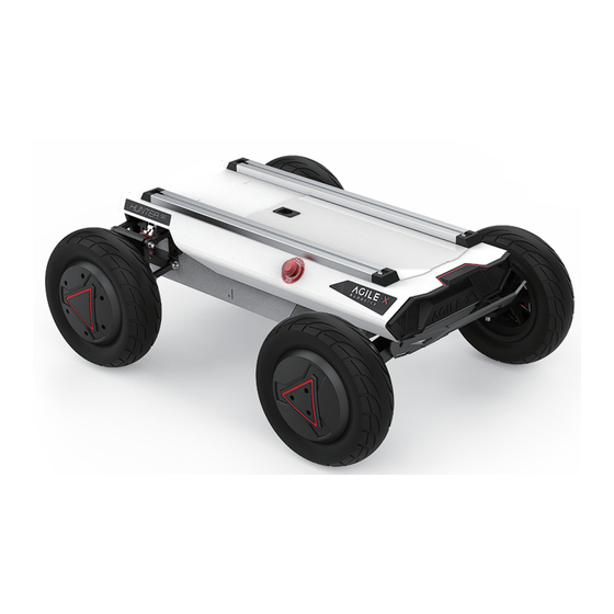
This section will give a basic introduction to the HUNTER SE mobile robot chassis, so that users and developers have a basic understanding of the HUNTER SE chassis. Figures 2.1 and 2.2 below provide the views of the entire mobile robot chassis. - Page 9 DC brush-less servo motor are used on the power module, which makes the HUNTER SE robot chassis development platform have a strong pass ability. And it is also easy for HUNTER SE to cross obstacles with the front wheel bridge suspension. Emergency stop switches are installed on both sides of the vehicle body, so that emergency stop operations can be performed quickly in the event of an emergency, so as to avoid safety accidents and reduce or avoid unnecessary losses.
-
Page 10: Status Indication
2.1 Status indication Users can identify the status of vehicle body through the voltmeter, the beeper and lights mounted on HUNTERSE. For details, please refer to Figure 2.1. Status Description Current voltage The current battery voltage can be viewed through the voltmeter in the rear electrical panel. -
Page 11: Instructions On Remote Control
SWD is the front light switch button; dial it to the top to turn on the light, and dial it to the bottom to turn off the light; S1 is the throttle button, which controls the HUNTER SE forward and backward; S2 controls the steering of the front wheel, while POWER is the power button, and you can turn on the remote control by pressing them at the same time. -
Page 12: Getting Started
3.2 Charging and battery replacement HUNTER SE is equipped with a 10A charger by default, which can meet the charging needs of customers. When charging normally, there is no description of the indicator light on the chassis. For specific instructions, please refer to the description of the charger indicator light. -
Page 13: Development
500K, and the message format adopts MOTOROLA format. The linear velocity and steering angle of the chassis movement can be controlled through the external CAN bus interface; HUNTER SE will feedback the current movement status information and the status information of the HUNTER chassis in real time. The system status feedback command includes current vehicle body status feedback, control mode status feedback, battery voltage feedback and fault feedback. - Page 14 Description of Fault byte Meaning byte [4] bit [0] Reserved, default 0 bit [1] Reserved, default 0 bit [2] Remote control disconnection protection (0: No failure 1: Failure) bit [3] Reserved, default 0 bit [4] Upper layer communication connection (0: No failure 1: Failure ) bit [5] Reserved, default 0 bit [6]...
- Page 15 PS: In the CAN command mode, it is necessary to ensure that the 0X111 command frame is sent in a period less than 500MS (recommended period is 20MS), otherwise HUNTER SE will judge that the control signal is lost and...
- Page 16 CAN control mode. The mode setting frame is used to set the control interface of HUNTER SE. The specific protocol content is shown in Table 3.4.
- Page 17 byte [0] error clearing command unsigned 0xFF Clear all non-critical failures 0x04 Clear the communication failure of the steering motor driver int8 0x05 Clear the communication failure of the rear right motor driver 0x06 Clear the communication failure of the rear left motor driver [Note] Sample data, the following data is only for testing 1.
- Page 18 is 8 bits lower byte [2] The motor byte [3] current is 8 bits signed int16 Motor current Unit 0.1A higher The motor current is 8 bits lower byte [4] byte [5] byte [6] byte [7] Reserved 0×00 Table 3.7 Motor Drive Low Speed Information Feedback Frame Command Name otor Drive Low Speed Information Feedback Frame Sending Receiving node...
- Page 19 Table 3.8 Drive Status Description Drive Status Byte Description bit [0] Whether the power supply voltage is too low (0: Normal 1: Too low) bit [1] Whether the motor is overheated (0: Normal 1: Overheated) bit [2] Whether the drive is over current (0: Normal 1: Over current) bit [3] Whether the drive is overheated (0: Normal 1: Overheated) bit [4]...
-
Page 20: 2Can Cable Connection
The query successfully returns 0×43B 3.3.2CAN cable connection HUNTER SE is shipped with a aviation plug male connector as shown in Figure 3.2. Refer to Table 3.2 for the definition of the cable. Red: VCC (battery positive) Black: GND (battery negative) - Page 21 Hardware connection and preparation Lead out the CAN cable of the HUNTER SE tail plug, and connect CAN_H and CAN_L in the CAN cable to the CAN_TO_USB adapter respectively; Turn on the knob switch on the HUNTER SE mobile robot chassis, and check whether the emergency stop switches on both sides are released;...
- Page 22 $ catkin_make If the can-to-usb has been connected to the Reference source: HUNTER SE robot this time, and the vehicle has https://github.com/agilexrobotics/hunter_ros been turned on, use the following commands to monitor the data from the HUNTER SE chassis Start the ROS nodes $ candump can0 ...
-
Page 23: Precautions
3. Precautions This section includes some precautions that should be paid attention to for HUNTER SE use and development. Battery The battery supplied with HUNTER SE is not fully combustible substances; charged in the factory setting, but its specific power... -
Page 24: Q&A
A: Normally, if HUNTER SE can be controlled by a RC transmitter, it means the chassis movement is under proper control; if the chassis feedback frame can be received, it means CAN extension link is in normal condition. Please check the CAN control frame sent to see whether the data check is correct and whether the control mode is in command control mode. -
Page 25: Product Dimensions
5. Product Dimensions 6.1 Illustration diagram of product external dimensions... - Page 26 6.2 Illustration diagram of top extended support dimensions Model:ZEN-OB1640Q Weight per meter:0.78kg/m Wall thickness:2mm...
- Page 27 AgileX Robotics (Dongguan) CO., Ltd. WWW.AGILEX.AI TEL:+86-769-22892150 MOBILE:+ 86-19925374409...
Need help?
Do you have a question about the HUNTER SE and is the answer not in the manual?
Questions and answers