Table of Contents
Advertisement
Quick Links
Advertisement
Table of Contents

Related Manuals for Veratron VMH 35-D


Summary of Contents for Veratron VMH 35-D
- Page 1 VMH 35-D MARINE DISPLAY USER MANUAL rev. AA VMH 35-D...
-
Page 2: Table Of Contents
Operate the Settings Menu ........15 Supported NMEA 2000 Messages ..... 29 Display Menu Structure ..........16 Disposal Responsibility ..........29 Change the Brightness of the Display ....16 SPARE PARTS AND ACCESSORIES ....30 Set the Day/Night Mode ..........16 VMH 35-D... -
Page 3: Introduction
The VMH 35-D is the perfect standalone solution for monitoring your diesel engine. With a configurable dial scale of 3000 or 4000 RPM, the VMH 35-D is a compact display capable of showing a wide amount of data from your engine, battery, tank, and GPS. -
Page 4: Safety Information
• Use our product only as intended. Use of the • Modifications or manipulations to Veratron product for reasons other than its intended products can affect safety. Consequently, you use may lead to personal injury, property may not modify or manipulate the product! •... -
Page 5: Safety After Installation
Adjust the stripper so that stranded wires are stabilized and it must comply with the not damaged or separated. • Use only a soft soldering process or following standard: DIN EN 61000, Parts 6-1 to 6-4. commercially available crimp connector to solder new cable connections! VMH 35-D... -
Page 6: Installation
If necessary, remove the main power switch. 2. Disconnect the negative terminal of the battery. Do not allow the battery to be reconnected by mistake. 3. When mounting the device in the vicinity of a magnetic compass, maintain a protective distance from the compass. VMH 35-D... -
Page 7: Spinlock Mounting
2. Remove the spinlock and insert the device from the front. 3. Orient the spinlock as shown according to the panel thickness. 4. Feed the cables through the spinlock and carefully screw it in for at least two turns. 5. Install the connector. VMH 35-D... -
Page 8: Electrical Connections
VMH 35 rear view Yellow EasyLink – Data Molex MX150 12-poles connector NMEA 2000® CONNECTOR PINOUT Pin No. Description Shield NET-S (V+) NET-C (V-) NET-H (CAN High) NET-L (CAN Low) Micro-C M12 5 poles plug male, cable view VMH 35-D... -
Page 9: Electrical Schematic
The display supports the connection of an external buzzer (B1) via the dedicated alarm output. This buzzer can be powered at different voltages (consult the buzzer manufacturer's manual) as the output steers the alarms ground connection (Open Collector Output). It is important to note that the maximum current supported is 500mA. VMH 35-D... -
Page 10: Day / Night Mode Switch (S1)
Be sure to tighten the M12 connector by screwing it onto its counterpart in order to preserve its watertightness. An accessory drop cable is required. (Not included) Note that NMEA 2000® does not allow drop cables longer than 6 meters. Refer to the NMEA 2000® standard for proper network design. VMH 35-D... -
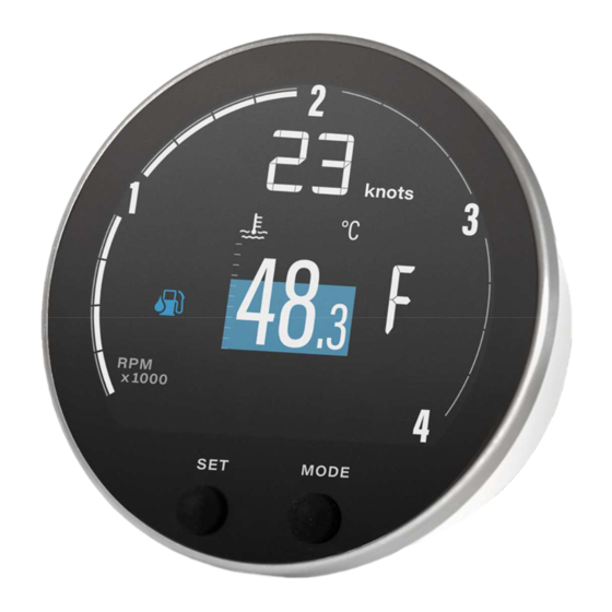
Page 11: Description
The coloured graphic in the background of the single layout screen is a bar diagram that puts the measured value in perspective. This function isn’t supported for all data types. The white lines on the left side show the scalation. VMH 35-D... -
Page 12: Basic Actions
Fuel flow L/h , gph FRESH Fresh water % , L , Gal WASTE Wastewater % , L , Gal Voltmeter Ammeter State of Charge Battery autonomy d , h Battery Status of health Battery temperature °C , °F VMH 35-D... -
Page 13: Distance Traveled
Speed through water km/h ,mph , (STW) km/h ,mph, GPS speed (SOG) Note*: data received from integrated GPS module. DISTANCE TRAVELED The indicator internally calculates the distance travelled based on the speed value set in Sensors > Speed. VMH 35-D... -
Page 14: Engine Hours
Is one information received from several sources, the priority is judged as stated below: In general 1. Analog Inputs 2. SAE J1939 3. NMEA 2000 Fuel data 1. Analog Inputs 2. NMEA 2000 3. J1939 GPS-Position 1. NMEA 2000 2. Internal GPS VMH 35-D... -
Page 15: General Settings
Press the MODE button until the previous data appears. exit the settings menu press the SET and MODE buttons until the pop-up disappears, or the previous data page appears close an alarm pop-up press any button VMH 35-D... -
Page 16: Display Menu Structure
SET THE DAY/NIGHT MODE To set the desired mode, connect pin 10 of the MX150 plug to the following potential: To set the mode... Then... move the pin switch to GND/OPEN. night move the pin switch to 12V/24V. VMH 35-D... -
Page 17: Units
You can choose which pages to hide/show in the menu under Display > Screens. If you are working with the Veratron Diagnostic Tool, you can make the selection of shown and hidden screens faster by making this setting in the Configuration Tool. -
Page 18: Setup Menu
Select which instance of engine information from the SAE J1939 network should be displayed on the VMH 35 screen in the menu Setup > J1939 Src. For simple CAN bus networks with only one engine this can be left at the default value “Auto”. VMH 35-D... -
Page 19: Adjust The Rpm Scale
A custom splash logo can be loaded from a PC using the Veratron Configuration Tool. This logo will then be displayed each time during the startup sequence of the device. For more information, please refer to the Veratron Configuration Tool user manual or contact your Veratron reseller. -
Page 20: Sensor Configuration
TYPES OF CALIBRATION Calibration of analog sensors can be: • Standard: only for Veratron sensors. You define the type of sensor, and the device reads with good approximation the value of the sensor without the need of calibration. • Manual: For non-Veratron sensors or to obtain a more accurate indication from a Veratron sensor. A three- or five-point procedure instructs the system to detect the sensor value. -
Page 21: Calibrate The Sensors
If you have chosen the CUSTOM configuration, follow the wizard on the display to create the sensor curve. (You will have to bring the rudder to a certain position and then confirm the current sensor value and repeat that for several points of the curve) VMH 35-D... -
Page 22: Selecting A Source For Voltage Data
Choose the desired configuration for the connected sensor type. • If you chose the CUSTOM configuration, create the sensor curve using the Veratron Configuration Tool. SELECTING A SOURCE FOR VOLTAGE DATA The information battery voltage can be received from the different sources NMEA 2000, J1939 and the display-internal voltage measurement. -
Page 23: Sensor Curves
Here are the possible alternatives: Selectable value Curve Single 10-180 Ω Dual 5-90 Ω CUSTOM Three-step calibration wizard COOLANT TEMPERATURE SENSORS Here are the possible alternatives: Selectable value Curve 120° 291-22 Ω CUSTOM Calibration via Veratron Configuration Tool VMH 35-D... - Page 24 SENSOR CURVES OIL TEMPERATURE SENSORS Here are the possible alternatives: Selectable value Curve 150° 197-11 Ω CUSTOM Calibration via Veratron Configuration Tool ENGINE OIL PRESSURE SENSORS Here are the possible alternatives: Selectable value Curve 5 bar 10-184 Ω 10 bar 10-184 Ω...
-
Page 25: Alarms
If supported, the alarm is forwarded over the NMEA 2000 network. ALARMS MENU STRUCTURE SET AN ALARM • In ALARMS > Setup select the value to activate the alarm and then Active. • Set the desired alarm threshold. VMH 35-D... -
Page 26: List Of Managed Alarms
Engine overspeed ALARM TELLTALES Icon Information Icon Information Fuel level Battery voltage Water in Fuel Engine failure AdBlue Level Engine coolant pressure GPS* Oil pressure Engine coolant temperature * blinking: no connection possible / constantly on: connection established VMH 35-D... -
Page 27: Troubleshooting
Slow update rate on The value is expected to be Disable the analog inputs when they are not being NMEA data received from the analog used. input. VMH 35-D... -
Page 28: Technical Data
ENVIRONMENTAL FEATURES Operating temperature From -20 to +60 °C Storage temperature From -30 to +80 °C ELECTRICAL FEATURES Nominal voltage 12 V / 24 V Operating voltage 9–32 V Current consumption < 170 mA @ 12 V Absorption (LEN) VMH 35-D... -
Page 29: Compliance
Local Time Offset 129033 Vessel heading 127250 Datum 129044 DISPOSAL RESPONSIBILITY Dispose of by separate collection through government or local government designated collection facilities. Proper disposal and recycling will help prevent potentially negative consequences for the environment and people. VMH 35-D... -
Page 30: Spare Parts And Accessories
SPARE PARTS AND ACCESSORIES SPARE PARTS AND ACCESSORIES Product Part Number Pigtail cable with MX150 connector A2C14333300 Spin lock A2C13760900 EasyLink extension cable A2C59500139 Rubber gasket A2C14624100 For all available accessories, visit http://www.veratron.com. VMH 35-D... - Page 31 - Print the document in its original format, in whole or in part. - Copy of contents without modification and declaration of Veratron AG as copyright owner. Veratron AG reserves the right to make changes or improvements to this documentation without notice. Requests for permission, additional copies of this manual, or technical information about this manual should be directed to Veratron AG.
Need help?
Do you have a question about the VMH 35-D and is the answer not in the manual?
Questions and answers