Table of Contents
Advertisement
Available languages
Available languages
Quick Links
Advertisement
Chapters
Table of Contents

Subscribe to Our Youtube Channel
Related Manuals for Veratron VMH 70


Summary of Contents for Veratron VMH 70
- Page 1 VMH 70 MARINE DISPLAY USER MANUAL rev. AA B001517...
- Page 2 LANGUAGE PAGE ENGLISH DEUTSCH ITALIANO B001517...
- Page 3 VMH 70 MARINE DISPLAY USER MANUAL rev. AA B001517...
-
Page 4: Table Of Contents
TABLE OF CONTENTS TABLE OF CONTENTS INTRODUCTION ............ 3 Engine Hours ..............22 Architecture ............... 3 Distance Traveled ............22 NavDash Layout ............23 SAFETY INFORMATION ........4 Safety during Installation ..........4 SCREENS CONFIGURATION ......24 Safety after Installation ..........5 SYSTEM CONFIGURATION ...... -
Page 5: Introduction
NMEA 2000 connectivity lets you view navigation data from other devices on the network, such as wind, compass, GPS, speed, and depth data. ARCHITECTURE Following is an example of an application with a VMH 70 display, used as a gateway and as a NMEA 2000 monitor. B001517... -
Page 6: Safety Information
• Use our product only as intended. Use of the • Modifications or manipulations to Veratron product for reasons other than its intended use products can affect safety. Consequently, you may lead to personal injury, property damage may not modify or manipulate the product! •... -
Page 7: Safety After Installation
SAFETY INFORMATION • Drill small ports; enlarge and complete them, if • The electrical indicator outputs and cables necessary, using taper milling tools, saber saws, connected to them must be protected from keyhole saws or files. Deburr edges. Follow the direct contact and damage. -
Page 8: Installation
INSTALLATION INSTALLATION WARNING Before starting work, disconnect the negative terminal of the battery to avoid the risk of a short circuit. If the vehicle is equipped with additional batteries, the negative terminal of all batteries must also be disconnected if necessary. Short circuits can burn cables, explode batteries and cause damage to other electronic systems. -
Page 9: Panel Mounting
INSTALLATION PANEL MOUNTING WARNING • Do not drill holes or installation openings in supporting or stabilizing beams! • The mounting location must have sufficient clearance behind the mounting holes or openings. 1. Make a rectangular hole in the panel using the drilling template (see next page of this document) and considering the device dimensions [A]. - Page 10 INSTALLATION B001517...
-
Page 11: Electrical Connections
ELECTRICAL CONNECTIONS ELECTRICAL CONNECTIONS WARNING • Refer to the safety rules described in the electrical connections section of the safety information chapter of this document! ENGINE 1 CONNECTOR [A] Pin No. Wire color Description KL. 30 – Battery power 12 / 24 V Black KL. -
Page 12: Engine 2 Connector [B]
ELECTRICAL CONNECTIONS ENGINE 2 CONNECTOR [B] Pin No. Wire color Description Pink Configurable alarm input Black KL. 31 - Ground White Alarm output Green Frequency sensor signal - RPM Blue SAE J1939 – CAN High Blue / White SAE J1939 – CAN Low Yellow 0-5 V sensor input Grey... -
Page 13: Nmea 2000® Connector [D]
ELECTRICAL CONNECTIONS NMEA 2000® CONNECTOR [D] Pin No. Description Shield NET-S (V+) NET-C (V-) NET-H (CAN High) Micro-C M12 5 poles plug NET-L (CAN Low) male, cable view Once the installation is complete, you can interface the device to the NMEA 2000®... -
Page 14: Electrical Schematic
ELECTRICAL CONNECTIONS ELECTRICAL SCHEMATIC Designations in the circuit diagram Batt - Term.30 – Battery Power 12/24 V S1 - Day/Night mode switch (not included) RES - Resistive inputs IGN - Term. 15 - Ignition positive S2 - Ignition key RPM - Frequency inputs GND - Term. -
Page 15: Rpm Sensor Connection
ELECTRICAL CONNECTIONS RPM SENSOR CONNECTION The engine RPM signal can be obtained from different sources, respectively the alternator “W” terminal, the ignition coil terminal “1”, or from dedicated sensors such as a generator or an inductive sensor. It is advisable to use sensors with isolated ground, and it is necessary to ensure that the sensor ground is connected to the display ground to avoid incorrect readings. -
Page 16: Resistive Sensor Connection
ELECTRICAL CONNECTIONS RESISTIVE SENSOR CONNECTION Any sensor connected to a resistive input of the display must be connected as shown in the figure. It is advisable to use sensors with isolated ground, and it is necessary to ensure that the sensor ground is connected to the display ground to avoid incorrect readings. -
Page 17: Priority Of Recieved Signals
ELECTRICAL CONNECTIONS PRIORITY OF RECIEVED SIGNALS If the same data is available from more than one source for the same engine, the received signal priority is the following: • Analog input • SAE J1939 • NMEA 2000 B001517... -
Page 18: Getting Started
The display brightness can be changed at any time by pushing the arrow buttons on the left side of the device. STANDBY MODE The VMH 70 display supports a standby mode, where the display is simply shut off to either reduce the current consumption or just to turn off the illuminated display in dark conditions when not needed. -
Page 19: Menu Button Functions
GETTING STARTED MENU BUTTON FUNCTIONS When operating the menu these buttons will be displayed on the right edge of the display. Use them to navigate through the menu. It is not possible to scroll the menu by swiping the list. Button Name Function... -
Page 20: Set The Day/Night Mode
6. Enable/disable local, NMEA 2000 and J1939 alarms (see "Alarm management"). UPLOAD A CUSTOM SPLASH LOGO A custom splash logo can be loaded from a PC using the Veratron Configuration Tool. That logo will be displayed each time during the startup process. -
Page 21: Data Screens
DATA SCREENS DATA SCREENS Data screens show the data received from the various sources. The display can store up to 10 data screens. By default, five screens are displayed [Dual Engine, NavDash, Quad Data, Battery Screen, Video]. The alarms page appears at the end of the data pages if there are any active alarms. SCREENS SCROLLING To scroll pages, swipe the touch screen horizontally with your finger. - Page 22 DATA SCREENS SINGLE DATA LAYOUT TRIPLE DATA LAYOUT Single data display. The data value is numeric or Three boxes, from three data to nine data. displayed by a gauge. QUAD DATA LAYOUT NAV DASH SCREENS Four boxes, from four data to twelve data. This layout allows to display data in an analog fashion.
-
Page 23: Supported Data
DATA SCREENS SUPPORTED DATA Input Output Icon Data Unit NMEA NMEA SAE J1939 Analogue 2000 2000 Engine rpm Engine trim bar , psi , kPa Engine boost pressure °C , °F Engine coolant temp Battery voltage gal/h , L/h Fuel rate bar, psi Fuel pressure (PGN 127489) -
Page 24: Engine Hours
DATA SCREENS Input Output Icon Data Unit NMEA NMEA SAE J1939 Analogue 2000 2000 km/h True wind speed (TWS) ° True wind direction (TWD) mph, kn, km/h Speed through water (STW) Trip distance km, mi, nm Trip time L, gal Trip fuel mph, kn, km/h GPS speed... -
Page 25: Navdash Layout
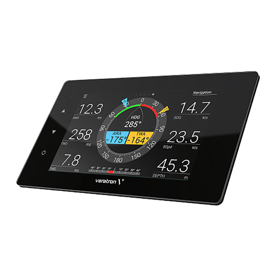
DATA SCREENS NAVDASH LAYOUT The NavDash layout is available in three different configurations with respectively two, three, and eight round gauges displayed. Every layout is displayed in blue or amber color palette, and in day or night mode depending on the current display setup. -
Page 26: Screens Configuration
SCREENS CONFIGURATION SCREENS CONFIGURATION To access the screens configuration settings, enter the HOME screen by pressing the MENU button and select [SCREENS CONFIGURATION] to enter the settings. Access the HOME screen by pressing [MENU] and select [SCREENS CONFIGURATION] to enter the screens’... - Page 27 SCREENS CONFIGURATION Scroll through the customizable items by pressing the UP and DOWN buttons. Press [ENTER] to select the item to be customized. Once an item is selected it will be highlighted in red color. Press the UP/DOWN buttons to modify the data displayed on that item.
-
Page 28: System Configuration
SYSTEM CONFIGURATION SYSTEM CONFIGURATION To access the system settings, enter the HOME screen by pushing [MENU] and selecting [SYSTEM CONFIGURATION] to enter the screens’ configuration. MENU STRUCTURE B001517... -
Page 29: Operating The System Config Menu
SYSTEM CONFIGURATION OPERATING THE SYSTEM CONFIG MENU NOTE: the underlined value/command is the factory default one. Setting Description Possible values / commands Display > Brightness of the display for the day mode. 0–7, Auto Illumination Day NOTE: this setup affects all the EasyLink gauges too. - Page 30 SYSTEM CONFIGURATION Setting Description Possible values / commands Damping > Damping for wind and heading displayed data. • Wind damping/ • Heading damping • Medium • High Clock > Clock format. • 12 h Clock format 24 h • Clock > Time zone setup.
-
Page 31: Units
SYSTEM CONFIGURATION UNITS Setting Metric Imperial Nautical Custom Distance km, mi, nm Boat speed km/h km/h, mph, kn Wind speed km/h km/h, kn, m/s, bft Depth m, ft Pressure bar, psi, kPa Fuel L, gal Fuel flow L/h, gph Temperature °C °F °F... -
Page 32: Sensor Configurations
SENSOR CONFIGURATION SENSOR CONFIGURATION To access the sensors’ settings, enter the HOME screen by pressing the MENU button and select [SENSOR CONFIGURATION] to access it. MENU STRUCTURE Setting Description Possible values Engine 1 connector Configure the sensors connected to the display through the analogue inputs of the Engine 1 connector (see “Electrical Connections”). -
Page 33: Configure A Sensor Connected To The Display
SENSOR CONFIGURATION CONFIGURE A SENSOR CONNECTED TO THE DISPLAY B001517... - Page 34 Select what kind of sensor is connected to that input. See the menu diagram for the complete list of supported sensors. Select “Custom” for importing the complete input configuration from the PC Veratron Configuration Tool. CONFIGURE THE NMEA 2000 OUTPUT The measured value for the configured analog sensor is also transmitted over NMEA 2000, so the VMH display will act as a source for that data.
-
Page 35: Fuel Level Sensor Calibration
SENSOR CONFIGURATION FUEL LEVEL SENSOR CALIBRATION In the input configuration menu described before, select “Calibration” to open the sensor’s calibration options. Select Tank volume to set the tank’s capacity (not mandatory). Select Sensor type, then select the sensor type among the proposed standard ones. Select Calibration, then select the one or three- point calibration procedure (Do 1 point cal/Do 3- point cal). -
Page 36: Custom Sensors Configuration
SENSOR CONFIGURATION CUSTOM SENSORS CONFIGURATION In the bottom part of the Sensor Configuration panel, it is possible to fully customize the configuration of every analog port of your VMH display. NOTE: this operation still requires you to perform some setting on the display itself (set the input to “Custom”... -
Page 37: Default Calibrations
SENSOR CONFIGURATION Manually set the 5-points calibration into the table [D] for the selected sensor. The graph [G] will display the calibration being set. The example above is for a standard 3-180 fuel level sensor. Ω Upload the configuration to the display. Press the SET button [F] to write the configuration for the specific pin. -
Page 38: Alarms
ALARMS ALARMS The VMH display can show active alarms coming from either NMEA 2000, SAE J1939, or from the analogue sensors directly connected to it. Engine alarms concern all engines on the network. MENU STRUCTURE Active alarms Alarm active Config alarm popup Depth shallow Value Buzzer... -
Page 39: Acknowledge An Alarm
ALARMS ACKNOWLEDGE AN ALARM When an alarm is triggered, the Alarm notification pop-up appears and the buzzer sounds (if connected and configured). To acknowledge the alarm and mute the buzzer, press the touchscreen: the pop-up notification is closed, and the alarm is saved in the Active alarms screen. The alarm remains displayed in the Active alarms screen as long as it remains active, and a warning icon is displayed in the bottom side of every screen to remind you that an alarm is currently active. -
Page 40: Configure A Local Alarm
Local alarm input External digital switch (low active alarm). Refer to “Connections’ diagram”. The name of the alarm triggered can be configured in the Veratron Configuration Tool. Contact your dealer for more information. Min RPM Engine related alarms are only triggered 0 –... -
Page 41: Configure A Can Alarm
ALARMS CONFIGURE A CAN ALARM 1. Press the MENU button and select [ALARMS] > [Setup] 2. Select [CAN] and then the [NMEA 2000] or [SAE J1939] 3. Choose the alarm to activate and select [Active] > [Yes], the alarm parameters will appear 4. -
Page 42: Troubleshooting
TROUBLESHOOTING TROUBLESHOOTING Problem Root cause Solution The values Incorrect sensor configuration. Check the configuration in the Sensors menu. displayed are not Sensor connected incorrectly. Check the connection, refer to the Installation as expected. Instructions. The NMEA 2000 network Check the connections and that there is a backbone has not been termination at both the beginning and end of the created correctly. -
Page 43: Technical Data
TECHNICAL DATA TECHNICAL DATA GENERAL FEATURE Material Aluminum case PC-FR back cover Mineral glass front screen Display IPS TFT 7” – 800x480 – Transmissive touch screen Full 24 bit / 16 mio. colors • Connectors 2x Molex MX150 12 pin •... -
Page 44: Compliance
TECHNICAL DATA COMPLIANCE Compliance CE, UKCA, Reach, RoHS, UL94 Directives 2014/30/EU (Electromagnetic compatibility) 2011/65/EU (Hazardous substances in electrical and electronic equipment) Reference standards IEC 60945: 2002-08 (environmental class: exposed) SUPPORTED NMEA 2000 MESSAGES Description Description J1939 Generator Average Basic AC 65030 Water depth 128267... -
Page 45: Spare Parts And Accessories
NMEA 2000 drop cable – 0.5m A2C9624370001 NMEA 2000 drop cable – 2m A2C9624380001 NMEA 2000 drop cable – 6m A2C9624400001 NMEA 2000 terminator - Male A2C3931100001 NMEA 2000 terminator - Female A2C3931060001 For all available accessories, visit www.Veratron.com. B001517... - Page 46 Any distribution, translation, or reproduction of this document, in whole or in part, is strictly prohibited without the prior written permission of Veratron AG, except as noted below: - Print the document in its original format, in whole or in part.
- Page 47 VMH 70 MARINE ANZEIGE BEDIENUNGSANLEITUNG rev. AA B001517...
- Page 48 INHALTSVERZEICHNIS INHALTSVERZEICHNIS EINFÜHRUNG ............3 Motorstunden ..............24 Architektur ................. 3 Zurückgelegte Entfernung ........24 NavDash Layout ............24 SICHERHEITSHINWEISE ........4 BILDSCHIRMKONFIGURATION ..... 25 Während des Einbaus beachten ......4 Nach dem Einbau beachten ........5 SYSTEMEINSTELLUNGEN ........ 27 Elektrischer Anschluss ..........
-
Page 49: Einführung
Mit der NMEA 2000-Anbindung können Sie Navigationsdaten von anderen Geräten im Netzwerk anzeigen, wie z. B. Wind, Kompass, GPS, Geschwindigkeit und Tiefendaten. ARCHITEKTUR Es folgt ein Beispiel für eine Anwendung mit einem VMH 70-Display, das als Gateway und als NMEA 2000- Monitor verwendet wird. B001517... -
Page 50: Sicherheitshinweise
SICHERHEITSHINWEISE SICHERHEITSHINWEISE WARNUNG • Nicht rauchen! Kein offenes Feuer oder Wärmequellen! • Das Produkt wurde unter Beachtung der • Beachten Sie eventuelle Veränderungen am grundlegenden Sicherheitsanforderungen der Fahrzeug, die beim Einbau zu berücksichtigen EG-Richtlinien und dem anerkannten Stand sind! • Für den Einbau sind Grundkenntnisse der der Technik entwickelt, gefertigt und geprüft. -
Page 51: Nach Dem Einbau Beachten
SICHERHEITSHINWEISE • Bei notwendigen Arbeiten ohne eingegebenen Werte verlieren und neu programmiert werden müssen. Spannungsunterbrechung darf nur mit • Lassen Sie bei Bootsmotoren vor Beginn der isoliertem Werkzeug gearbeitet werden. • Benutzen Sie zum Messen von Spannungen Arbeiten im Motorraum bei Benzinmotoren den Motorraumlüfter laufen. - Page 52 SICHERHEITSHINWEISE • Achtung: Kurzschlussgefahr durch fehlerhafte • Achten Sie besonders auf einwandfreie Verbindungsstellen oder beschädigte Kabel. Masseverbindungen. • Kurzschlüsse im Bordnetz können • Falschanschlüsse können zu Kurzschlüssen Kabelbrände, Batterieexplosionen und führen. Schliessen Sie die Kabel nur Beschädigungen anderer elektronischer entsprechend dem elektrischen Anschlussplan Systeme verursachen.
-
Page 53: Installation
INSTALLATION INSTALLATION WARNUNG Vor Beginn der Arbeiten ist der Minuspol der Batterie abzuklemmen, da sonst Kurzschlussgefahr besteht. Wenn das Fahrzeug über Zusatzbatterien verfügt, müssen ggf. auch die Minuspole dieser Batterien abgeklemmt werden! Kurzschlüsse können Kabelbrände, Batterieexplosionen und Beschädigungen von anderen elektronischen Systemen verursachen. Bitte beachten Sie, dass beim Abklemmen der Batterie alle flüchtigen elektronischen Speicher ihre eingegebenen Werte verlieren und neu programmiert werden müssen. -
Page 54: Panel-Montage
INSTALLATION PANEL-MONTAGE WARNUNG • Bohren Sie keine Löcher oder Montageöffnungen in tragende oder stabilisierende Elemente! • Der Montageort muss einen ausreichenden Freiraum hinter den Montagebohrungen aufweisen. 1. Mit Hilfe der Schablone (siehe nächste Seite) und unter Berücksichtigung der Geräteabmessungen [A] ein rechteckiges Loch in die Platte einarbeiten. - Page 55 INSTALLATION B001517...
-
Page 56: Elektrische Anschlüsse
ELEKTRISCHE ANSCHLÜSSE ELEKTRISCHE ANSCHLÜSSE WARNUNG Beachten Sie die Sicherheitsvorschriften, die im Abschnitt "Elektrische Anschlüsse" des Kapitels • "Sicherheitshinweise" in diesem Dokument beschrieben sind! MOTOR STECKER 1 [A] Pin Nr. Kabelfarbe Beschreibung KL. 30 – Batterie Plus 12 / 24 V Schwarz KL. -
Page 57: Motor Stecker 2 [B]
ELEKTRISCHE ANSCHLÜSSE MOTOR STECKER 2 [B] Pin Nr. Kabelfarbe Beschreibung Rosa Personalisierbarer Alarmeingang Schwarz KL. 31 - Masse Weiss Alarm-Ausgang Grün Frequenzsensor-Signal - RPM Blau SAE J1939 - CAN High Blau / Weiss SAE J1939 - CAN Low Gelb 0-5 V Sensoreingang Grau Resistiver Sensoreingang Braun... -
Page 58: Nmea 2000®-Anschluss [D]
ELEKTRISCHE ANSCHLÜSSE NMEA 2000®-ANSCHLUSS [D] Pin Nr. Beschreibung Abschirmung NET-S (V+) NET-C (V-) NET-H (CAN High) Micro-C M12 5-poliger Stecker NET-L (CAN Low) Stecker, Kabelansicht Sobald die Installation abgeschlossen ist, können Sie das Gerät über den entsprechenden Anschluss [D] mit dem NMEA 2000® -Netzwerk verbinden. -
Page 59: Elektrischer Schaltplan
ELEKTRISCHE ANSCHLÜSSE ELEKTRISCHER SCHALTPLAN Bezeichnungen im Schaltplan Batt - KL.30 – Batterie Plus 12/24 V S1 - Tag/Nacht-Schalter (nicht enthalten) RES - Widerstandsabhängige Eingänge IGN - KL. 15 - Zündung Plus S2 - Zündschloss RPM – Frequenzabhängige Eingänge GND - KL. 31 - Masse F1 - 3A-Sicherung (nicht enthalten) ALARM - Externer digitaler Alarm Illum. -
Page 60: Anschluss Des Drehzahlsensors
ELEKTRISCHE ANSCHLÜSSE ANSCHLUSS DES DREHZAHLSENSORS Das Motordrehzahlsignal kann von verschiedenen Quellen stammen, z. B. von der Klemme "W" der Lichtmaschine, der Klemme "1" der Zündspule oder von spezifischen Sensoren wie einem Drehgeber oder einem induktiven Sensor. Es ist ratsam, Sensoren mit isolierter Masse zu verwenden, und es muss sichergestellt werden, dass die Sensormasse mit der Anzeigemasse verbunden ist, um falsche Messwerte zu vermeiden. -
Page 61: Resistiver Sensoranschluss
ELEKTRISCHE ANSCHLÜSSE RESISTIVER SENSORANSCHLUSS Jeder Sensor, der an einen resistiven Eingang des Displays angeschlossen wird, muss wie in der Abbildung gezeigt angeschlossen sein. Es ist ratsam, Sensoren mit isolierter Masse zu verwenden, und es muss sichergestellt werden, dass die Sensormasse mit der Anzeigemasse verbunden ist, um falsche Messwerte zu vermeiden. Temperatursensor mit isolierter Masse Tankfüllstandssensor angeschlossen Drucksensor mit isolierter Masse... -
Page 62: Priorität Von Datenquellen
ELEKTRISCHE ANSCHLÜSSE PRIORITÄT VON DATENQUELLEN Wenn die gleichen Daten von mehr als einer Quelle für denselben Motor verfügbar sind, wird die Priorität des empfangenen Signals folgendermassen gewertet: • Analoger Eingang • SAE J1939 • NMEA 2000 B001517... -
Page 63: Erste Schritte
Im Normalbetrieb zeigt das Display eine von bis zu zehn personalisierbaren Datenseiten an. Wischen Sie auf dem Touchscreen nach links oder rechts, um durch diese Datenseiten zu blättern. Um das Menü des VMH 70 zu öffnen, drücken Sie auf das Feld MENU in der unteren linken Ecke des Bildschirms. Diese Taste führt zum Hauptmenü, welches die folgenden vier Untermenus enthält:... -
Page 64: Funktionen Der Menütasten
ERSTE SCHRITTE FUNKTIONEN DER MENÜTASTEN Wenn Sie das Menü bedienen, werden diese Tasten am rechten Rand des Displays angezeigt. Benutzen Sie sie, um durch das Menü zu navigieren. Es ist nicht möglich, das Menü durch Hoch- und Runterwischen der Liste zu bedienen. Schaltfläche Name Funktion... -
Page 65: Einstellen Des Tag/Nacht-Modus
6. Aktivieren/Deaktivieren von lokalen, NMEA 2000- und J1939-Alarmen (siehe "Alarmverwaltung"). HOCHLADEN EINES BENUTZERDEFINIERTEN SPLASH-LOGOS Ein benutzerdefiniertes Splash-Logo kann mit dem Veratron Configuration Tool von einem PC geladen werden. Dieses Logo wird jedes Mal während des Startvorgangs angezeigt. Weitere Informationen finden Sie im Benutzerhandbuch zum Veratron Configuration Tool oder bei Ihrem Veratron-Händler. -
Page 66: Datenseiten
DATENSEITEN DATENSEITEN Die Datenbildschirme zeigen die von den verschiedenen Quellen empfangenen Daten an. Das Display kann bis zu 10 Datenbildschirme speichern. Standardmässig werden fünf Bildschirme angezeigt [Dual Engine, NavDash, Quad Data, Battery Screen, Video]. Falls es aktive Alarme gibt, wird die Alarmseite nach der letzten Datenseite angezeigt. BILDSCHIRME BLÄTTERN Streichen Sie mit dem Finger horizontal über den Touchscreen, um durch die Seiten zu blättern. - Page 67 DATENSEITEN Ladedruck, Trimmung, Motorkühlmitteltemperatur, Motordrehzahlen, die Batteriespannung, die Batteriespannung, Kraftstoffverbrauch. Ruderlage, sowie die Geschwindigkeit und der eingelegte Gang angezeigt. SINGLE DATA-LAYOUT TRIPLE DATA-LAYOUT Einzelne Datenanzeige. Der Datenwert ist numerisch Drei Felder, mit je ein oder drei Daten. oder wird durch eine Anzeige dargestellt. QUAD DATA-LAYOUT NAV DASH-LAYOUT Vier Felder, mit je ein oder drei Daten.
-
Page 68: Unterstützte Daten
DATENSEITEN BATTERY MONITOR LAYOUT VIDEO-BILDSCHIRM Bildschirm für die Batterieüberwachung mit Zeigt das von der externen Videokamera empfangene umfangreichen Batterieinformationen, die vom Video an. Intelligenten Batteriesensor (IBS) stammen können. UNTERSTÜTZTE DATEN Eingang Ausgang Icon Daten Einheit NMEA NMEA SAE J1939 Analog 2000 2000 Umdrehungen... - Page 69 DATENSEITEN Eingang Ausgang Icon Daten Einheit NMEA NMEA SAE J1939 Analog 2000 2000 Frischwasserstand (Tank: 1-4) Abwasserstand (Tank: 1-4) °C, °F Wassertemperatur Aussentemperatur °C, °F Luftdruck BARO ° Kurs zu Grund (COG) ° Ausrichtung Scheinbarer Windwinkel ° (AWA) Scheinbare Wind- km/h geschwindigkeit (AWS) Wahrer Windwinkel (TWA)
-
Page 70: Motorstunden
DATENSEITEN MOTORSTUNDEN Wenn keine Daten aus dem NMEA-2000-Netzwerk empfangen werden, berücksichtigt das Gerät den intern gezählten Wert. Die Zeit wird als Motorstunden gezählt, wenn die Motordrehzahl mehr als 300 RPM beträgt. Bei Vorhandensein von Daten aus dem NMEA 2000-Netzwerk berücksichtigt der Indikator die vom Netzwerk empfangenen Daten nur, wenn sie höher sind als die internen Daten. -
Page 71: Bildschirmkonfiguration
BILDSCHIRMKONFIGURATION BILDSCHIRMKONFIGURATION Um auf die Einstellungen für die Bildschirmkonfiguration zuzugreifen, rufen Sie das Hauptmenu mit der Schaltfläche [MENU] auf, und wählen Sie [SCREEN CONFIGURATION], um die Personalisierung zu starten. Rufen Sie das Hauptmenu auf, indem Sie [MENU] drücken und [SCREEN CONFIGURATION] wählen. Blättern Sie durch die Favoritenbildschirme, bis derjenige angezeigt wird, der angepasst (oder gelöscht) werden soll, und drücken Sie zur... - Page 72 BILDSCHIRMKONFIGURATION Blättern Sie durch die anpassbaren Elemente, indem Sie [AUF] und [AB] drücken. Drücken Sie [ENTER], um das Element auszuwählen, das angepasst werden soll. Sobald ein Element ausgewählt ist, wird es in roter Farbe hervorgehoben. Drücken Sie die AUF/AB-Tasten, um die Daten zu ändern, die an dieser Stelle angezeigt werden sollen.
-
Page 73: Systemeinstellungen
SYSTEMEINSTELLUNGEN SYSTEMEINSTELLUNGEN Um auf die Systemeinstellungen zuzugreifen, drücken Sie auf [MENU] und wählen Sie [SYSTEM CONFIGURATION], um die Konfiguration der Bildschirme aufzurufen. MENÜSTRUKTUR B001517... -
Page 74: System Configurations Menü-Bedienung
SYSTEMEINSTELLUNGEN SYSTEM CONFIGURATIONS MENÜ-BEDIENUNG HINWEIS: Der unterstrichene Wert/Befehl ist die Werkseinstellung. Einstellung Beschreibung Mögliche Werte / Befehle Display > Helligkeit des Displays für den Tagesmodus. 0-7, Auto Illumination Day HINWEIS: Diese Einstellung wirkt sich auch auf alle EasyLink-Messgeräte aus. Display > Helligkeit des Displays für den Nachtmodus. - Page 75 SYSTEMEINSTELLUNGEN Einstellung Beschreibung Mögliche Werte / Befehle Units Masseinheit für die angezeigten Daten. Metrisch • Imperial • Nautisch • Benutzerdefiniert • Damping > Dämpfung für Wind- und Kursdaten. • Wind damping/ Schwach • Heading damping Mittel • Stark • Clock > Anzeigeformat der Uhr.
-
Page 76: Einheiten
SYSTEMEINSTELLUNGEN EINHEITEN Einstellung Metrisch Imperial Nautisch Benutzerdefiniert Entfernungen km, mi, nm Bootsgeschwindigkeit km/h km/h, mph, kn Windgeschwindigkeit km/h km/h, kn, m/s, bft Tiefe m, ft Druck bar, psi, kPa Kraftstoff L, gal Kraftstoffverbrauch L/h, gph Temperaturen °C °F °F °C, °F SAE J1939-GATEWAY Das VMH-Display ist mit zwei individuellen SAE J1939-Anschlüssen ausgestattet, über die Sie Ihre CAN- Motoren mit dem Display verbinden und die von ihnen kommenden digitalen Daten lesen können. -
Page 77: Sensor-Konfigurationen
SENSOR-KONFIGURATIONEN SENSOR-KONFIGURATIONEN Um auf die Einstellungen der Sensoren zuzugreifen, rufen Sie das Hauptmenu auf, indem Sie auf [MENU] drücken, und wählen Sie [SENSOR CONFIGURATION], um darauf zuzugreifen. MENÜSTRUKTUR Mögliche Einstellung Beschreibung Werte Engine 1 Konfigurieren Sie die Sensoren, die über die Analogeingänge des «Motor connector 1-Anschlusses»... -
Page 78: Konfigurieren Eines An Das Display Angeschlossenen Sensors
SENSOR-KONFIGURATIONEN KONFIGURIEREN EINES AN DAS DISPLAY ANGESCHLOSSENEN SENSORS B001517... - Page 79 Eingang angeschlossen ist. Die vollständige Liste der unterstützten Sensoren für den gewählten Eingang wird im Menu dargestellt. Wählen Sie [CUSTOM], um die komplette Eingangskonfiguration aus dem PC Veratron Configuration Tool zu importieren. DEN NMEA 2000-AUSGANG KONFIGURIEREN Der Messwert für den konfigurierten Analogsensor wird ebenfalls über NMEA 2000 übertragen, so dass...
-
Page 80: Kalibrierung Des Kraftstoffstandssensors
SENSOR-KONFIGURATIONEN KALIBRIERUNG DES KRAFTSTOFFSTANDSSENSORS Wählen Sie im zuvor beschriebenen Eingangs- Konfigurationsmenü [Calibration], um die Kalibrierungsoptionen des Sensors zu öffnen. Wählen Sie [Tank Volume], um das Fassungsvermögen des Tanks einzustellen (nicht obligatorisch). Wählen Sie [Sensor Type], dann wählen Sie den Sensortyp aus den vorgeschlagenen Standardtypen. -
Page 81: Benutzerdefinierte Sensorkonfiguration
SENSOR-KONFIGURATIONEN BENUTZERDEFINIERTE SENSORKONFIGURATION Im unteren Teil der Sensorkonfigurations-Seite können Sie die Konfiguration jedes analogen Anschlusses Ihres VMH-Displays vollständig anpassen. HINWEIS: Für diesen Vorgang müssen Sie noch einige Einstellungen am Display selbst vornehmen (stellen Sie den Eingang auf "Custom" und wählen Sie die Dateninstanz aus). Wählen Sie das Gerät, das angepasst werden soll, aus der Dropdown-Liste [A]. -
Page 82: Standard-Kalibrierungen
SENSOR-KONFIGURATIONEN Geben Sie die 5-Punkte-Kalibrierung manuell in die Tabelle [D] für den ausgewählten Sensor ein. Die Grafik [G] zeigt die eingestellte Kalibrierung an. Das obige Beispiel bezieht sich auf einen Standard-3-180- Ω Kraftstofffüllstandssensor. Laden Sie die Konfiguration auf das Display hoch. Drücken Sie die SET-Taste [F], um die Konfiguration für den jeweiligen Pin zu schreiben. -
Page 83: Einstellen Des
SENSOR-KONFIGURATIONEN EINSTELLEN DES GESCHWINDIGKEITSKORREKTURFAKTORS Mit dem Geschwindigkeitskorrekturfaktor können Sie die Geschwindigkeit zum Wasser (STW, Speed through water) an die tatsächliche Geschwindigkeit anpassen. Wenn die gemessene Geschwindigkeit um mehr als 0,5 kn von der tatsächlichen Bootsgeschwindigkeit abweicht, kann dieser Faktor angepasst werden. -
Page 84: Alarme
ALARME ALARME Das VMH-Display kann aktive Alarme anzeigen, die entweder von NMEA 2000, SAE J1939 oder von den angeschlossenen analogen Sensoren stammen. Motoralarme betreffen alle Motoren im Netz. MENÜSTRUKTUR Active alarms Alarm active Config alarm popup Depth shallow Value Buzzer Alarm active Local alarm input Alarm active... -
Page 85: Einen Alarm Quittieren
ALARME EINEN ALARM QUITTIEREN Wenn ein Alarm ausgelöst wird, erscheint das Pop-up-Fenster für die Alarmbenachrichtigung und der Buzzer ertönt (falls angeschlossen und konfiguriert). Um den Alarm zu bestätigen und den Buzzer stumm zu schalten, drücken Sie auf den Touchscreen: Die Pop-up-Benachrichtigung wird geschlossen und der Alarm wird auf dem Bildschirm «Active Alarms»... -
Page 86: Einen Lokalen Alarm Konfigurieren
Local alarm input Externer digitaler Schalter (Low-Aktiver Nein Alarm). Siehe "Elektrische Anschlüsse". Der Name des ausgelösten Alarms kann im Veratron Configuration Tool konfiguriert werden. Wenden Sie sich für weitere Informationen an Ihren Händler. Min RPM Motorbezogene Alarme werden nur 0 – 990 RPM ausgelöst, wenn die Motordrehzahl diesen... -
Page 87: Konfigurieren Eines Can-Alarms
ALARME KONFIGURIEREN EINES CAN-ALARMS 1. Drücken Sie die MENU-Taste und wählen Sie [ALARMS] > [Setup]. 2. Wählen Sie [CAN] und dann die Option [NMEA 2000] oder [SAE J1939]. 3. Wählen Sie den Alarm, der aktiviert werden soll, und wählen Sie [Active] > [Yes]; die Alarmparameter werden angezeigt 4. -
Page 88: Fehlersuche
FEHLERSUCHE FEHLERSUCHE Problem Grundlegende Ursache Lösung Die angezeigten Falsche Sensorkonfiguration. Überprüfen Sie die Konfiguration im Menü Werte sind nicht Sensoren. wie erwartet. Sensor falsch angeschlossen. Überprüfen Sie den Anschluss, siehe Installationsanleitung. Der NMEA 2000-Backbone ist Überprüfen Sie die Verbindungen und dass nicht korrekt erstellt worden. -
Page 89: Technische Daten
TECHNISCHE DATEN TECHNISCHE DATEN ALLGEMEINES Material Aluminium-Gehäuse PC-FR Rückwand Frontscheibe aus Mineralglas Anzeige IPS TFT 7" - 800x480 - Transmissiver Touchscreen Volle 24 Bit / 16 Mio. Farben Steckverbinder • 2x Molex MX150 12-polig • 1x NMEA 2000 Micro-C M12 5-polig •... -
Page 90: Konformität
TECHNISCHE DATEN KONFORMITÄT Einhaltung der Vorschriften CE, UKCA, Reach, RoHS, UL94 Richtlinien 2014/30/EU (Elektromagnetische Verträglichkeit) 2011/65/EU (Gefährliche Stoffe in Elektro- und Elektronikgeräten) Referenznormen IEC 60945: 2002-08 (Umweltklasse: ausgesetzt) UNTERSTÜTZTE NMEA 2000-NACHRICHTEN Beschreibung Beschreibung J1939 Generator Average Basic AC 65030 Water depth 128267 Quantities J1939 Diagnostic Message #1... -
Page 91: Ersatzteile Und Zubehör
NMEA 2000 T-Verteiler A2C3931270002 NMEA 2000 Verbindungskabel - 0,5m A2C9624370001 NMEA 2000 Verbindungskabel - 2m A2C9624380001 NMEA 2000 Verbindungskabel - 6m A2C9624400001 NMEA 2000 Abschlusswiderstand - Stecker A2C3931100001 NMEA 2000 Abschlusswiderstand - Buchse A2C3931060001 Alle verfügbaren Zubehörteile finden Sie unter www.Veratron.com. B001517... - Page 92 - Drucken Sie das Dokument ganz oder teilweise in seinem ursprünglichen Format. - Unveränderte Übernahme der Inhalte und Erklärung der Veratron AG als Urheberrechtsinhaberin. Die Veratron AG behält sich das Recht vor, ohne vorherige Ankündigung Änderungen oder Verbesserungen an dieser Dokumentation vorzunehmen. Anfragen für Genehmigungen, zusätzliche Exemplare dieses Handbuchs oder technische Informationen zu diesem Handbuch sollten an die Veratron AG gerichtet werden.
- Page 93 DISPLAY MULTIFUNZIONE VMH 70 MANUALE UTENTE rev. AA B001517...
- Page 94 INDICE INDICE INTRODUZIONE ............ 3 Layout NavDash ............24 Architettura ................ 3 CONFIGURAZIONE DELLE PAGINE DATI .. 25 INDICAZIONI PER LA SICUREZZA ....4 CONFIGURAZIONE DEL DISPLAY ....27 Sicurezza durante il montaggio ........ 4 Struttura del menu ............27 Sicurezza dopo il montaggio........
-
Page 95: Introduzione
GPS, velocità e profondità. ARCHITETTURA Di seguito è riportato un esempio di applicazione con un display VMH 70, in una configurazione mista in cui i dati provengono sia come sensori analogici che da NMEA 2000. -
Page 96: Indicazioni Per La Sicurezza
• Modifiche o manipolazioni del prodotto per cui è previsto. Le conseguenze di un utilizzo improprio del prodotto possono veratron possono compromettere la sicurezza. causare lesioni a persone e danni a cose o Non sono pertanto ammesse manovre di all’ambiente. Prima del montaggio accertarsi modifica o manipolazione. -
Page 97: Sicurezza Dopo Il Montaggio
INDICAZIONI PER LA SICUREZZA memoria elettronica transitoria andranno persi assolutamente alle indicazioni di sicurezza del e dovranno essere riprogrammati. produttore dell’utensile. • Nelle barche con motore a benzina accendere • Per i lavori per cui è necessario interrompere la il ventilatore del motore prima di iniziare a tensione utilizzare esclusivamente un utensile lavorare al vano motore. - Page 98 INDICAZIONI PER LA SICUREZZA • I corto circuiti alla rete di bordo possono bruciare cavi, causare esplosioni delle batterie e danni di altri sistemi elettronici, perciò tutti i collegamenti dell’alimentazione di tensione vanno dotati di giunti di testa saldabili e devono essere sufficientemente isolati.
-
Page 99: Installazione
INSTALLAZIONE INSTALLAZIONE ATTENZIONE Prima di iniziare a lavorare staccare il morsetto del polo negativo della batteria per evitare il rischio di corto circuito. Se il veicolo è dotato di batterie supplementari occorre staccare eventualmente anche il polo negativo di tutte le batterie. I corto circuiti possono bruciare i cavi, far esplodere le batterie e causare danni ad altri sistemi elettronici. -
Page 100: Montaggio A Pannello
INSTALLAZIONE MONTAGGIO A PANNELLO ATTENZIONE • Non praticare fori o aperture di installazione nelle travi di sostegno o di stabilizzazione! • La posizione di montaggio deve avere uno spazio sufficiente dietro i fori o le aperture di montaggio. 1. Praticare un foro rettangolare nel pannello utilizzando la dima di foratura (vedere la pagina successiva di questo documento) e tenendo conto delle dimensioni del... - Page 101 INSTALLAZIONE B001517...
-
Page 102: Collegamenti Elettrici
COLLEGAMENTI ELETTRICI COLLEGAMENTI ELETTRICI ATTENZIONE Fare riferimento alle norme di sicurezza descritte nella sezione collegamenti elettrici del capitolo • Informazioni sulla sicurezza di questo documento! CONNETTORE ENGINE 1 [A] Colore Descrizione KL. 30 – Positivo permanente 12 / Rosso 24 V Nero KL. -
Page 103: Connettore Engine 2 [B]
COLLEGAMENTI ELETTRICI CONNETTORE ENGINE 2 [B] Colore Descrizione Ingresso di allarme Rosa configurabile Nero KL. 31 - Massa Bianco Uscita di allarme Segnale del sensore di Verde frequenza - RPM SAE J1939 - CAN Hi Blu / Bianco SAE J1939 - CAN Low Giallo Ingresso sensore 0-5 V Grigio... -
Page 104: Connettore Nmea 2000® [D]
COLLEGAMENTI ELETTRICI CONNETTORE NMEA 2000® [D] Descrizione Schermatura NET-S (V+) NET-C (V-) NET-H (CAN H) Connettore Micro-C M12 5 poli NET-L (CAN L) maschio, vista cavo Una volta completata l'installazione, è possibile interfacciare il dispositivo alla rete NMEA 2000® attraverso il connettore dedicato [D]. -
Page 105: Schema Elettrico
COLLEGAMENTI ELETTRICI SCHEMA ELETTRICO Denominazioni nello schema elettrico Batt - Term.30 – Positivo permanente 12/24 V S1 - Interruttore modalità giorno/notte (non IGN - Term. 15 - Positivo di accensione incluso) RES - Ingressi resistivi GND - Term. 31 - Massa S2 - Chiave di accensione RPM - Ingressi in frequenza Illum. -
Page 106: Collegamento Del Contagiri
COLLEGAMENTI ELETTRICI COLLEGAMENTO DEL CONTAGIRI Il segnale del contagiri può essere ottenuto da diverse fonti, rispettivamente dal terminale "W" dell'alternatore, dal terminale "1" della bobina di accensione o da sensori dedicati come un generatore o un sensore induttivo. È consigliabile utilizzare sensori con massa isolata ed è necessario assicurarsi che la massa del sensore sia collegata alla massa del display per evitare letture errate. -
Page 107: Collegamento Dei Sensori Resistivi
COLLEGAMENTI ELETTRICI COLLEGAMENTO DEI SENSORI RESISTIVI Qualsiasi sensore collegato a un ingresso resistivo del display deve essere collegato come indicato in figura. È consigliabile utilizzare sensori con massa isolata ed è necessario assicurarsi che la massa del sensore sia collegata alla massa del display per evitare letture errate. Sensore di livello collegato Sensore di temperatura con massa Sensore di pressione con massa isolata... -
Page 108: Priorità Dei Segnali Ricevuti
COLLEGAMENTI ELETTRICI PRIORITÀ DEI SEGNALI RICEVUTI Se lo stesso dato fosse ricevuto da più di una sorgente, la priorità del segnale ricevuto è la seguente: • Ingresso analogico • SAE J1939 • NMEA 2000 B001517... -
Page 109: Per Iniziare
La luminosità del display può essere modificata in qualsiasi momento premendo i pulsanti touch sul lato sinistro del display. MODALITÀ STANDBY Il display VMH 70 supporta una modalità standby, in cui il display viene spento per ridurre il consumo di corrente o semplicemente per non averlo illuminato in condizioni di oscurità quando non è necessario. -
Page 110: Funzioni Dei Pulsanti Del Menu
PER INIZIARE FUNZIONI DEI PULSANTI DEL MENU Quando si accede ad un menu, una serie di pulsanti vengono visualizzati sul bordo destro del display. Utilizzarli per navigare nel menu come descritto nella tabella sottostante. Pulsante Nome Funzione • INDIETRO Ritorno al menu precedente •... -
Page 111: Impostare La Modalità Giorno/Notte
È possibile caricare un logo personalizzato da PC utilizzando il Veratron Configuration Tool. Tale logo verrà visualizzato ogni volta durante il processo di avvio. Per ulteriori informazioni, consultare il manuale d'uso del Veratron Configuration Tool o contattare il proprio rivenditore Veratron. -
Page 112: Pagine Dati
PAGINE DATI PAGINE DATI Le pagine dati mostrano ile informazioni ricevuti dalle varie sorgenti. Il display può memorizzare fino a 10 schermate. Di default, vengono visualizzate cinque schermate [Dual Engine, NavDash, Quad Data, Battery Screen, Video]. La pagina degli allarmi appare in coda alle schermate definite se ci sono allarmi attivi. SCORRIMENTO DELLE SCHERMATE Per scorrere le pagine, passare il dito sul touch screen in senso orizzontale. - Page 113 PAGINE DATI Layout SINGLE Layout TRIPLE Visualizzazione di un singolo dato numerico. Da tre a nove dati numerici. Layout QUAD Layout NAV DASH Da quattro a dodici dati numerici. Questi layout consentono di visualizzare i dati in modo analogico. Sono disponibili tre varianti di due, tre o otto indicatori sullo schermo.
-
Page 114: Dati Supportati
PAGINE DATI DATI SUPPORTATI Ingresso Uscita Icona Dati Unità NMEA NMEA SAE J1939 Analogico 2000 2000 giri al minuto Giri del motore Trim Pressione di bar, psi, kPa sovralimentazione del motore Temperatura del liquido di °C , °F raffreddamento del motore Tensione della batteria gal/h , L/h Consumo di carburante... -
Page 115: Ore Motore
PAGINE DATI Ingresso Uscita Icona Dati Unità NMEA NMEA SAE J1939 Analogico 2000 2000 Angolo del vento apparente ° (AWA) Velocità del vento km/h apparente (AWS) Angolo di vento vero (TWA) km/h Velocità del vento reale km/h (TWS) Direzione del vento vero °... -
Page 116: Layout Navdash
PAGINE DATI LAYOUT NAVDASH Il layout NavDash è disponibile in tre diverse configurazioni con due, tre, o otto indicatori circolari. Ogni layout viene visualizzato in un colore blu o ambra e in modalità giorno o notte, a seconda dell'impostazione corrente del display. Ogni indicatore può... -
Page 117: Configurazione Delle Pagine Dati
CONFIGURAZIONE DELLE PAGINE DATI CONFIGURAZIONE DELLE PAGINE DATI Per accedere alle impostazioni di configurazione delle schermate, selezionare [SCREENS CONFIGURATION] nel MENU principale. Accedere alla schermata HOME premendo [MENU] e selezionare [SCREENS CONFIGURATION]. Scorrere le schermate preferite fino a visualizzare quella da personalizzare (o eliminare) e premere [ENTER] per confermare. - Page 118 CONFIGURAZIONE DELLE PAGINE DATI Scorrere le voci personalizzabili premendo i pulsanti SU e GIÙ. Premere [ENTER] per selezionare il campo da personalizzare. Una volta selezionato, questo viene evidenziato in rosso. Premere i pulsanti SU/GIÙ per modificare i dati visualizzabili. Per l'elenco completo dei dati disponibili, consultare il capitolo "Dati supportati".
-
Page 119: Configurazione Del Display
CONFIGURAZIONE DEL DISPLAY CONFIGURAZIONE DEL DISPLAY Per accedere alle impostazioni del display, accedere alla schermata HOME premendo [MENU] e selezionare [SYSTEM CONFIGURATION]. STRUTTURA DEL MENU B001517... -
Page 120: Utilizzo Del Menu System Configuration
CONFIGURAZIONE DEL DISPLAY UTILIZZO DEL MENU SYSTEM CONFIGURATION NOTA: il valore/comando sottolineato è quello settato di default. Impostazione Descrizione Valori / comandi possibili Display > Luminosità del display per la modalità giorno. 0-7, Auto Illumination Day NOTA: questa impostazione influisce anche su tutti gli indicatori EasyLink. - Page 121 CONFIGURAZIONE DEL DISPLAY Impostazione Descrizione Valori / comandi possibili Damping > Smorzamento dei dati visualizzati relativi al • Wind damping/ vento e alla bussola. Low (basso) • Heading damping Medium (medio) • Hi (alto) • Clock > Formato dell'orologio. 12 h •...
-
Page 122: Unità Di Misura
CONFIGURAZIONE DEL DISPLAY UNITÀ DI MISURA Impostazione Metrico Imperiale Nautico Personalizzato Distanza km, mi, nm Velocità della barca km/h km/h, mph, kn Velocità del vento km/h km/h, kn, m/s, bft Profondità m, ft Pressione bar, psi, kPa Carburante L, gal Flusso di carburante L/h, gph Temperatura... -
Page 123: Configurazione Dei Sensori
CONFIGURAZIONE DEI SENSORI CONFIGURAZIONE DEI SENSORI Per accedere alle impostazioni dei sensori, accedere alla schermata HOME premendo il tasto MENU e selezionare [SENSOR CONFIG]. STRUTTURA DEL MENU Impostazione Descrizione Valori possibili Engine 1 connector Configurare i sensori collegati al display attraverso gli ingressi analogici del connettore Engine 1 (vedere "Collegamenti elettrici"). -
Page 124: Configurazione Di Un Sensore Collegato Al Display
CONFIGURAZIONE DEI SENSORI CONFIGURAZIONE DI UN SENSORE COLLEGATO AL DISPLAY B001517... - Page 125 Tuttavia, per alcuni sensori è possibile effettuare una calibrazione attraverso una procedura guidata (vedere i capitoli successivi). Ogni tipo di sensore può essere sempre calibrato tramite il Veratron Configuration Tool per PC (vedere "Calibrazione dei sensori con Veratron Configuration Tool"). B001517...
-
Page 126: Calibrazione Del Sensore Di Livello Carburante
CONFIGURAZIONE DEI SENSORI CALIBRAZIONE DEL SENSORE DI LIVELLO CARBURANTE Nel menu di configurazione descritto in precedenza, selezionare "Calibration" per aprire le opzioni di calibrazione del sensore. Selezionare Tank volume per impostare la capacità del serbatoio (non obbligatorio). Selezionare Sensor type per selezionare il una calibrazione standard tra quelle proposte. -
Page 127: Configurazione Dei Sensori Tramite Configuration Tool
CONFIGURAZIONE DEI SENSORI CONFIGURAZIONE DEI SENSORI TRAMITE CONFIGURATION TOOL Nella parte inferiore del pannello Configurazione sensore, è possibile personalizzare completamente la configurazione di ogni porta analogica del display VMH. NOTA: questa operazione richiede comunque l'esecuzione di alcune impostazioni sul display stesso (impostare l'ingresso su "Personalizzato"... -
Page 128: Calibrazioni Predefinite
CONFIGURAZIONE DEI SENSORI Impostare manualmente la calibrazione a 5 punti nella tabella [D] per il sensore selezionato. Il grafico [G] visualizzerà la calibrazione impostata. L'esempio sopra riportato si riferisce a un sensore di livello carburante standard da 3- Ω Caricare la configurazione sul display. Premere il pulsante SET [F] per scrivere la configurazione per l’ingresso specifico. -
Page 129: Regolazione Del Fattore Di Correzione Della Velocità
CONFIGURAZIONE DEI SENSORI REGOLAZIONE DEL FATTORE DI CORREZIONE DELLA VELOCITÀ Il fattore di correzione della velocità consente di allineare la velocità attraverso sull'acqua (STW) alla velocità reale. Se la velocità misurata differisce dalla velocità reale dell'imbarcazione per più di 0,5 kn, è possibile regolare questo fattore. -
Page 130: Allarmi
ALLARMI ALLARMI Il display del VMH può visualizzare gli allarmi attivi provenienti da NMEA 2000, SAE J1939 o dai sensori analogici direttamente collegati. Gli allarmi del motore riguardano tutti i motori della rete. STRUTTURA DEL MENU NOTIFICA DEGLI ALLARMI In caso di allarme: •... -
Page 131: Riconoscere Un Allarme
ALLARMI RICONOSCERE UN ALLARME Quando si attiva un allarme, viene visualizzato il relativo pop-up di notifica e l’allarme esterno viene attivato (se collegato e configurato). Per confermare l'allarme, toccare il touchscreen in qualsiasi punto: la notifica a comparsa viene chiusa e l'allarme viene salvato nella schermata “Active alarms”. -
Page 132: Configurazione Di Un Allarme Locale
Interruttore digitale esterno (allarme attivo basso). Fare riferimento al "Diagramma dei collegamenti". Il nome dell'allarme attivato può essere configurato tramite Veratron Configuration Tool. Per ulteriori informazioni, rivolgersi al proprio rivenditore. Min RPM Gli allarmi relativi al motore si attivano solo... -
Page 133: Configurazione Di Un Allarme Can
ALLARMI CONFIGURAZIONE DI UN ALLARME CAN 1. Premere il tasto MENU e selezionare [ALARMS] > [Setup]. 2. Selezionare [CAN] e quindi [NMEA 2000] o [SAE J1939]. 3. Scegliere l'allarme da attivare e selezionare [Active] > [Yes]; appariranno i parametri dell'allarme 4. -
Page 134: Risoluzione Dei Problemi
RISOLUZIONE DEI PROBLEMI RISOLUZIONE DEI PROBLEMI Problema Causa principale Soluzione I valori visualizzati Configurazione errata del Controllare la configurazione nel menu Sensori. non sono quelli sensore. previsti. Il sensore è stato collegato in Controllare il collegamento, facendo riferimento modo errato. alle Istruzioni per l'installazione. -
Page 135: Dati Tecnici
DATI TECNICI DATI TECNICI CARATTERISTICHE GENERALI Materiale Scocca in alluminio Coperchio posteriore PC-FR Schermo frontale in vetro minerale Display IPS TFT 7" - 800x480 - Touch screen trasmissivo 24 bit / 16 milioni di colori Connettori • 2x Molex MX150 12 pin •... -
Page 136: Conformità
DATI TECNICI CONFORMITÀ Conformità CE, UKCA, Reach, RoHS, UL94 Direttive 2014/30/UE (compatibilità elettromagnetica) 2011/65/UE (Sostanze pericolose nelle apparecchiature elettriche ed elettroniche) Standard di riferimento IEC 60945: 2002-08 (classe ambientale: esposto) MESSAGGI NMEA 2000 SUPPORTATI Descrizione Descrizione J1939 Generator Average Basic AC 65030 Water depth 128267... -
Page 137: Ricambi E Accessori
Cavo di derivazione NMEA 2000 - 2 m A2C9624380001 Cavo di derivazione NMEA 2000 - 6 m A2C9624400001 Terminatore NMEA 2000 - Maschio A2C3931100001 Terminatore NMEA 2000 - Femmina A2C3931060001 Per tutti gli accessori disponibili, visitare il sito www.veratron.com. B001517... - Page 138 È severamente vietata la distribuzione, la traduzione o la riproduzione, totale o parziale, del presente documento senza il previo consenso scritto di veratron AG, ad eccezione di quanto indicato di seguito: - Stampare il documento nel suo formato originale, in tutto o in parte.
Need help?
Do you have a question about the VMH 70 and is the answer not in the manual?
Questions and answers