Veratron VL FLEX 52 INDUSTRIAL Operating Instructions Manual
Hide thumbs
Also See for VL FLEX 52 INDUSTRIAL:
- Operating instructions manual (109 pages) ,
- User manual (111 pages) ,
- Operating instructions manual (25 pages)

Related Manuals for Veratron VL FLEX 52 INDUSTRIAL


Summary of Contents for Veratron VL FLEX 52 INDUSTRIAL
- Page 1 VL FLEX 52 SERIES VL FLEX 52 INDUSTRIAL OPERATING INSTRUCTIONS rev. AA B001026...
-
Page 2: Table Of Contents
CONTENT CONTENT Introduction Safety Instructions Montage Connections Configuration Display Layout Technical Data Accessories B001026... -
Page 3: Introduction
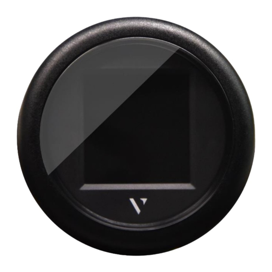
INTRODUCTION INTRODUCTION PACKAGING CONTENT 1x VL Flex 52 Industrial 1x 8-pole cable B00086001 A2C59512947 1x 52 mm Mounting Spinlock 1x Safety instructions A2C5205947101 B000100 THE ALL-IN-ONE INSTRUMENT The VL Flex device can easily be configured to be the it possible for the VL Flex to read from the digital networks as instrument you need - thanks to its sun-readable 1.44”... -
Page 4: Safety Instructions
• classified commercial shipping. Modifications or manipulations to veratron products can • Use our product only as intended. Use of the product for affect safety. Consequently, you may not modify or... - Page 5 SAFETY INSTRUCTIONS • The cables in use must have enough insulation and electric Use only the multimeter or diode test lamps provided, to strength and the contact points must be safe from touch. measure voltages and currents in the vehicle/machine or •...
- Page 6 INSTALLATION INSTALLATION WARNING Before beginning, disconnect the negative terminal on the battery, otherwise you risk a short circuit. If the vehicle is supplied by auxiliary batteries, you must also disconnect the negative terminals on these batteries! Short circuits can cause fires, battery explosions and damages to other electronic systems. Please note that when you disconnect the battery, all volatile electronic memories lose their input values and must be reprogrammed.
- Page 7 INSTALLATION INSTALLATION WITH SPINNLOCK Conventional assembly. (Instrument is put into the drill hole from the front). The panel width may be within a range of 0.5 to 20 mm. The drill hole must have a diameter of 53 mm [B]. WARNING •...
- Page 8 INSTALLATION FLUSH MOUNTING The recommended panel thickness is 1.5 to 3 mm. The drill hole must have a diameter of 48.1 mm. [A] Ensure that the installation location is level and has no sharp edges. WARNING • Do not drill holes or ports in load-bearing or stabilizing stays or tie bars! •...
-
Page 9: Connections
CONNECTIONS CONNECTIONS PINOUT Pin No. Wire Colour Description KL. 15 – Ignition Plus 12 / 24 V Black KL. 31 – GND Black / Blue Frequency input Brown Resistive input Green Intelligent Battery Sensor (LIN bus 2.0) Blue / Red Illumination Day/Night Yellow / Black SAE J1939 CAN bus High... - Page 10 CONNECTIONS SAE J1939 is a CAN bus (Data connection) that is often It’s important, that there is a so-called terminating used in motors or machines. It gets applied to connect all resistor connecting the ends of the two wires in the the different electrical components (sensors, displays, …) physical build up.
-
Page 11: Configuration
CONFIGURATION CONFIGURATION VL FLEX CONFIGURATOR APP In order to configurate the VL Flex 52 Industrial, one must set a A simple but detailed explanation of the configuration couple of parameters, such as display layout, the selected procedure can also be found on the app as an in-app- sensor and its calibration or the alarm threshold. - Page 12 CONFIGURATIONS SYSTEM CONFIGURATION 1. READ THE VL FLEX CONFIGURATION Launch the “VL Flex Industrial App” and read the actual configuration of the device by “tapping* the smartphone onto the front lens. The READ operation is mandatory before the WRITE operation is allowed. After the readout, the App will be set with the current VL Flex configuration.
- Page 13 CONFIGURATIONS Note: You can find the complete list of supported datatypes in the table “Supported Configurations” in this document. 4. SELECT UNIT AND INSTANCE Define the unit for the displayed data if there is more than one available. (See table “Supported Configurations”) Set the instance for the displayed data (e.g.
- Page 14 CONFIGURATIONS 6. CONFIGURE AN ALARM For many data types, an alarm can be added. (see table “Supported Configurations”) The alarm can be activated or deactivated with the switch in the according part of the section. As soon as the alarm is set as active, you can define at which point it should be triggered in the field next to the switch.
- Page 15 CONFIGURATIONS 8. SET ILLUMINATION BRIGHTNESS AND CLOCK The last few configurations can be found in the register “settings”. In this section you can set the display brightness for the day- and night mode by moving the sliders. Here you can also manage the clock setting. Note: The clock can only receive the time for the clock over the J1939 interface (and only if there is some kind of clock connected to your network).
- Page 16 CONFIGURATIONS SUPPORTED CONFIGURATIONS * Resistive Frequency Alarm J1939 Gauge Type Unit Symbol Calibration input input available Engine Speed Pulses per revolution ✔ (above) Wheel Based Speed SPEED Pulses per unit ✔ Net Battery Current Electrical Potential Battery SOC (below) Battery SOH (below) Battery °C...
- Page 17 CONFIGURATIONS Resistive Frequency Alarm J1939 Gauge Type Unit Symbol Calibration input input available 0 – 90 Ω 3 – 180 Ω 240 – 33 Ω Fuel Level ✔ (below) 90 – 4 Ω 105 – 4 Ω 291 – 22 Ω (120 °C) Engine Coolant °C ✔...
- Page 18 CONFIGURATIONS Resistive Frequency Alarm J1939 Gauge Type Unit Symbol Calibration input input available l/100km Instantaneous Fuel mpg (US) FUEL Economy mpg (UK) ECON. mpl (UK) Odometer 10 – 184 Ω (10 bar) Brake Pressure The values of the data types, that can neither be received over the resistive input nor over the frequency input, need to be transmitted on a digital way.
-
Page 19: Display Layout
DISPLAY LAYOUT DISPLAY LAYOUT NORMAL OPERATION Single layout Symbol Indicates, which data type is displayed right now. For the data types, which support this function, there is also the instance indicated here. Unit Shows the unit of the currently displayed data. For some data types it’s possible to change the unit in the settings. - Page 20 DISPLAY LAYOUT ALARM DISPLAY Single-data layout Dual data layout When an alarm occurs the bar-graph turns red When an alarm occurs on any of the two and a red alarm symbol is displayed in the top displayed data, the numeric digits of the part of the display between the data symbol and affected data become red.
-
Page 21: Technical Data
TECHNICAL DATA TECHNICAL DATA DATASHEET Display 1.44” sun-readable color TFT display, transmissive Resolution 125 x 125 Pixels Nominal Voltage 12 V / 24 V Operating Voltage 8 – 32 V with overvoltage and reverse polarity protection Current consumption Typ. 50 mA with maximum backlight intensity Resistive (0 –... -
Page 22: Accessories
Bezel – Flat Chrome* A2C5318602301 Visit http://www.veratron.com for the complete list of accessories. * the chrome bezel might interfere with the NFC programming due to the metallic particles contained in the chrome material. Make sure to configure the VL Flex device BEFORE installing the chrome bezel! - Page 23 AG, except for the following actions: • Printing the document in its original format, totally or partially. • Copying contents without any modifications and stating Veratron AG as copyright owner. Veratron AG reserves the right to make modifications or improvements to the relative documentation without notice.
Need help?
Do you have a question about the VL FLEX 52 INDUSTRIAL and is the answer not in the manual?
Questions and answers