
Related Manuals for York MCH CRAH


Summary of Contents for York MCH CRAH
- Page 1 MCH CRAH™ Air Handling Units Installation and Assembly Supersedes: CRAH102.20-N1 (1223) Form: CRAH102.20-N1 (324) Mission Critical Horizontal Computer Room Air Handler MCH CRAH Issue Date: March 11, 2024...
- Page 2 Form CRAH102.20-N1 Issue date: 03/11/2024 Important Read before proceeding General safety guidelines This equipment is a relatively complicated apparatus. is expected that these individuals possess independent During rigging, installation, operation, maintenance, or training that will enable them to perform their assigned service, individuals may be exposed to certain compo- tasks correctly and safely.
- Page 3 Description 33 to 37 Added the Condensate pump section. Associated literature Manual description Form number YORK Air Handling Units Operation and Maintenance 102.20-OM2 Steps to Protect New Equipment Warranty 102.20-CL1 Air Handling Units Start-up Checklist 100.00-CL1 CRAH AHU Start-Up Checklist CRAH102.20-CL1...
-
Page 4: Table Of Contents
Form CRAH102.20-N1 Issue date: 03/11/2024 Table of contents SECTION 1 - GENERAL INFORMATION AND SAFETY ..................7 Introduction ............................... 7 Warranty ................................7 Responsibility for safety ........................... 7 Safe entry procedure ............................8 SECTION 2 - PRODUCT DESCRIPTION ......................9 CRAH identification (ID) ........................... 9 AHU ID label ............................9 General electrical information ........................ - Page 5 Form CRAH102.20-N1 Issue date: 03/11/2024 Table of contents, continued Condensate pump ............................33 Pump description and specifications ..................... 33 Factory-provided pump location and installation ................... 34 Field connections and removal of pump ....................35 Removing and gaining access to the pump ..................35 Field optional condensate pump installation ..................
- Page 6 Form CRAH102.20-N1 Issue date: 03/11/2024 This page intentionally left blank. Johnson Controls...
-
Page 7: Section 1 - General Information And Safety
• Contains detailed procedures, including installa- ing conditions must be satisfied: tion, commissioning and maintenance tasks that must only be performed by suitably trained and • Only genuine YORK approved spare parts must qualified personnel. be used. Read the manual thoroughly before attempting to oper- •... -
Page 8: Safe Entry Procedure
Form CRAH102.20-N1 Section 1 - General information and safety Issue date: 03/11/2024 Safe entry procedure Do not attempt any installation or maintenance work on the electrical equipment without first switching incoming power off, and isolating and locking-off the power supply according to the appropriate Johnson Controls service manuals. -
Page 9: Section 2 - Product Description
Form CRAH102.20-N1 Issue date: 03/11/2024 Section 2 - Product description Coil connections and other components are located and described as left or right hand. The correct orientation to describe the correct hand is when airflow is at your back. CRAH identification (ID) AHUs are labeled with the following ID labels: •... -
Page 10: General Electrical Information
Form CRAH102.20-N1 Section 2 - Product description Issue date: 03/11/2024 General electrical information To set up the electrical connections: complete the fol- All field wiring must conform to the lowing steps: International Building Codes (IBC), National Electrical Code (NEC) and 1. -
Page 11: Section 3 - Handling, Storage, And Installation
Form CRAH102.20-N1 Issue date: 03/11/2024 Section 3 - Handling, storage, and installation Delivery and storage To ensure consistent quality and maximum reliability, all AHUs are tested and inspected before leaving the factory. LD19197 Figure 2: Rigging warning Rigging and lifting must only be done by a professional rigger in accordance with a written rigging and lifting plan. -
Page 12: Correct Lifting With Shackles
Form CRAH102.20-N1 Section 3 - Handling, storage, and installation Issue date: 03/11/2024 Correct lifting with shackles • Maximum system design water pressure: 130 psi Fasten shackles to a sling or chain and use them to safely lift and lower the sections of a tiered AHU. Re- •... - Page 13 Form CRAH102.20-N1 Section 3 - Handling, storage, and installation Issue date: 03/11/2024 LD32736 LD32 Figure 5: Base rail installation for forklift Figure 6: Base rails as shipped Install the base rails after the units are You can use a top strap when trucking in place, when they will no longer be CRAH units.
-
Page 14: Short-Term Storage
Form CRAH102.20-N1 Section 3 - Handling, storage, and installation Issue date: 03/11/2024 LD32754 LD32753 Callout Part number Callout Part number 086-52188-755 086-52188-755 086-52188-754 086-52188-754 086-52188-756 086-52188-756 Figure 7: Front and rear side base rail part numbers Short-term storage • Decontaminate or replace parts as needed to make Short-term storage is six months or less from the date sure microbial growth is not introduced to the of shipment. -
Page 15: Short-Term Storage Of Ebm-Pabst And Ziehl-Abegg Ecm Fans
Form CRAH102.20-N1 Section 3 - Handling, storage, and installation Issue date: 03/11/2024 Short-term storage of EBM-Pabst and Ziehl- Abegg ECM fans • Store the device, partially or fully assembled, in a • Avoid prolonged storage. We recommend a maxi- dry and weatherproof manner in the original pack- mum of one year. -
Page 16: Receiver's Responsibility
Form CRAH102.20-N1 Section 3 - Handling, storage, and installation Issue date: 03/11/2024 Failure to fulfill the long term storage Preventive maintenance prior to long term requirements will void the warranty. storage Take the following precautions before extended stor- age: • Protect the motors and sheaves from free moisture or high humidity, which may be accomplished by: Receiver's responsibility •... -
Page 17: Unit Configuration
Form CRAH102.20-N1 Section 3 - Handling, storage, and installation Issue date: 03/11/2024 Unit configuration Figure 8: Configuration of units with 15K CFM (2,534 lb) air flow Figure 9: Configuration of units with 30K CFM (3,836 lb) air flow Johnson Controls... -
Page 18: Installation
Form CRAH102.20-N1 Section 3 - Handling, storage, and installation Issue date: 03/11/2024 Figure 10: Configuration of units with 45K CFM (4,683 lb) air flow Weight may vary depending on unit Installation selection, however, the weights listed are Leveling the unit the heaviest configuration. - Page 19 Form CRAH102.20-N1 Section 3 - Handling, storage, and installation Issue date: 03/11/2024 Figure 11: Configuration of units with 60K CFM air flow (4400 lower segment and 2200 upper segment) Johnson Controls...
-
Page 20: Installing The Gruvlok® Rubber Grommet
Form CRAH102.20-N1 Section 3 - Handling, storage, and installation Issue date: 03/11/2024 Installing the Gruvlok® rubber grommet This is a critical point connection step. Important: The following figure shows the final assembly with segments secured, piping aligned, and the grommet Before the top segment is assembled, remove the pip- moved up over the seam. -
Page 21: Victaulic® Fittings
Form CRAH102.20-N1 Section 3 - Handling, storage, and installation Issue date: 03/11/2024 Victaulic® fittings CRAH units are changing from Gruvlok brand couplings to the Victaulic brand couplings for the header body of FWC coils. Installers must inspect the fittings to verify what brand they have. -
Page 22: Dimensions
Form CRAH102.20-N1 Section 3 - Handling, storage, and installation Issue date: 03/11/2024 Dimensions Figure 16: Pre-assembled, installation-ready Figure 17: Joint assembled condition Table 7: Dimensions for style 107V Victaulic QuickVic couplings Pipe end Size Bolt/nut Dimensions Weight separation Pre-assembled, Actual installation-ready Joint assembled Nominal... -
Page 23: Ansi Standards
Form CRAH102.20-N1 Section 3 - Handling, storage, and installation Issue date: 03/11/2024 ANSI standards Table 8: ANSI standards for style 107V Victaulic QuickVic couplings Size Schedule 10 Standard weight (STD) Nominal Actual Wall Maximum Maximum Wall Maximum Maximum inches (DN) outside thickness, joint working... -
Page 24: Crah Pull Through High Voltage Box
Form CRAH102.20-N1 Section 3 - Handling, storage, and installation Issue date: 03/11/2024 CRAH pull through high voltage box All CRAH units built from 12/2023 to The field is required to use this pull through box and present date have the push-pull fuse conduit to reach the high voltage terminals in the ABB terminal block removed and a factory disconnect or ATS. -
Page 25: Field Installed Piping
Form CRAH102.20-N1 Section 3 - Handling, storage, and installation Issue date: 03/11/2024 Field installed piping Piping can shift during shipping. If necessary, the field user can adjust the vertical piping brackets using the slotted screws and added holes to achieve alignment. See Figure 20 on page 25. -
Page 26: Field Connections
Form CRAH102.20-N1 Section 3 - Handling, storage, and installation Issue date: 03/11/2024 Field connections Callout Description Pipe connections High voltage power Vent Drain Condensate Figure 21: Field connections Johnson Controls... - Page 27 Form CRAH102.20-N1 Section 3 - Handling, storage, and installation Issue date: 03/11/2024 Note: If the condensate pump is field-provided and installed in the field, see Figure 22, Figure 23 and Figure 24 on page 27. Figure 22: Side cut out view showing a right-handed unit (left-handed is on the opposite side) Figure 23: Front view (left-handed) Figure 24: Front view with bottom base (field-installed cover plate added) Johnson Controls...
-
Page 28: Filters
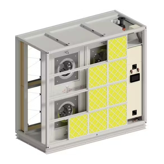
Form CRAH102.20-N1 Section 3 - Handling, storage, and installation Issue date: 03/11/2024 Filters Depending on the size of the ordered filter track, the following options are available: • 2 in. pleated 24 W x 24 H MERV 11 (P/N 026 32406 903) •... -
Page 29: Upper Segment Assembly
Form CRAH102.20-N1 Section 3 - Handling, storage, and installation Issue date: 03/11/2024 Upper segment assembly Remove the discharge grate from The discharge grate from the top tier unit is installed to the top of the bottom unit for shipment. Remove and the top of the lower segment before installing the top segment into position. - Page 30 Form CRAH102.20-N1 Section 3 - Handling, storage, and installation Issue date: 03/11/2024 Figure 31: Gasket installation (2) Callout Description Install the gasket 1.8 in. thick x 2.25 in. wide (Part No. 028-11882-010) to the top surface of the raceways around the entire perimeter of the unit Top tier to bottom tier pipe coupling connect (Part No.
-
Page 31: Multiple Single Flat Plate For Top/Bottom Segment Field Assembly
Form CRAH102.20-N1 Section 3 - Handling, storage, and installation Issue date: 03/11/2024 Ensure that the neoprene gasket is Multiple single flat plate for top/bottom correctly installed on the bottom tier. segment field assembly Note: The top tier is shipped with the angled style of brackets for shipping purposes. -
Page 32: Top Segment Signal Wiring
Form CRAH102.20-N1 Section 3 - Handling, storage, and installation Issue date: 03/11/2024 Top segment signal wiring Callout Description ATS wiring runs across the front raceway and along the DOA raceway with coil vent piping Valve wiring runs through bushing at the top of internal electrical wall, then along internal panels over to the valve location. -
Page 33: Condensate Pump
Form CRAH102.20-N1 Section 3 - Handling, storage, and installation Issue date: 03/11/2024 Condensate pump • Additional check valve adapter included for A factory-installed condensate pump, the Little Giant VCCA-20ULS Series pump, is available as an option. 1/4 in. ID vinyl tubing •... -
Page 34: Factory-Provided Pump Location And Installation
Form CRAH102.20-N1 Section 3 - Handling, storage, and installation Issue date: 03/11/2024 The following figure shows the performance data for Factory-provided pump location and VCCA-20ULS/VCCA-20-P condensate pump (155 V installation and 230 V, 60 Hz). The condensate pump is factory-installed and piped to the top area of the lower segment header piping area. -
Page 35: Field Connections And Removal Of Pump
Form CRAH102.20-N1 Section 3 - Handling, storage, and installation Issue date: 03/11/2024 Field connections and removal of pump As noted previously, the pump is already installed and piped. The field is only required to complete the fol- lowing steps: 1. Plug the pump into the AHU’s 120 V outlet located above the pump. -
Page 36: Field Optional Condensate Pump Installation
Form CRAH102.20-N1 Section 3 - Handling, storage, and installation Issue date: 03/11/2024 Detail BB Detail BC Figure 45: Condensate pump tray removal Field optional condensate pump installation The field-provided condensate pump must adhere to the available space in the pump location shown in the following figure. - Page 37 Form CRAH102.20-N1 Section 3 - Handling, storage, and installation Issue date: 03/11/2024 Detail BB Detail BC Callout Description Electrical cabinet back plate Pump drain connection 3/4 in. barb fitting Tubing plastic, 0.63 ID x 0.813 OD 90° fitting sits in the drain port of the pump. The fitting does not thread in. 3/8 in.
-
Page 38: Chilled Water System
Form CRAH102.20-N1 Section 3 - Handling, storage, and installation Issue date: 03/11/2024 Chilled water system Table 12: Technical description Specification Value Check all of the water piping for correct strain relief. Weight 27.8 kg Ensure that you carry out the following procedures on Fan size 560 mm the evaporator water piping:... -
Page 39: Ebm-Pabst Power-Signal Connector
Form CRAH102.20-N1 Section 3 - Handling, storage, and installation Issue date: 03/11/2024 Table 11: Technical description, continued Specification Value Touch current <= 3.5 mA according to IEC 60990 (measuring circuit Fig.4, TN system) Electrical hookup Via terminal box Motor protection Reverse polarity and locked-rotor protection Protection class... -
Page 40: Controller/Points List
Form CRAH102.20-N1 Section 3 - Handling, storage, and installation Issue date: 03/11/2024 Controller/Points list Figure 49: SNC Network Control Engine (m4-SNC2510-X) Table 13: SNC base features Product code number Description Supervisory Network Control Engine Series Every SNC model includes the following functionality: •... -
Page 41: Section 4 - Operating The Hmi Touch Screen
Navigate to HMI screens by using the navigation but- tons in the lower bar of the display. Access the naviga- tion menu can by tapping either the YORK or Johnson Controls icons in the bottom corners of the display. Figure 50: Lower bar of the display... -
Page 42: Unit Graphic Settings
Form CRAH102.20-N1 Section 4 - Operating the HMI touch screen Issue date: 03/11/2024 All users can view operational information displayed Unit graphic settings on the HMI Main screen but no one can write. Service CRAH unit Shutdown/Enable Control, Filter Alarm and Admin can change the date on any screen. -
Page 43: Trends
Form CRAH102.20-N1 Section 4 - Operating the HMI touch screen Issue date: 03/11/2024 Figure 55: Unit graphic with flyouts Trends CRAH unit Trend Data is displayed on the HMI Trend 24 hour trending data, a data log, is available on the screens. -
Page 44: Alarms
Filters changed, Faulted Figure 57: Alarm screen Service Tap the lower left YORK/Johnson Controls icons on cluding enabling the system. Service and Admin can the screen to adjust the settings for the entire unit, in- view this screen and write to any field in blue. -
Page 45: Section 5 - Technical Data
Form CRAH102.20-N1 Issue date: 03/11/2024 Section 5 - Technical data Valves technical data The technical data for valves P6250SU-127, P6300SU-180, P6400SU-317 are as follows. P6250SU-127 technical data Table 16: Valve P6250SU-127 technical data Specification Value Specification Value Fluid Chilled or hot water, up to 60% Ambient temperature -22°F to 122°F (-30°C to 50°C) glycol max (open loop /steam not... -
Page 46: P6300Su-180 Technical Data
Form CRAH102.20-N1 Section 5 - Technical data Issue date: 03/11/2024 P6300SU-180 technical data Table 17: Valve P6300SU-180 technical data Specification Value Specification Value Fluid Chilled or hot water, up to 60% Ambient temperature -22°F to 122°F (-30°C to 50°C) glycol max (open loop /steam not Inlet length to 5X nominal pipe size (NPS) allowed) -
Page 47: P6400Su-317 Technical Data
Form CRAH102.20-N1 Section 5 - Technical data Issue date: 03/11/2024 P6400SU-317 technical data Table 18: Valve P6400SU-317 technical data Data Specification Value Electrical data Nominal voltage AC/DC 24 V Nominal voltage frequency 50/60 Hz Nominal voltage range AC 19.2 V to 28.8 V / DC 21.6 V to 28.8 V Power consumption in operation 9.5 W Transformer sizing... - Page 48 Form CRAH102.20-N1 Section 5 - Technical data Issue date: 03/11/2024 P6400SU-317 technical data (continued) Table 18: Valve P6400SU-317 technical data (continued) Data Specification Value Flow measurement Measuring accuracy flow ±2% Measurement repeatability ±0.5% (flow) Sensor technology Ultrasonic with glycol and temperature compensation Safety data Power source UL Class 2 supply...
-
Page 49: Akrx24-Ep2 Technical Data
Form CRAH102.20-N1 Section 5 - Technical data Issue date: 03/11/2024 AKRX24-EP2 technical data Johnson Controls... - Page 50 Form CRAH102.20-N1 Section 5 - Technical data Issue date: 03/11/2024 AKRX24-EP2 technical data (continued) Table 19: AKRX24-EP2 technical data Specification Value Specification Value Power supply 24 VAC, ±20%, 50/60 Hz, 24 Manual override External push button VDC, -10% / +20% Running time (motor) 90 s Power consumption in...
-
Page 51: Automatic Transfer Switch
Form CRAH102.20-N1 Section 5 - Technical data Issue date: 03/11/2024 Automatic transfer switch Figure 59: Automatic transfer switch/panel CRAH wiring NOTES: 1. ALL DIMENSIONS SHOWN IN INCHES 2. UL TYPE 1 13.10 3. TOP ENTRY/BOTTOM EXIT 4. APPROXIMATE WEIGHT 340 LBS. 10.75"... - Page 52 Form CRAH102.20-N1 Section 5 - Technical data Issue date: 03/11/2024 CRAH wiring (continued) 18.00 12.00 16.50 3.00 17.00 17.00 10.75 Ø0.875" 2.00 SOURCE 1 CAUTION VOLTAGE MAY BE PRESENT FROM MORE THAN ONE SOURCE AND SHOULD BE DISCONNECTED FOR SERVICING. ATTENTION PEUT ETRE SOUS TENSION DE PLUS D'UNE SOURCE D'ALIMENT ELECTRIQUE.
- Page 53 Form CRAH102.20-N1 Section 5 - Technical data Issue date: 03/11/2024 CRAH wiring (continued) 16.20 PWS2 100VA 15.20 PWS1 INPUT OUTPUT 16.20 SOLA HD UPS MOUNTED ON CABINET DOOR SOURCE 1 55.20 T1 LOCATED 250VA UNDER HAT BRACKET Ø0.156 6.3-10A 6.3-10.0A 6.3-10A 6.3-10.0A 6.3-10.0A...
-
Page 54: Wiring Diagram With Ats Dual Power Disconnect
Form CRAH102.20-N1 Section 5 - Technical data Issue date: 03/11/2024 Wiring diagram with ATS dual power disconnect Notes Description Notes Description Programming: per customer request. Refer to the user's manual for I/O ratings. Refer to the user manual for operation, connections Short circuit current rating 100KA RMS symmetrical, for and tightening torque values. - Page 55 Form CRAH102.20-N1 Section 5 - Technical data Issue date: 03/11/2024 Johnson Controls...
- Page 56 Form CRAH102.20-N1 Section 5 - Technical data Issue date: 03/11/2024 Table 20: BOM layout Quantity Tags Part number Manufacturer Description 3AUA294001B169 CAUTION LABEL DECAL, WAIT AFTER DISCONNECTING C-106-2PM ZINC/STEEL DIN RAIL EN 50022 (35mm x 7.5mm x 2m) CL2-513G PILOT LIGHT, GREEN, 120 VAC LED, 22mm CL2-513L PILOT LIGHT, BLUE, 120 VAC LED, 22mm LABEL-CAUTION...
- Page 57 Form CRAH102.20-N1 Section 5 - Technical data Issue date: 03/11/2024 Table 20: BOM layout (continued) Quantity Tags Part number Manufacturer Description 1SNK 506 210 R0000 ENTRELEC TERMINAL BLOCK DUAL - ZS6, 6mm, GREY 1SNK 900 001 R0000 ENTRELEC END STOP - BAM3 AFM-120B GARDTEC MESH FAN GRILL, 4"...
-
Page 58: Crah Points List, Wiring Diagram
Form CRAH102.20-N1 Section 5 - Technical data Issue date: 03/11/2024 CRAH points list, wiring diagram The points list applies to units sized 15K to 60K. Controller or Terminations Point Type Object Name Expanded ID Device Location Comment Wire Color Terminal Block BLACK Power to Controller BacNet FC Bus... - Page 59 Form CRAH102.20-N1 Section 5 - Technical data Issue date: 03/11/2024 Johnson Controls...
-
Page 60: Wiring Diagram Disconnect Only
Form CRAH102.20-N1 Section 5 - Technical data Issue date: 03/11/2024 Wiring diagram disconnect only Notes Description Notes Description Programming: per customer request. Use copper conductors only. 75°C (167°F) rated or higher; terminations rated for 75°C (167°F). Refer to the user manual for operation, connections and tightening torque values. - Page 61 Form CRAH102.20-N1 Section 5 - Technical data Issue date: 03/11/2024 Johnson Controls...
- Page 62 Form CRAH102.20-N1 Section 5 - Technical data Issue date: 03/11/2024 Johnson Controls...
- Page 63 Form CRAH102.20-N1 Section 5 - Technical data Issue date: 03/11/2024 Johnson Controls...
- Page 64 Form CRAH102.20-N1 Section 5 - Technical data Issue date: 03/11/2024 Table 21: BOM layout Quantity Tags Part number Manufacturer Description 3AUA294001B169 CAUTION LABEL DECAL, WAIT AFTER DISCONNECTING 3AUA294001B194 ABB LOGO DECAL C-106-2PM ZINC/STEEL DIN RAIL EN 50022 (35mm x 7.5mm x 2m) LABEL-CAUTION CAUTION LABEL DECAL LABEL-WARNING...
- Page 65 Form CRAH102.20-N1 Section 5 - Technical data Issue date: 03/11/2024 Table 21: BOM layout (continued) Quantity Tags Part number Manufacturer Description MCSBK-627 HAT BRACKET, 7 X 14.2 X 6" TALL, MMP ATS HAT BRACKET MCSEN-741812N1- ENCLOSURE, 741812, N1, ANSI-61 GREY MIRUS-ANSI-61 MCSPL-651 COVER PLATE, OHBXXX HANDLE PLATE...
-
Page 66: Renewable Parts List
Form CRAH102.20-N1 Section 5 - Technical data Issue date: 03/11/2024 Renewable parts list Table 22: Valve part numbers Part number Part Max design GPM 022 14318 200 2 in. 2-way CCV 022 14318 250 2.5 in. 2-way CCV 022 14318 300 3 in. - Page 67 Form CRAH102.20-N1 Section 5 - Technical data Issue date: 03/11/2024 Table 22: Valve part numbers (continued) Part number Part Max design GPM 022 14305 308 3 in. 2-way EPIV15LH5LH 022 14305 309 3 in. 2-way EPIV160LH 022 14305 310 3 in. 2-way EPIV165LH 022 14305 311 3 in.
- Page 68 Form CRAH102.20-N1 Section 5 - Technical data Issue date: 03/11/2024 Table 23: Fan part numbers Part number Part 026 50040 501 Ebm_560_460v_3ph_4.5kw, 6.0 Fla 026 50040 502 Ebm_560_460v_3ph_4.5kw, 5.4 Fla 026 50040 504 Ebm_560_460v_3ph_4.5kw, 3.6 Fla Table 24: Touch panel part numbers Part number Part 025 53383 001...
- Page 69 Form CRAH102.20-N1 Issue date: 03/11/2024 The following factors can be used to convert from English to the most common SI Metric values. Table 31: SI Metric Conversion Measurement Multiply English unit By factor To obtain metric unit Capacity Tons refrigerant effect (ton) 3.516 Kilowatts (kW) Power...
- Page 70 5000 Renaissance Drive, Pennsylvania USA,17439 1-800-524-1330 Subject to change without notice. Printed in USA Copyright © by Johnson Controls 2024 www.johnsoncontrols.com All rights reserved Form CRAH102.20-N1 (324) Issue Date: 11 March 2024 Supersedes: CRAH102.20-N1 (1223)
Need help?
Do you have a question about the MCH CRAH and is the answer not in the manual?
Questions and answers