
Related Manuals for York AHU


Summary of Contents for York AHU
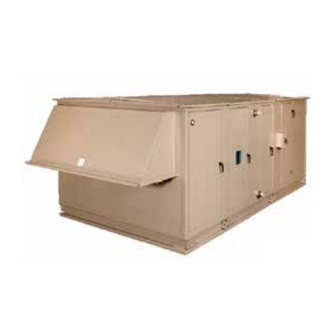
- Page 1 AIR HANDLING UNITS OPERATION AND MAINTENANCE New Release Form 102.20-OM2 (615) LD09624 LD17323 INDOOR SOLUTION XT AHU OUTDOOR SOLUTION XT AHU LD13282 YORK CUSTOM AHU Issue Date: June 1, 2015...
- Page 2 FORM 102.20-OM2 ISSUE DATE: 6/01/2015 IMPORTANT! READ BEFORE PROCEEDING! GENERAL SAFETY GUIDELINES This equipment is a relatively complicated apparatus. which it is situated, as well as severe personal injury or During rigging, installation, operation, maintenance, death to themselves and people at the site. or service, individuals may be exposed to certain com- This document is intended for use by owner-authorized ponents or conditions including, but not limited to:...
- Page 3 If there is any ques- ASSOCIATED LITERATURE MANUAL DESCRIPTION FORM NUMBER Solution XT Air Handling Units Installation and Assembly 102.20-N1 York Custom Air Handling Units Installation and Assembly 102.20-N3 Steps to Protect New Equipment Warranty 102.20-CL1 Air Handling Units Start-up Checklist 100.00-CL1 Long-Term Storage Requirement - Field Preparation - Air Handling Units 50.20-NM3...
- Page 4 FORM 102.20-OM2 ISSUE DATE: 6/01/2015 SOLUTION XT UNIT MODEL NOMENCLATURE 048 x VOLTAGE CODE 12=120-1-60 17=200 or 208-3-60 NOMINAL NOMINAL FACTORY MOUNTED 27=277-1-60 HEIGHT WIDTH END DEVICES 27 to 132 27 to 288 28=230 or 240-3-60 0=No 40=360-3-60 1=Yes 44=440-3-50 ENVIRONMENT 46=460-3-60 I=Indoor...
-
Page 5: Table Of Contents
FORM 102.20-OM2 ISSUE DATE: 6/01/2015 TABLE OF CONTENTS SECTION 1 - GENERAL INFORMATION AND SAFETY ..................13 Introduction ..............................13 About This Manual............................13 Warranty ................................. 13 Responsibility For Safety ..........................13 SECTION 2 - START-UP AND OPERATION ......................15 Before Start-Up .............................. 15 Inspecting Fan Assembly ........................16 Inspecting Belts and Sheaves ....................... - Page 6 FORM 102.20-OM2 ISSUE DATE: 6/01/2015 TABLE OF CONTENTS (CONT'D) Checking Condition of Extended Lubrication Lines ................61 Recommended Lubricant for Bearings ....................61 Proper Interval and Quantity ......................... 61 Lubricating the Fan Segment and Motor ......................62 Checking Condition of Mounting Hardware, Adjustable Motor Base and Motor ........63 Checking Electrical Connections ......................
- Page 7 FORM 102.20-OM2 ISSUE DATE: 6/01/2015 TABLE OF CONTENTS (CONT'D) SECTION 4 - SERVICE AND REPAIR ........................77 Service Tools and Equipment ......................... 77 Service Information ............................78 Troubleshooting .............................. 78 Pitot Tube ............................... 78 Inclined Manometer ............................79 Filter Gauge ..............................79 U-Tube Manometer ............................
- Page 8 FIGURE 19 - Example of Sweep Balance Results Label On Fan Housing ............. 29 FIGURE 20 - Metal Spacers on Solution XT Doors ....................29 FIGURE 21 - Vertical Wheel for Indoor AHU ......................29 FIGURE 22 - Horizontal Wheel for Outdoor AHU ....................30 FIGURE 23 - Energy Recovery Wheel - Pulley Side ....................31...
- Page 9 FORM 102.20-OM2 ISSUE DATE: 6/01/2015 LIST OF FIGURES (CONT'D) FIGURE 48 - Alignment Using Straight Edge ......................58 FIGURE 49 - Alignment Using String ........................58 FIGURE 50 - Sheave Angular Misalignment ......................59 FIGURE 51 - Motor Base Lowered..........................59 FIGURE 52 - Sheave Angular Alignment.........................59 FIGURE 53 - Sheave Angular Misalignment ......................60 FIGURE 54 - Sealed Bearing ..........................60 FIGURE 55 - Bearing with Set Screw Type Locking Device ...................60...
- Page 10 FORM 102.20-OM2 ISSUE DATE: 6/01/2015 LIST OF FIGURES (CONT'D) FIGURE 95 - Outside Air Damper Kit (Relay Installation) ..................92 FIGURE 96 - Solution XT Termination Chart Inside Enclosure Door ..............93 FIGURE 97 - Typical FPC Wiring Diagram ......................94 FIGURE 98 - Transformer Enclosure Wiring Detail (Shown Open) .................96 FIGURE 99 - Transformer Wiring Diagram......................97 FIGURE 100 - UV Control Panel Wiring (8 amps)....................99 FIGURE 101 - UV Control Panel Wiring ( greater than 8 amps) ................100...
- Page 11 FORM 102.20-OM2 ISSUE DATE: 6/01/2015 LIST OF TABLES TABLE 1 - Torque for Tightening Set Screws ......................16 TABLE 2 - Air Measuring Device Connections ......................21 TABLE 3 - Indoor Unit Example ..........................27 TABLE 4 - Outdoor Unit Example ...........................28 TABLE 5 - Gas Heat Segment Model Number Nomenclature ................39 TABLE 6 - Natural Gas Pressure Requirements (Inches Wc) ................40 TABLE 7 - Natural Gas Pressure Requirements (Inches Wc) ................41 TABLE 8 - Inlet Size (NPT) .............................42...
- Page 12 FORM 102.20-OM2 ISSUE DATE: 6/01/2015 SERVICE TASK REFERENCE Adjustable Motor Base Energy Recovery Wheel Operation Control Wiring Start-Up Air Louvers Inspection External Lube Lines Air Modulator Fan Assembly Start-Up Pre Start-Up Inspection Cleaning Belts Maintenance Inspection Checking Tension Fan Bearing Bird Screen Types Inspection...
-
Page 13: Section 1 - General Information And Safety
The AHU warranty will be void if any modification to regulations. the AHU is carried out without prior written approval • Contains all the information required for correct from Johnson Controls. - Page 14 FORM 102.20-OM2 SECTION 1 - GENERAL INFORMATION AND SAFETY ISSUE DATE: 6/01/2015 THIS PAGE INTENTIONALLY LEFT BLANK. JOHNSON CONTROLS...
-
Page 15: Section 2 - Start-Up And Operation
Variable Frequency Drive (VFD), re- fer to the specific VFD literature for additional start-up requirements. • Check for damage to the AHU's interior and ex- terior. • Ensure the terminal screws and wiring connec- tions are secure in the control, electric and air modulator panels. -
Page 16: Inspecting Fan Assembly
MINIMUM RECOMMEND- bly. SETSCREW ACROSS ED TORQUE DIAMETER FLATS (IN) 1. When the AHU is removed from long term stor- (IN) IN LB FT LB age, purge the moisture-laden bearing grease, and 66 - 85 5.5 - 7.08 replenish the AHU with fresh grease, according to... -
Page 17: Inspecting Belts And Sheaves
Tighten the cap screws. Refer to the ser- SUPPORT FRAME vice manual for additional instructions. • Verify the fan is aligned with the AHU discharge. Inspecting Belts and Sheaves • Readjust the isolators as necessary. 1. Verify that the sheaves are properly aligned and tight on the shaft. -
Page 18: Figure 5 - Spring Isolator Set-Up
FORM 102.20-OM2 SECTION 2 - START-UP AND OPERATION ISSUE DATE: 6/01/2015 Custom AHU Isolators Fan Hold-Down/Spring Isolator Set-Up All fans are internally spring isolated and will be bolt- Place tubes on studs, and place shoulder washer (shoul- ed down for unit shipping. After unit is in place, assem- der up) on studs. -
Page 19: Start-Up
The counterbalance should If the AHU is equipped with an energy recovery wheel, be free to rotate. rotate the wheel when the AHU is in service to prevent clogging. Checking Operation of Fans Check of the operation of the fans by: 1. -
Page 20: Figure 8 - Front Of A 2X2 Fan Array
Many combinations of damper sizes are available to control the flow. Mixing the return and outside air in the AHU's air inlet section may be supplied as follows: • 100% outside air, 100% return air. • 100% outside air, 0% return air. -
Page 21: Table 2 - Air Measuring Device Connections
FORM 102.20-OM2 SECTION 2 - START-UP AND OPERATION ISSUE DATE: 6/01/2015 TABLE 2 - AIR MEASURING DEVICE CONNECTIONS FAN SIZE FAN SIZE TYPE CLASS TYPE CLASS ATLI 3675.20 0.5064 EPFN 944.92 ATLI 3919.00 0.5534 EPFN 944.92 ATLI 5510.60 0.4857 EPFN 944.92 ATLI 10x7... - Page 22 FORM 102.20-OM2 SECTION 2 - START-UP AND OPERATION ISSUE DATE: 6/01/2015 TABLE 2 - AIR MEASURING DEVICE CONNECTIONS (CONT'D) FAN SIZE FAN SIZE TYPE CLASS TYPE CLASS ATZAF 20x20 5843.70 EPFN 16111.75 ATZAF 20x20 5301.10 EPLFN 944.92 ATZAF 22x22 7513.40 EPLFN 1206.40 ATZAF...
-
Page 23: Figure 11 - High And Low Connections For An In Fan Air Monitoring System
FORM 102.20-OM2 SECTION 2 - START-UP AND OPERATION ISSUE DATE: 6/01/2015 TABLE 2 - AIR MEASURING DEVICE CONNECTIONS (CONT'D) FAN SIZE FAN SIZE TYPE CLASS TYPE CLASS MPQS 5968.62 MPQN 5968.62 MPQS 5968.62 MPQN 5968.62 MPQS 5968.62 MPQN 7290.21 MPQS 7290.21 MPQN 7290.21... -
Page 24: Figure 12 - High And Low Connections And Associated Tubing For Fan Mounted Air Monitoring System
It is ideally suited for factory installation in air handling LD17232 units. The YORK AMS-60 is tested to AMCA Stan- FIGURE 12 - HIGH AND LOW CONNECTIONS AND ASSOCIATED TUBING FOR FAN MOUNTED AIR... -
Page 25: Figure 14 - Ductwork Inlet Requirements
FIGURE 17 - 25%/75% SENSING OPTION Outdoor AHU economizer and mixing box sections will utilize an integral rain resistant, airflow sensing louver/damper combination with operation and set-up similar to the AMS-60. The indoor and outdoor AHU designs have the same possible damper configurations. JOHNSON CONTROLS... -
Page 26: Figure 18 - 25%/75% Sensing Option
Upon loss of toring station is 300 FPM for the indoor AHU and 345 power, the AMS-60 actuator returns to a closed posi- FPM for the outdoor AHU. -
Page 27: Table 3 - Indoor Unit Example
If ASHRAE 90.1 is referenced, also include * This paragraph only applies if the actuator and trans- ducer are YORK supplied. Any controls provided by If airflow station is internally mounted inside air han- "others" are the contractor's responsibility. -
Page 28: Energize Fan Motors
Solution XT Air Handling Units - Installation and ly rotated to its proper position, manually operate Assembly Manual (Form 102.20-N1) and York Custom the actuator to its fully actuated position, using the Air Handling Units - Installation and Assembly Man- crank arm provided with the actuator. -
Page 29: Variable Frequency Drive (Vfd)
(Figure 20 on page 29). The spacers should start-up service. See forms 100.41-NO1 be left in place until the AHU is placed in its final loca- and 100.42-NO1. tion and multiple skid AHUs are fully assembled. After AHU installation use a channel lock pliers or a screw- driver to remove the spacers. -
Page 30: Figure 22 - Horizontal Wheel For Outdoor Ahu
Return Air O/A Damper Coil Coil LD09641a FIGURE 22 - HORIZONTAL WHEEL FOR OUTDOOR AHU When the AHU is operating normally or Many energy recovery wheels are sus- temporarily, the energy recovery wheel ceptible to damage if the AHU reaches a must rotate to prevent clogging. -
Page 31: Figure 23 - Energy Recovery Wheel - Pulley Side
ISSUE DATE: 6/01/2015 3. With hands and objects away from the moving Airxchange ® parts, activate the AHU, and confirm the wheel Start-Up Procedure rotation. The wheel rotates clockwise from the 1. With the power off, turn the wheel clockwise pulley side. -
Page 32: Figure 24 - Segment Retainer
FORM 102.20-OM2 SECTION 2 - START-UP AND OPERATION ISSUE DATE: 6/01/2015 Innergy tech ® Segment Retainer Catch Start-Up Procedure Rotate Away From 1. Make sure all bearing bolts and set screws are Wheel Rim tight. A special seal lacquer is factory applied. This is a visual aid that will warn you if the pillow block bolts or the bearings set screws have loos- Spoke... -
Page 33: Figure 26 - Purge Angle Detail
FORM 102.20-OM2 SECTION 2 - START-UP AND OPERATION ISSUE DATE: 6/01/2015 6. If the unit is supplied with an adjustable purge, Thermotech ® determine the proper purge angle from the order- Start-Up Procedure ing code on the unit nameplate or the specific data 1. Remove the belts from the motor sheave and ro- for your project. -
Page 34: Indirect Fired Gas Heat Start Up
The Burner Test Re- LD17223 FIGURE 27 - PURGE ANGLE DETAIL port/Factory Specification Sheet in each AHU shows the general data recorded during the operation and 7. Grease bearings using Dow Corning Molykote safety tests at the factory. This data should be used as a BR2-plus Lithium based high pressure grease. - Page 35 O Contact the contractor/customer who requested start- up, and do the following: • Stack Thermometer (0°F-1000°F approx.) • Ensure the AHU and system is capable of design • Digital Manometer (replaces Magnehelic Gauge): airflow for gas heat start-up. Digital Manometer, Cat. #475-1 FM-AVSeries: 475-1 Mark III, Range: 0 to 19.99 In.
-
Page 36: Figure 28 - Gas Furnace Condensate Drain Trap
FORM 102.20-OM2 SECTION 2 - START-UP AND OPERATION ISSUE DATE: 6/01/2015 DRAIN MODEL Burner Assy DF-15 / 25 1/2" 4" 2" 2" DF-30 / 50 1/2" 8" 4" 4" DF-60 / 75 1" 8" 4" 4" Motor DF-85 / 200 1"... -
Page 37: Figure 29 - Open Fuse Disconnects
14. Connect a manometer or other suitable device to the heat exchanger draft port located on the side of the AHU near the burner. The expected draft should read slightly negative about -0.03 inches WC. The draft port is typically made of 3/4 in steel pipe and may be plugged. -
Page 38: Figure 32 - Draft Over Fire Test Port
13. Test the 180°F high temperature safety by running the burner with the airflow off or diverted. The burner will shut down at 180°F. Turn the AHU on as quickly as possible to remove the heat from the heat exchanger. -
Page 39: Table 5 - Gas Heat Segment Model Number Nomenclature
FORM 102.20-OM2 SECTION 2 - START-UP AND OPERATION ISSUE DATE: 6/01/2015 JOHNSON CONTROLS... -
Page 40: Table 6 - Natural Gas Pressure Requirements (Inches Wc)
FORM 102.20-OM2 SECTION 2 - START-UP AND OPERATION ISSUE DATE: 6/01/2015 JOHNSON CONTROLS... -
Page 41: Table 7 - Natural Gas Pressure Requirements (Inches Wc)
FORM 102.20-OM2 SECTION 2 - START-UP AND OPERATION ISSUE DATE: 6/01/2015 JOHNSON CONTROLS... -
Page 42: Table 8 - Inlet Size (Npt)
FORM 102.20-OM2 SECTION 2 - START-UP AND OPERATION ISSUE DATE: 6/01/2015 TABLE 8 - INLET SIZE (NPT) GAS BURNER PIPING/GAS BURNER TURN DOWN ANSI ANSI ANSI 3 UL 3 FM 3 IRI 3 UL 10 FM 10 IRI 10 UL 25 FM 25 IRI 25 FURNACE... -
Page 43: Figure 35 - Example Solution Xt Gas Furnace Fuel Venting System
FORM 102.20-OM2 SECTION 2 - START-UP AND OPERATION ISSUE DATE: 6/01/2015 FIGURE 35 - EXAMPLE SOLUTION XT GAS FURNACE FUEL VENTING SYSTEM JOHNSON CONTROLS... -
Page 44: Figure 36 - Typical Wiring Diagram
FORM 102.20-OM2 SECTION 2 - START-UP AND OPERATION ISSUE DATE: 6/01/2015 Connect Signal Generator here for test and start up Jumper may be required here for test and start up LD13315 FIGURE 36 - TYPICAL WIRING DIAGRAM JOHNSON CONTROLS... -
Page 45: Table 9 - Burner Temperature Rise
FORM 102.20-OM2 SECTION 2 - START-UP AND OPERATION ISSUE DATE: 6/01/2015 TABLE 9 - BURNER TEMPERATURE RISE TABLE 9 - BURNER TEMPERATURE RISE (CONT'D) INTERNAL INTERNAL TEMPERATURE RISE (°F) PRESSURE TEMPERATURE RISE (°F) PRESSURE DROP WC DROP WC DF-15 DF-20 DF-25 DF-85 DF-100... -
Page 46: Starting The Electric Heater
FORM 102.20-OM2 SECTION 2 - START-UP AND OPERATION ISSUE DATE: 6/01/2015 Starting the Electric Heater TABLE 9 - BURNER TEMPERATURE RISE (CONT'D) Rotating parts and electrical shock haz- INTERNAL ards exist. Lock out and tag out the fan TEMPERATURE RISE (°F) PRESSURE DROP WC motor(s) and heat power disconnects be-... -
Page 47: Table 10 - Maximum Current For 75°C Copper Wire
FORM 102.20-OM2 SECTION 2 - START-UP AND OPERATION ISSUE DATE: 6/01/2015 age or nuisance thermal cutout tripping. per NEC Table 310-15(b)(2)(a). 2. A visual inspection of the heater elements should TABLE 10 - MAXIMUM CURRENT FOR 75°C COP- be made prior to use of the heater. If physical dam- PER WIRE age is evident, a Megohm test should be used to AMPS... -
Page 48: Figure 37 - Minimum Air Velocity Required For Safe Operation
FORM 102.20-OM2 SECTION 2 - START-UP AND OPERATION ISSUE DATE: 6/01/2015 AIR FLOW REQUIREMENTS heater namplate KW Calculate KW per square foot of duct area as: (see step 12) duct area (Sq.Ft.) FINNED OPEN COIL TUBULAR CONSTRUCTION CONSTRUCTION 200 300 400 500 600 700 800 900 1000 1100 1200 200 300 400 500 600 700 800 900 1000 1100 1200 MINIMUM AIR VELOCITY REQUIRED MINIMUM AIR VELOCITY REQUIRED... -
Page 49: Figure 38 - Pressure Probe Direction
FORM 102.20-OM2 SECTION 2 - START-UP AND OPERATION ISSUE DATE: 6/01/2015 TOP VIEW OF UNIT POSITIVE PRESSURE / AIR BLOWN THROUGH HEATER BLOWER HEATER AIRFLOW PICK UP T UBE TOWARDS BLOWER ATTACHED TO HIGH PORT OF AIRFLOW SWITCH NEGATIVE PRESSURE / AIR DRAWN THROUGH HEATER BLOWER HEATER AIRFLOW... -
Page 50: Operation
SECTION 2 - START-UP AND OPERATION ISSUE DATE: 6/01/2015 OPERATION • Failure to perform air balance may result in dam- age to AHU, generate noise vibration and conden- DO NOT penetrate wireways in any man- sation carryover. ner. These sheet metal channels, which run along the top panel, contain electrical • Qualified air balance technician should perform... -
Page 51: Checking Motors, Belts And Sheaves
• Measurement of pitch diameter at which the Do not operate fan motors in overload adjustable sheave is set. amperage conditions. Motors are designed • Job Identification Number from the AHU ID to operate within the stated Service Factor (SF) on the motor nameplate. label. - Page 52 FORM 102.20-OM2 SECTION 2 - START-UP AND OPERATION ISSUE DATE: 6/01/2015 THIS PAGE INTENTIONALLY LEFT BLANK. JOHNSON CONTROLS...
-
Page 53: Section 3 - Maintenance
FORM 102.20-OM2 ISSUE DATE: 6/01/2015 SECTION 3 - MAINTENANCE GENERAL REQUIREMENTS 62.1-2010 is under continuous maintenance by a Stand- ing Standard Project Committee (SSPC), for which the The maintenance requirements for AHUs are shown Standards Committee has established a documented below. -
Page 54: Inspect Parts
Remove the mist elimina- Cabinet tors for cleaning as shown later in this section. Clean the exterior of the AHU with a mild, environ- Outdoor Air Hood mental safe detergent and high-pressure water at 2000 Clean or replace the outdoor air hood: psi. -
Page 55: Fan Segment (Supply, Return Or Exhaust)
FORM 102.20-OM2 SECTION 3 - MAINTENANCE ISSUE DATE: 6/01/2015 FAN SEGMENT (SUPPLY, RETURN OR OPERATING ADJUSTABLE MOTOR BASE EXHAUST) Standard Removing the Fan 5. Secure the nut with a wrench placed through the If necessary, remove the fans for cleaning. Clean the service hole and loosen the bolt. -
Page 56: Figure 45 - Solution Xt Adjustable Motor Base (Top Mount)
FORM 102.20-OM2 SECTION 3 - MAINTENANCE ISSUE DATE: 6/01/2015 LD16606 FIGURE 45 - SOLUTION XT ADJUSTABLE MOTOR BASE (TOP MOUNT) JOHNSON CONTROLS... -
Page 57: Checking Belt Tension
FORM 102.20-OM2 SECTION 3 - MAINTENANCE ISSUE DATE: 6/01/2015 3. Set the small O-ring on the deflection force scale Checking Belt Tension to zero. Check the belt tension. It is normal for belts to loosen after start-up or replacement. The new belt will run in 4. Place the tension gauge squarely on one belt at or take a set by seating slightly deeper into the grooves the center of the belt span. -
Page 58: Using A Straightedge
FORM 102.20-OM2 SECTION 3 - MAINTENANCE ISSUE DATE: 6/01/2015 Using a Straightedge Using a String Place a straightedge against the outer edge of the Tie a string around either shaft and pull it around and sheaves. Figure 48 on page 58 shows the four points across the outer edge of both sheaves as shown in Fig- where the straight edge should touch the sheaves. -
Page 59: Figure 50 - Sheave Angular Misalignment
FORM 102.20-OM2 SECTION 3 - MAINTENANCE ISSUE DATE: 6/01/2015 5. After the sheaves are checked for parallel align- 12. Loosen the mounting hardware on the opposite ment as shown in Sheet 1, place the belts on the drive side, and raise or lower the base according- sheaves. -
Page 60: Lubrication
FORM 102.20-OM2 SECTION 3 - MAINTENANCE ISSUE DATE: 6/01/2015 LD16578 FIGURE 54 - SEALED BEARING LD165675 ANGULAR MISALIGNMENT FIGURE 53 - SHEAVE ANGULAR MISALIGNMENT LUBRICATION Verify the type of bearings before lubricating them as shown below: • Sealed (not to be relubricated in the field) as shown in Figure 54 on page 60. -
Page 61: Fan Bearing Lubrication
FORM 102.20-OM2 SECTION 3 - MAINTENANCE ISSUE DATE: 6/01/2015 For specific fan bearing lubrication, check the instruc- tion packet attached to the fan housing. Some forward curved fans are permanently lubricated. For best results, relubricate the standard pillow block bearings while in operation if it safe to do so. Add grease slowly with the shaft rotating until a slight bead forms at the seals. -
Page 62: Lubricating The Fan Segment And Motor
FORM 102.20-OM2 SECTION 3 - MAINTENANCE ISSUE DATE: 6/01/2015 TABLE 12 - FAN BEARING RE-LUBRICATION INTERVALS FOR BALL BEARING PILLOW BLOCKS RE-LUBRICATION SCHEDULE (MONTHS - ASSUME 24/7 OPERATION) SPEED (RPM) 1000 1500 2000 2500 3000 3500 4000 4500 SHAFT DIAMETER (IN) 1/2 to 1-11/16 1-15/16 to 2-7/16 2-11/16 to 2-15/16... -
Page 63: Checking Condition Of Mounting Hardware, Adjustable Motor Base And Motor
If the AHU is equipped with a grease relief plug, use the following instructions to replace the grease: LD09639 1. Be sure that the grease you are adding to the... -
Page 64: Uvc Emitter Lamps
• Internal wiring with a magnetic door safety switch • A lockable disconnect switch with a Press to Test pilot light • A latching circuit that has to be manually re-ener- gized on the AHU's exterior after a door has been opened and closed. JOHNSON CONTROLS... -
Page 65: Three Types Of Lamps
Flat, angle, rigid, bag, HEPA and charcoal are the typi- cal filter types as shown in Figure 65 on page 65. If your AHU has HEPA filters, the filter frames, bulk- LD16551 heads and segment panels are factory sealed, and must FIGURE 62 - INSTALLING V-MOD LAMP remain sealed for NO air bypass. -
Page 66: Replacing The Filters
FORM 102.20-OM2 SECTION 3 - MAINTENANCE ISSUE DATE: 6/01/2015 Replacing the Filters ECONOMIZER SEGMENT (DAMPERS) Prior to occupancy, test ventilation sys- 1. Check filter sizes and quantities. Refer to the filter tem to ensure that outdoor air dampers label located on each filter segment. operate properly in accordance with the 2. Remove filter frame end cover as shown in Figure system design. 66 on page 66and Figure 67 on page 66. -
Page 67: Cleaning Procedure
FORM 102.20-OM2 SECTION 3 - MAINTENANCE ISSUE DATE: 6/01/2015 Cleaning Procedure 9. Most cleaners are concentrated detergents and can be diluted with up to 10 parts water. Dilute as per 1. Clean dehumidification coils annually or when air cleaning agent instructions and coil condition. Re- pressure drop exceeds 125% of design. spray both sides of the coil with cleaner. -
Page 68: Cleaning Procedure
8. Add ample amount of cleaning agent to drain line ENERGY RECOVERY WHEEL and trap. This AHU will be equipped with an energy recovery 9. Allow cleaner to stand for time required by manu- wheel from one of the following vendors. Refer to the facturer’s instructions. -
Page 69: Cleaning The Wheel
FORM 102.20-OM2 SECTION 3 - MAINTENANCE ISSUE DATE: 6/01/2015 Cleaning the Wheel Adjusting Air Seals • To clean, gain access to the energy recovery wheel Four adjustable diameter seals are provided on each and remove the segments as shown in the service cassette to minimize transfer of air between the counter manual. -
Page 70: Inspect Wheel Drive Components
FORM 102.20-OM2 SECTION 3 - MAINTENANCE ISSUE DATE: 6/01/2015 Wheel Rotation Bearing Support Beam - Pulley Ball Bearings (2) Side Bearing Access Cover (2) Bearing Support Diameter Seal Beam - Motor Side Adjusting Screws Removable Energy Drive Motor Transfer Segment (8) Belt Drive Pulley LD09642... -
Page 71: Adjusting Air Seals
B. Pull end of link over tab. tenance inboard bearings, which should require no C. Rotate belt end with tab 90°. maintenance during the life of the AHU. Larger wheels come equipped with an external flanged bearing, which D. Pull belt end through two links. -
Page 72: Thermotech
FORM 102.20-OM2 SECTION 3 - MAINTENANCE ISSUE DATE: 6/01/2015 The best method to clean the wheel is to brush the sur- face on the air discharge side with the airflow on, or by using a vacuum cleaner. A 2,300 psi pressure washer can be used in situations where the media is severely LD17102 clogged. -
Page 73: Inspect Wheel Drive Components
FORM 102.20-OM2 SECTION 3 - MAINTENANCE ISSUE DATE: 6/01/2015 Inspect Wheel Drive Components INNERGY TECH ® Rotor Bearings - The main rotor bearings have been Cleaning the Wheel sized for an L-10 life of a minimum of 25 years; oper- In most applications, it is not necessary to clean the ating 24 hours per day, 7 days a week. -
Page 74: Inspect Wheel Drive Components
FORM 102.20-OM2 SECTION 3 - MAINTENANCE ISSUE DATE: 6/01/2015 It should be noted that the AirLoop labyrinth seal Check the following parts for tightness before start-up is made of a special material which was specifically and every six months: chosen to make sure it could never damage the media. • Bearing bolts While the best seal is obtained when the above steps are followed, if installed too close, the media will sim-... -
Page 75: Econo-Disk
FORM 102.20-OM2 SECTION 3 - MAINTENANCE ISSUE DATE: 6/01/2015 In the unlikely event that one of the brass fittings, ECONO-DISK ® which is sweated to the P-Cone , breaks loose from the ® Maintenance Instructions P-Cone , then simply remove that fitting and replace it ®... -
Page 76: Figure 79 - Maintenance Requirements
FORM 102.20-OM2 SECTION 3 - MAINTENANCE ISSUE DATE: 6/01/2015 FIGURE 79 - MAINTENANCE REQUIREMENTS JOHNSON CONTROLS... -
Page 77: Section 4 - Service And Repair
• Velometer and Psychrometer Do not weld or use torches on the exterior • Combustion Efficiency Analyzer. or interior of the AHU housing. The housing contains polyurethane insula- • Standard refrigeration gauges/manifold tion, which, when under combustion, will • Refrigerant reclaimer... -
Page 78: Service Information
LD06362 TROUBLESHOOTING FIGURE 80 - CONSTRUCTION OF PITOT TUBE An HVAC air system includes the AHU and the entire When the pitot tube is used in conjunction with these air circuitry through which airflows. Included are the instruments, one is able to read velocity pressure (VP),... -
Page 79: Inclined Manometer
FORM 102.20-OM2 SECTION 4 - SERVICE AND REPAIR ISSUE DATE: 6/01/2015 To read velocity pressure, the total pressure tap at the end of the pitot tube is connected to one leg of a ma- nometer and the static pressure tap at the other leg of the manometer, as shown in Figure 82 on page 79. -
Page 80: Duct Pressures
FORM 102.20-OM2 SECTION 4 - SERVICE AND REPAIR ISSUE DATE: 6/01/2015 Instruments employing this principle are called ma- If a U-tube is filled to the halfway point with water, and nometers. The simplest form is the basic and well- air pressure is exerted on one of the columns, the fluid known U-tube manometers as shown in Figure 85 on will be displaced. -
Page 81: Static Pressure
• Unit Model Number ducts, elbows, registers, grilles, etc. to the outlet and/ • Customer’s Unit ID or inlet of the AHU, the SP drop through this external ductwork is called external SP as shown in Figure 87 • Design and actual data on page 81. -
Page 82: Adjusting, Removing, And Installing Sheaves
FORM 102.20-OM2 SECTION 4 - SERVICE AND REPAIR ISSUE DATE: 6/01/2015 • For fan or motor RPM, use a tachometer, strobo- 3. Separate the sheave from the bushing. scope or revolution counter. 4. Standard Mounted - Thread the cap screws into • The voltage and amperes can be obtained by using the threaded holes in the sheave. -
Page 83: Figure 90 - Reverse Mounting
FORM 102.20-OM2 SECTION 4 - SERVICE AND REPAIR ISSUE DATE: 6/01/2015 a. Pull the sheave up onto the bushing, align the drilled holes in the bushing flange with the tapped holes in the sheave. b. L oosely thread the cap screws with lock washers into the assembly. -
Page 84: Adjustable Pitch Sheaves (T.b. Woods - Model Jvs)
FORM 102.20-OM2 SECTION 4 - SERVICE AND REPAIR ISSUE DATE: 6/01/2015 3. Clean and remove any burrs from the shaft from Adjusting Sheave the sheave to the end. 1. Before belts are installed, check alignment as described in Belt Replacement Tensioning and 4. -
Page 85: Adjustable Pitch Sheaves (T.b. Woods - Model Fhp)
FORM 102.20-OM2 SECTION 4 - SERVICE AND REPAIR ISSUE DATE: 6/01/2015 12. Install the belts and tighten properly. 6. Screw the adjustable flange(s) open to expose and loosen the mounting setscrew in the central sleeve 13. Recheck the alignment and speed. over the key. Adjusting Sheave 7. Clean and remove any burrs from the shaft from the sheave to end. -
Page 86: Controls
FORM 102.20-OM2 SECTION 4 - SERVICE AND REPAIR ISSUE DATE: 6/01/2015 Both flanges of a two-groove sheave Adjusting Sheave MUST be adjusted evenly. 1. Remove the belts. 2. To adjust pitch diameter loosen setscrew(s) on ad- justable flange(s) of sheave. 3. Follow Steps 9–12 in Installing Sheave on page 13. -
Page 87: Section 5 - Wiring Diagrams
FORM 102.20-OM2 ISSUE DATE: 6/01/2015 SECTION 5 - WIRING DIAGRAMS External wiring, unless specified as an Do not penetrate the wireways in any optional connection in the manufac- manner. These sheet metal channels, turer’s product line, is not to be connected which run along the top panel, con- inside the control panel cabinet. -
Page 88: Figure 93 - Full Voltage Starter
FORM 102.20-OM2 SECTION 5 - WIRING DIAGRAMS ISSUE DATE: 6/01/2015 PDTB NOTE: CUSTOMER SUPPLIED DISCONNECT MUST MEET LOCAL CODES. SEE TRANSFORMER CONNECTION DIAGRAMS FOR PROPER CONNECTIONS RUN/TIME HAND AUTO CLOCK SAFETIES FIRESTAT FREEZESTAT OPTIONAL REMOVE JUMPER WHEN CONTROL CONNECTING SAFETIES CONTROL POWER POWER OPTION... -
Page 89: Controls
FORM 102.20-OM2 SECTION 5 - WIRING DIAGRAMS ISSUE DATE: 6/01/2015 MOTOR NOTES: - TERMINAL POINT - REMOTE DEVICE (BY OTHERS) MOTOR ALTERNATE OL1 - USED WITH CT1,2,3 WHEN MOTOR FLA. IS GREATERTHAN 80 AMPS. ALTERNATE OL1 LD09683 FIGURE 93 - FULL VOLTAGE STARTER (CONT'D) JOHNSON CONTROLS... -
Page 90: Figure 94 - Full Voltage Starter With Single Point Power Connection (204195)
FORM 102.20-OM2 SECTION 5 - WIRING DIAGRAMS ISSUE DATE: 6/01/2015 DISC NOTE: CUSTOMER SUPPLIED DISCONNECT MUST MEET LOCAL CODES. 2KVA TRANSFORMER SEE TRANSFORMER CONNECTION DIAGRAMS FOR PROPER 2KVA CONNECTIONS LINE LOAD SERVICE LIGHT SWITCH RUN/TIME HAND AUTO CLOCK SAFETIES FIRESTAT FREEZESTAT SUPPLY RUN/TIME... -
Page 91: Controls
FORM 102.20-OM2 SECTION 5 - WIRING DIAGRAMS ISSUE DATE: 6/01/2015 DISC2 SUPPLY FAN MOTOR USED WHEN FUSES ARE GREATER THAN 60 AMP. DISC3 RETURN FAN MOTOR MOTOR SUPPLY FAN ALTERNATE OL1 - USED WITH CT1,2,3 WHEN MOTOR FLA. IS GREATERTHAN 80 AMPS. ALTERNATE OL1 MOTOR SUPPLY FAN... -
Page 92: Installing Kit (If Applicable)
FORM 102.20-OM2 SECTION 5 - WIRING DIAGRAMS ISSUE DATE: 6/01/2015 LD12500 DAMPER INTERLOCK RELAY CIRCUIT FROM FEC CONTROLLER OUTPUT LOCATED IN SUPPLY FAN MOTOR CONTROLLER. IR-1 SF-C OUT1 OCOM1 N.O. RUN COMMAND LOCATED IN MB/FM OAD-C SIGNAL LD12500a FIGURE 95 - OUTSIDE AIR DAMPER KIT (RELAY INSTALLATION) INSTALLING KIT (IF APPLICABLE) 3. -
Page 93: Figure 96 - Solution Xt Termination Chart Inside Enclosure Door
FORM 102.20-OM2 SECTION 5 - WIRING DIAGRAMS ISSUE DATE: 6/01/2015 Termination Chart FIGURE 96 - SOLUTION XT TERMINATION CHART INSIDE ENCLOSURE DOOR JOHNSON CONTROLS... -
Page 94: Figure 97 - Typical Fpc Wiring Diagram
FORM 102.20-OM2 SECTION 5 - WIRING DIAGRAMS ISSUE DATE: 6/01/2015 LD17195 FIGURE 97 - TYPICAL FPC WIRING DIAGRAM JOHNSON CONTROLS... - Page 95 FORM 102.20-OM2 SECTION 5 - WIRING DIAGRAMS ISSUE DATE: 6/01/2015 LD17196 FIGURE 97 - TYPICAL FPC WIRING DIAGRAM (CONT'D) JOHNSON CONTROLS...
-
Page 96: Figure 98 - Transformer Enclosure Wiring Detail (Shown Open)
FORM 102.20-OM2 SECTION 5 - WIRING DIAGRAMS ISSUE DATE: 6/01/2015 X2(B) 1(B) LINE WHITE HOT L(A) WHITE HOT L(A) L(B) LOAD X2(B) X2(A) TO TRANSFORMER FU1 FU2 L(B) 1(A) X2(A) 1(A) 1(B) LD09691 FIGURE 98 - TRANSFORMER ENCLOSURE WIRING DETAIL (SHOWN OPEN) JOHNSON CONTROLS... -
Page 97: Figure 99 - Transformer Wiring Diagram
FORM 102.20-OM2 SECTION 5 - WIRING DIAGRAMS ISSUE DATE: 6/01/2015 2KVA TRANSFORMER SEE TRANSFORMER CONNECTION DIAGRAMS FOR PROPER 2KVA CONNECTIONS LINE LOAD SERVICE LIGHT SWITCH LD09692 FIGURE 99 - TRANSFORMER WIRING DIAGRAM JOHNSON CONTROLS... - Page 98 FORM 102.20-OM2 SECTION 5 - WIRING DIAGRAMS ISSUE DATE: 6/01/2015 THIS PAGE INTENTIONALLY LEFT BLANK. JOHNSON CONTROLS...
-
Page 99: Figure 100 - Uv Control Panel Wiring (8 Amps)
FORM 102.20-OM2 SECTION 5 - WIRING DIAGRAMS ISSUE DATE: 6/01/2015 FIGURE 100 - UV CONTROL PANEL WIRING (8 AMPS) JOHNSON CONTROLS... -
Page 100: Figure 101 - Uv Control Panel Wiring ( Greater Than 8 Amps)
FORM 102.20-OM2 SECTION 5 - WIRING DIAGRAMS ISSUE DATE: 6/01/2015 LD16609 FIGURE 101 - UV CONTROL PANEL WIRING ( GREATER THAN 8 AMPS) JOHNSON CONTROLS... - Page 101 FORM 102.20-OM2 SECTION 5 - WIRING DIAGRAMS ISSUE DATE: 6/01/2015 Sequence of Operation: Discounnecting Means of UV lighting will be accomplished by "CB1" internal to the panel. "CB1" is cable of being locked out by panel latching mechanism. "SW1" is a proximity switch with a magnet, which will close a set of normally open contracts. The magnet will engage the "SW1" contact when- ever it is within 1/2"...
-
Page 102: Figure 102 - Gas Heat, Single Phase, 1500Va Transformer Wiring Diagram
FORM 102.20-OM2 SECTION 5 - WIRING DIAGRAMS ISSUE DATE: 6/01/2015 LD11599 FIGURE 102 - GAS HEAT, SINGLE PHASE, 1500VA TRANSFORMER WIRING DIAGRAM JOHNSON CONTROLS... -
Page 103: Figure 103 - Gas Heat, Three Phase, 1000Va Transformer Wiring Diagram
FORM 102.20-OM2 SECTION 5 - WIRING DIAGRAMS ISSUE DATE: 6/01/2015 LD11690 FIGURE 103 - GAS HEAT, THREE PHASE, 1000VA TRANSFORMER WIRING DIAGRAM JOHNSON CONTROLS... -
Page 104: Figure 104 - Gas Heat, Three Phase, 500Va Transformer Wiring Diagram
FORM 102.20-OM2 SECTION 5 - WIRING DIAGRAMS ISSUE DATE: 6/01/2015 LD16610 FIGURE 104 - GAS HEAT, THREE PHASE, 500VA TRANSFORMER WIRING DIAGRAM JOHNSON CONTROLS... -
Page 105: Figure 105 - Typical Wiring Diagram For Electric Heat Control Type Vermier
FORM 102.20-OM2 SECTION 5 - WIRING DIAGRAMS ISSUE DATE: 6/01/2015 LD16611 FIGURE 105 - TYPICAL WIRING DIAGRAM FOR ELECTRIC HEAT CONTROL TYPE VERMIER JOHNSON CONTROLS... -
Page 106: Figure 106 - Typical Wiring Diagram For Control Type Full Scr
FORM 102.20-OM2 SECTION 5 - WIRING DIAGRAMS ISSUE DATE: 6/01/2015 LD16612 FIGURE 106 - TYPICAL WIRING DIAGRAM FOR CONTROL TYPE FULL SCR JOHNSON CONTROLS... -
Page 107: Appendix A - Start-Up Checklist
• With smoke dampers closed. Serious damage to the AHU and/or sys- tem is eminent if the AHU is operated • During a fire alarm or smoke purge test. under any of the following conditions: •... - Page 108 FORM 102.20-OM2 APPENDIX A – START-UP CHECKLIST ISSUE DATE: 6/01/2015 fan inspectiOn □ □ Check bearings and locking collars for properly tightened Fan wheel properly aligned, tight on shaft and freely setscrews, bolts and nuts. moving. □ □ Sheaves properly aligned and tight on shaft. Check fan base isolators and thrust restraints for proper adjustment.
- Page 109 FORM 102.20-OM2 APPENDIX A – START-UP CHECKLIST ISSUE DATE: 6/01/2015 maintenance Upon completion of start-up the customer assumes responsibility for periodic maintenance of this equipment in order to continue warranty. Refer to the Installation Operation and Maintenance Manual (Form 102.20-OM1). Customer’s agent signature: _________________________________ Date: ____________________ JOHNSON CONTROLS...
- Page 110 FORM 102.20-OM2 APPENDIX A – START-UP CHECKLIST ISSUE DATE: 6/01/2015 THIS PAGE INTENTIONALLY LEFT BLANK. JOHNSON CONTROLS...
-
Page 111: Appendix B - Long-Term Storage
Supersedes 50.20-NM3 (307 ) Form 50.20-NM3 (909) Failure to comply with these requirements will render any written or implied YORK warranty null and void. Upon completion of the long term storage be removed and replaced with a tarp or simi- period, the warranty commences: lar protective covering. - Page 112 7. Water coils must have all inlet and outlet Number 026-37705-000 will protect a vol- connections capped or closed tight to prevent ume up to 5 cubic feet. YORK Part Number foreign materials and liquids from gaining 026-37706-000 will protect a volume up to entrance during the storage period.
- Page 113 FORM 102.20-OM2 APPENDIX B – LONG-TERM STORAGE ISSUE DATE: 6/01/2015 LONG-TERM STORAGE PERIODIC ChECkLIST AND LOGS AIR hANDLING UNITS SERVICE POLICY & PROCEDURES Supersedes: 50.20-CL3 (507) Form 50.20-CL3 (909) Contract No. _______________________ Date Delivered _____________________ Job Name _______________________ Date of Storage Prep. _____________________ Serial No _______________________ Condition of Unit Delivered _________________...
- Page 114 3.0 Semi Annual Checks None 4.0 Annual Checks Unwrap all electrical cabinets and install new Vapor Emitters (YORK P/N 026-37705-000); reseal. Re-spray all exposed shafts and sheaves with anti-corrosion spray, YORK P/N 026-37707-007. 1.0 Monthly Motor Belts & Rotate...
- Page 115 FORM 102.20-OM2 APPENDIX B – LONG-TERM STORAGE ISSUE DATE: 6/01/2015 FORM 50.20-CL3 (909) 2.0 Quarterly Grease Inspect Protective Comments Bearings Covering Date Initial Date Initial Date Initial Date Initial 4.0 Annual Re-spray Install New Comments Exposed Shafts Vapor Emitters and Sheaves Date Initial JOHNSON CONTROLS...
-
Page 116: Temperature
The following factors can be used to convert from English to the most common SI Metric values. TABLE 21 - SI METRIC CONVERSION MEASUREMENT MULTIPLY ENGLISH AHU BY FACTOR TO OBTAIN METRIC AHU Capacity Tons Refrigerant Effect (ton) 3.516 Kilowatts (kW) Power Horsepower 0.7457... - Page 117 FORM 102.20-OM2 ISSUE DATE: 6/01/2015 NOTES JOHNSON CONTROLS...
- Page 118 P.O. Box 1592, York, Pennsylvania USA 17405-1592 800-861-1001 Subject to change without notice. Printed in USA Copyright © by Johnson Controls 2015 www.johnsoncontrols.com ALL RIGHTS RESERVED Form 102.20-OM1 (615) Issue Date: June 1, 2015 New Release...
Need help?
Do you have a question about the AHU and is the answer not in the manual?
Questions and answers